Warner Electric CBC-802 User manual

Service & Installation Instructions
CBC-802 Plug-In Clutch/Brake Control
with Solid State Switching
P-2104-WE
819-0548

2Warner Electric • 800-825-9050 P-2104-WE • 819-0548
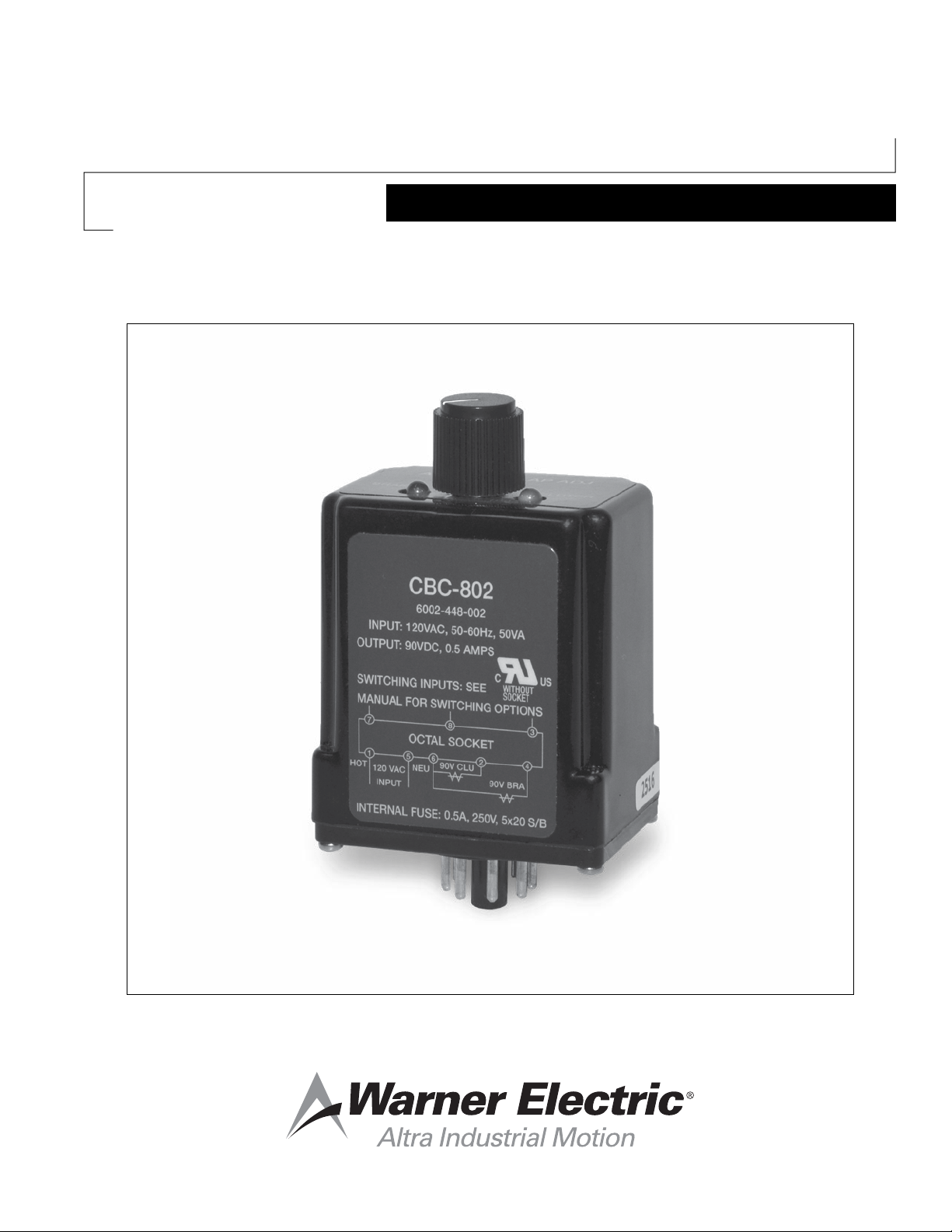
Brake (Red) and clutch
(Green) indicator lights
Potentiometer for
anti-overlap adjustment
Introduction
The CBC-802 is a solid-state clutch/brake control
designed for operation of all Warner Electric 90 volt
DC clutches and brakes with the exception of the high
torque series. It should not be used to directly power
Warner Electric permanent magnet electrically released
brakes as the units require an adjustable current or
voltage supply to provide optimum release.
The CBC-802 clutch/brake control is a direct plug-in
replacement for the previous MCS-802-2 control. The
difference between the two versions is that the CBC-802
has a potentiometer for adjustment of the anti-overlap
between clutch and brake where the MCS-802-2 was
switch selectable for preset times only. Additionally, the
fuse changed for a 3AG type for the MCS-802-2 to a
5x20mm type fuse on the CBC-802. Also included in
the CBC-802 are LED indicators indicating when the
brake or clutch is energized.
Note: This design of the CBC-802 is mounted
90degrees counter-clockwise in it’s socket,
compared to the previous design CBC-802.
The CBC-802 clutch/brake control is designed to switch
between a clutch/brake combination, two clutches or
two brakes, one unit on at a time. Control design is such
that on power up, the brake channel energizes initially,
with normal switching inputs. The time delay feature
is designed to minimize clutch/brake interaction by
reducing clutch/brake torque overlap. Indicator LED’s on
the control show when the brake channel (RED) or clutch
channel (GREEN) is energized. An internal fuse provides
protection from overload conditions. Additionally
the control is protected against output short circuit
conditions. The control does not protect from AC ground
loops or faults on the DC output side.
The control mounts in one of the two optional octal
sockets which are purchased separately. Wiring is made
at the socket terminals.
When used with the Warner Octal Sockets, the control
meets the appropriate UL and CuL certifications.
Failure to follow these instructions
may result in product damage, equipment damage,
and serious or fatal injury to personnel.
Specications
Power Input 120VAC ±10% 50/60 HZ
Output 90 VDC full wave rectified.
0.50 amps maximum.
Fusing 1/2 amp, Slo Blo, 5 x 20mm (internal)
Replacement: Buss# GDC-500mA or
Littlefuse# 0218.500MXP
Switching Momentary contact, maintained
contact, or solid state open collector
logic.
Minimum contact rating 20VDC
resistive, 0.01 amps.
Minimum input pulse – 1 millisecond.
Time Delay Adjustable potentiometer for
0to100ms - between channels
Dimensions Approx. 3-1/2’’ high x 2-1/2’’ wide x
1-3/4’’ deep.
Ambient
Temperature -20° to +122°F (-29° to +50°C)
Cycle Rate Consult the Application Engineering
section of the Warner Electric
Catalogs, P-8586-WE, P-8587-WE,
P-8588-WE, P-8589-WE, P-8590-WE
or P-1264-WE, for capabilities of your
application.
Model Part No.
CBC-802 6002-448-002
Octal Socket, Foot Mounted 6001-101-001
Din Rail Mount Octal Socket 6001-101-002

Warner Electric • 800-825-9050 P-2104-WE • 819-0548 3
To avoid injury (or even death),
always make certain all power is off before
attempting to install this control or any electrical
equipment. Do not touch the board if power is
applied.
Installation
Mounting
q1. Select a suitable location in the panel or cabinet
where the CBC-802 will be located. Insure
sufficient space is available for socket & wiring
and control when plugged into the socket.
q2. Mount the socket (foot mount) to the panel or
attach the DIN Rail Mount to its track where it
will be located. Make sure socket is properly
secured.
q3. Once socket is mounted and secured, proceed
to the control wiring section.
Dimensions
ANTI-OVERLAP ADJ
BRAKE CLUTCH
2.425” MAX
2.790"
MAX
.07" MAX
Anti-Overlap
Potentiometer
MAX
1.785"
Std. Octal Keyed Plug
Octal Socket
P/N 6001-101-001 Purchased Separately
1.57"
(39.9)
2.39"
(60.7)
.70"
(17.
8)
2.40"
(61)
.71"
(18)
1.57"
(39.9)
DIN Rail Mount Socket
P/N 6001-101-002 Purchased Separately
1.57"
(39.9)
2.39"
(60.7)
.70"
(17.
8)
2.40"
(61)
.71"
(18)
1.57"
(39.9)
Wiring Hook-up
The CBC-802 clutch/brake control is interchangeable
with its predecessor, the MCS-802-2, but is not directly
interchangeable with other Warner Electric plug-in
controls. Before actual installation of the CBC-802 into
its socket, insure all external wiring conforms to the
following hook-ups:
6
2
4
1
5
H
120 VAC,
±10%
N
CBC 802
50/60 Hz
90 V
90 V
Clutch
Brake
Power and Load Wiring
q1. Connect the hot side of the 120 VAC power to
terminal 1 of the socket and secure tightly.
q2. Connect the neutral side of the 120 VAC power
to terminal 5 of the socket and secure tightly.
Note: The “hot line” must be connected to terminal
1. This line measures 120 VAC to conduit ground.
The “neutral” line (color coded white or natural-gray)
is grounded at the 120 VAC transformer and must be
connected to terminal 5. This line measures zero VAC to
conduit ground. A chassis ground should be provided as
non-current conducting ground wire (color coded green).
q3. Connect the two (2) wires from the clutch to
terminal 2 and terminal 6 of the socket. Secure
terminal 2 tightly.
q4. Connect the two (2) wires from the brake to
terminal 4 and terminal 6 of the socket. Securely
tighten both terminals.
This is a oating type power supply
and is not referenced to AC ground. Under no
cirmcumstances should any of the output wire
leads be connected to earth or chassis ground as
the unit will be destroyed.

4Warner Electric • 800-825-9050 P-2104-WE • 819-0548
There are switching options that can be used with
the CBC-802 clutch/brake control. Determine which
switching option you will be using and wire the
switching inputs for that option.
qOption 1 – Momentary Push Button
Switches
7
8
3
START
STOP
CBC-802
Switches
Normally open
pushbutton.
Momentarily
contact closure
q 1. Connect the normally open start switch
contacts to terminals 7 and 8 of the socket.
Tighten terminal 8 securely.
q 2. Connect the normally open stop switch
contacts to terminals 7 and 3 of the socket.
Tighten both terminals securely.
q 3. This completes the wiring of the CBC-802.
Double check all terminal wiring at this time.
Proceed to the start-up section of this
manual.
qOption 2 - 2-wire Maintained Switching
7
8
3
CBC-802
7
8
3
CBC-802
or
When using option 2 for switching input, the
switch wiring must be such that in normal state the
contacts are closed at power-up to insure brake
output is energized. Switching can be either through
a maintained type switch or relay contacts as shown
above.
q 1. Connect a jumper wire from terminal 7 to
terminal 8 of the socket. Tighten terminal 8
securely.
q2. Connect the normally closed switch or
normally closed relay contacts to terminal 7
and terminal 3 of the socket. Tighten both
terminals securely.
q 3. This completes the wiring of the CBC-802.
Double check all terminal wiring at this time.
Proceed to the start-up section of this
manual.
qOption 3 - Solid State Switching – NPN
Open Collector Logic
8
3
7
CBC-802
Solid
StateSwitches
NPN type open
collector outputs,
or NPN type
transistor with
both collector
and emitter
unterminated
When using solid state
switching, the emitter or output common of
the switching device cannot be grounded. If
the outputs are grounded, then either different
switching devices must be used or an input
isolation transformer on the AC input to the
CBC-802 must be used, or the CBC-802 will be
destroyed.
q1. Connect the collector of the NPN output
transistor or switching device to terminal 3
of the socket for stop input. Tighten terminal
3 securely.
q2. Connect the collector of the NPN output
transistor or switching device to terminal 8
of the socket for start input. Tighten terminal
8 securely.
q3. Connect the emitter of the NPN output
transistors or switching device common
for both stop and start to terminal 7 of the
socket. Tighten terminal 7 securely.
q4. This completes the wiring of the CBC-802.
Double check all terminal wiring at this time.
Proceed to the start-up section of this
manual.

Warner Electric • 800-825-9050 P-2104-WE • 819-0548 5
Start-Up
The following procedure may be used to check out the
socket and wiring installation prior to plugging in and
powering the CBC-802. This procedure will check for
any grounding problem and prevent the control from
being blown. To carry out this test, a digital voltmeter
set to measure AC voltage with a range of 250 VAC is
needed.
q1. With the CBC-802 control still unplugged
from the socket, apply the 120 VAC to the
control socket.
q2. Place one test lead of the meter to terminal
1 (hot side of 120 VAC input power)
and with the other test lead of the meter
measure to the other terminals of the
socket.
qA zero volt reading should be observed between
terminal 1 and all other terminals except
terminal 5 which should measure the AC line
voltage to the socket.
qA reading of other than (0) zero volts to any of
the terminals (except 1 to 5) indicates some
type of leakage or grounding condition
and MUST be removed or the control will
potentially be destroyed on power up.
q3. Once test is complete, turn off AC power.
6543
7812
ACV
Term 1-2 0V
Term 1-3 0V
Term 1-4 0V
Term 1-5 (line
voltage 120V)
Term 1-6 0V
Term 1-7 0V
Term 1-8 0V
Note: Voltages other than zero indicates problems.
q4. After completion of ground fault checks is
done and power off to the control socket,
insert the CBC-802 into the octal socket.
Note: The socket is keyed, so control will only go in
one way.
q5. With control installed in socket, apply power
to the CBC-802. On power up, the brake
output LED (Red) should be on, and the
brake should be energized.
q6. Cycle the control between clutch/brake
channels and observe that the channel
output lights switch between brake and
clutch (Red LED to Green LED) and insure
brake and clutch are energizing properly.
q7. Start the machine and allow unit to cycle.
Make any adjustment on anti-overlap
potentiometer while machine is running.
Adjust only enough to eliminate any
interaction from one unit turning off and
other unit turning on.
Note: If time delay is set too high, a delay between
one unit turning off and other unit turning on will be
noticed. This could cause loss of control in machine
function momentarily.
q8. This completes the installation of the CBC-
802.

Warranty
Warner Electric LLC warrants that it will repair or replace (whichever it deems advisable) any product
manufactured and sold by it which proves to be defective in material or workmanship within a period of one (1)
year from the date of original purchase for consumer, commercial or industrial use.
This warranty extends only to the original purchaser and is not transferable or assignable without Warner Electric
LLC’s prior consent.
Warranty service can be obtained in the U.S.A. by returning any defective product, transportation charges
prepaid, to the appropriate Warner Electric LLC factory. Additional warranty information may be obtained by
writing the Customer Satisfaction Department, Warner Electric LLC, 449 Gardner Street, South Beloit, Illinois
61080, or by calling 815-389-3771.
A purchase receipt or other proof of original purchase will be required before warranty service is rendered. If
found defective under the terms of this warranty, repair or replacement will be made, without charge, together
with a refund for transportation costs. If found not to be defective, you will be notified and, with your consent, the
item will be repaired or replaced and returned to you at your expense.
This warranty covers normal use and does not cover damage or defect which results from alteration, accident,
neglect, or improper installation, operation, or maintenance.
Some states do not allow limitation on how long an implied warranty lasts, so the above limitation may not apply
to you.
Warner Electric LLC’s obligation under this warranty is limited to the repair or replacement of the defective
product and in no event shall Warner Electric LLC be liable for consequential, indirect, or incidental damages of
any kind incurred by reason of the manufacture, sale or use of any defective product. Warner Electric LLC neither
assumes nor authorizes any other person to give any other warranty or to assume any other obligation or liability
on its behalf.
WITH RESPECT TO CONSUMER USE OF THE PRODUCT, ANY IMPLIED WARRANTIES WHICH THE
CONSUMER MAY HAVE ARE LIMITED IN DURATION TO ONE YEAR FROM THE DATE OF ORIGINAL
CONSUMER PURCHASE. WITH RESPECT TO COMMERCIAL AND INDUSTRIAL USES OF THE PRODUCT,
THE FOREGOING WARRANTY IS IN LIEU OF AND EXCLUDES ALL OTHER WARRANTIES, WHETHER
EXPRESSED OR IMPLIED BY OPERATION OF LAW OR OTHERWISE, INCLUDING, BUT NOT LIMITED TO,
ANY IMPLIED WARRANTIES OF MERCHANTABILITY OR FITNESS.
Some states do not allow the exclusion or limitation of incidental or consequential damages, so the above
limitation or exclusion may not apply to you. This warranty gives you specific legal rights and you may also have
other rights which vary from state to state.
Changes in Dimensions and Specications
All dimensions and specifications shown in Warner Electric catalogs are subject to change without notice.
Weights do not include weight of boxing for shipment. Certified prints will be furnished without charge on request
to Warner Electric.
P-2104-WE 819-0548 1/19
www.warnerelectric.com
31 Industrial Park Road
New Hartford, CT 06057
815-389-3771
Other Warner Electric Controllers manuals
Popular Controllers manuals by other brands

Smartgen
Smartgen HEM8500 user manual

National Instruments
National Instruments PXI-8106 user manual

Ruijie
Ruijie RG-WS6108 Series Hardware installation and reference guide

Lincoln
Lincoln LMC 1 user manual

Measurement Computing
Measurement Computing MP-2000 quick start guide

Heat Outdoors
Heat Outdoors QHC18MR Quick start guide & instructions