Secure Home SH-5525 User manual

© 2012 HeathCo LLC 598-1161-04
1 Halogen
Lamp
Sensor
Light Control
Requirements
• Thelightcontrolrequires120-voltsAC.
• IfyouwanttouseManualMode,thecontrolmustbe
wiredthroughaswitch.
• Some codes require installation by a qualied
electrician.
• Thisproductisintendedforusewiththeenclosed
gasketandwithajunctionboxmarkedforuseinwet
locations.
ModelSH-5525
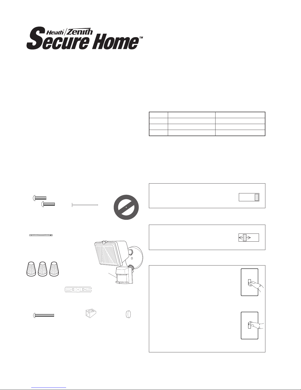
3 Wire
Connectors
6Screws
(3sizesincluded) Gasket
MountingBolt
MountingStrap
LightShield
PlasticHanger
RubberPlug
Thispackageincludes:
OPERATION
*resetstoAutoModeatdawn.
TEST
10 5 1 TEST
ON-TIME
Put the ON-TIME switch on the
bottomofthesensorintheTEST
position.
MANUALMODE
ON-TIME
1051TEST
...backon.
AUTO
1SecondOFF
then...
Note:Whenrstturnedonwaitabout11/2minutesfor
thecircuitrytocalibrate.
Manual mode only works at night
becausedaylightreturnsthesensor
toAUTO.
Flipthelightswitchoffforonesecond
thenbackontotogglebetweenAUTO
andMANUALMODE.
Manual mode works only with the
ON-TIMEswitchinthe1, 5,or10
position.
PuttheON-TIMEswitchinthe
1,5,or10minuteposition.
Mode: On-Time: Works: Day Night
Test 5Sec x x
Normal 1,5,10min. x
Manual UntilDawn* x
Features
• Turnsonlightingwhenmotionisdetected.
• Automaticallyturnslightingoff.
• BulbSaver™-Extendsbulblifebyupto4xstandard
bulbs.Lightsbulbtofullbrightinunder2seconds.
• Photocellkeepsthelightingoffduringdaylighthours.
• LEDindicatesmotionwassensed(dayornight).
MotionSensing
HalogenFixture
2598-1161-04
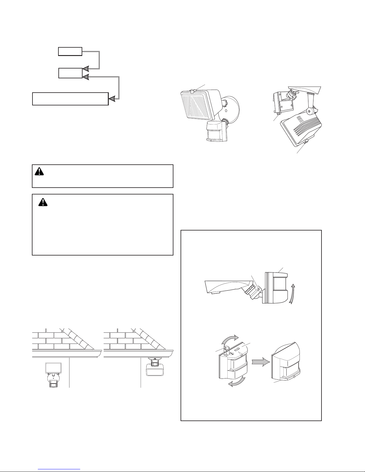
Foreavemountonly:
1. Swingthesensorheadtowardstheclampscrew
joint.
If the sensor pops out of the ball joint, loosen the
clampscrewandpushthesensorbackintotheball
joint.Tightentheclampscrewwhendone.
2. Thenrotatethesensorheadclockwise180°so
thecontrolsfacedown.
Controls
Controls
Controls
ClampScrew
LensRetainer
LightShield,
withopening
atthisside
• Notethepositionofthevariouspartsofthexturefor
thetypeofinstallationforyourapplicationandadjust
thelampheadandsensorasshownbelow.
LensRetainer
LightShield
Opening
Move ON-TIME Switch
to 1, 5, or 10 minutes
ModeSwitchingSummary
Flip light switch
off for one second
then back on*
MANUAL MODE
AUTO
TEST
* Ifyougetconfusedwhileswitchingmodes,turnthe
poweroffforoneminute,thenbackon.Afterthecali-
brationtimethecontrolwillbeintheAUTOmode.
INSTALLATION
Foreasyinstallation,selectanexistinglightoperated
byawallswitchforreplacement.IMPORTANT:DoNOT
usewithdimmersortimers.
Forbestperformance,mountthextureabout8feet
(2.4m)abovetheground.NOTE:Ifxtureismounted
higherthan8feet(2.4m),aimingthesensordownwill
reducecoveragedistance.
CAUTION:ToAvoidFireOrBurnHazards:
•Allowxturetocoolbeforetouching.Thebulband
thextureoperateathightemperatures.
•
Keepxtureatleast2"(51mm)fromcombustiblema-
terials.Donotaimatobjectscloserthan3feet(1m).
•UseonlyT3,250W(maximum)tungstenhalogen
120VAClamps.
NOTE: Lightxtureandsensorshouldbemountedas
shownabovewheninstalled(dependingupontypeof
installation).
CAUTION:Keepthesensoratleast1"(25mm)
awayfromthebulbs.
WallMount EaveMount
WallMount EaveMount
Beforeinstallingthelightxtureunderaneave,the
sensorheadmustberotatedasshowninthenext
twostepsforproperoperationandtoavoidtheriskof
electricalshock.
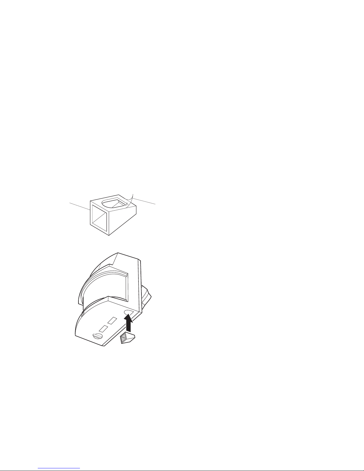
IMPORTANT: Forproperunder-eaveoperation,install
lightshield(included).SeeLight Shield Installation
fordetails.

3
598-1161-04
1. Removetheexistinglightxture.
2. Installmountingstraptojunctionboxusingscrews
appropriateforyourjunctionbox.
3. Theplastichangercanbeusedtoholdthexture
whilewiring.Thesmallendoftheplastichanger
canbethreadedthroughtheholeinthecenterof
thecoverplate.Thesmallendthengoesintoone
oftheslotsonthemountingstrap.
4. Threadallxturewiresthroughthelargeholesin
thegasketasshown.
5. Connectthejunctionboxwirestothelightxture
wiresasshown.Twisttogetherandsecurewithwire
connectors.
White to White Black to Black
Connectanyxturegroundwire(s)andthecoverplate
groundscrewtothejunctionboxgroundwire.
Gasket
MountingStrap
Mounting
Bolt
MounttheLightControl
1. Alignthelightcontrolcoverplateandcoverplate
gasket.Securewiththemountingbolt.
2. Pushtherubberplugrmlyintoplace.
3. Ifawetlocationjunctionboxwasnotused,caulk
thewallplatemountingsurfacewithsiliconeweather
sealant.
Rubber
Plug
WARNING:Turn power off at circuitbreaker
orfuse.
WiretheLightControl
NOTE:Thebulbisincluded,butneedstobeinstalled.
Thebulbislocatedbehindtheglasscoverofthe
lamphead.
1. Removeglasscoverandremovetheoldbulbby
pushingthebulbtowardstherightuntiltheleftside
ofthebulbisclearoftheleftsocket.
2. Toinstallthebulb,placeoneendofthebulbonthe
contactintherightsocket.Whilepushingthebulb
againsttherightcontact,lowertheotherendofthe
bulbontothecontactintheleftsocket.
3. Spinthebulbtoverifyitisseatedproperly.
4. Re-installtheglasscover.
Forproperoperationandsafety,thelightxturemust
beabovethesensorandthesensorheadmustbe
rotatedsothatthecontrolsareonthebottom.
1
2
Left
Socket Right
Socket
Contact
Bulb LampHead
CAUTION:Whenreplacingthebulb,turnpower
offandletthexturecool.
Important:Useacleangloveorclothwhenhandling
thenewbulb.Useisopropyl(rubbing)alcoholtoclean
thebulbifitistouchedwithyourbarehands.
BulbInstallationandReplacement

4598-1161-04
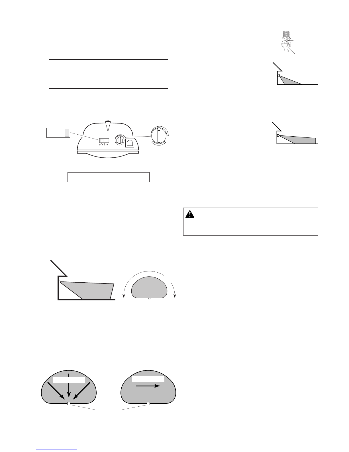
TESTANDADJUSTMENT
1. Turnonthecircuitbreakerandlightswitch.
NOTE: Sensorhasabout11/2minuteswarmupperiod
beforeitwilldetectmotion.Whenrstturned
on,waitabout11/2minutes.
2. TurntheRANGEcontroltotheminimumposition
(MIN)andtheON-TIMEcontroltotheTESTposi-
tion.
Avoidaimingthecontrolat:
•Objects that change temperature rapidly, such as
heating vents and air conditioners.These heat
sourcescouldcausefalsetriggering.
•Areaswherepetsortrafcmaytriggerthecontrol.
•Nearbylarge,light-coloredobjectsreectinglight
maytriggertheshut-offfeature.Donotpointother
lightsatthesensor.
BottomofSensor
Maximum Range Maximum
Coverage Angle
70ft.
(21m)
8ft.
(2.4m)
Least Sensitive Most Sensitive
NOTE:
Ifxtureismountedhigherthan8ft.(2.4m),aiming
thesensordownwillreducecoveragedistance.
Thedetectorismostsensitivetomotionacrossitseld
ofview.
1. Loosentheclampscrewinthe
sensorballjointandgently
rotatethesensor.
2. Walk through the coverage
area noting where you are
whenthelightsturnon(also,
theLEDwillashseveraltimes
whenmotionisdetected).Move
thesensorheadup,down,or
sidewaystochangethecover-
agearea.Keepthesensorat
least1"(2.5cm)awayfrom
thelamp.
3. AdjusttheRANGEasneeded.
RANGE set too high may
increasefalsetriggering.
4. Secure the sensor head
by tightening the clamp
screw. Do not overtighten
thescrew.
5. SettheamountofTIMEyouwantthelightstostay
onaftermotionisdetected(1,5,or10minutes).
180°
Motion
Motion
Sensor
Clamp
Screw
Ball
Joint
AimSensor
DownforShort
Coverage
AimSensor
HigherforLong
Coverage
RANGE
1051TEST
ON-TIME
MAXMIN
RANGEON-TIME
10 5 1 TEST
MINUTES
MIN MAX
LightShieldInstallation
Ifyourlightdoesnotcomeonatduskorturnsoffun-
expectedly,thenanotherlightsourcemaybeactivating
thedaytimeshutofffeature.Possiblesourcesoflight
interferencearestreetlights,landscapelighting,other
securitylightsorlanterns,oraninteriorhouselightshin-
ingthroughawindow.Itcouldalsobereectivelight,
suchasfromapoolorlightcoloredwall.
Toinstallthelightshield,followthesesimplesteps.
1. Removeprotectivebackingfromthebottomofthe
lightshield.
2. Position light shield over the photocell with the
openingfacingawayfromtheinterferinglight.
3. Presstheadhesivesidermlyagainstthephotocell
tomountitpermanentlyinplace.
WARNING-Riskofre.Donotaimthebulbs
atacombustiblesurfacewithin3ft.(1m).

5
598-1161-04
SPECIFICATIONS
Range............. Upto70ft.(21m)[varieswith
surroundingtemperature].
SensingAngle....... Upto180°
ElectricalLoad....... Up to 250 Watts Maximum
Tungsten.
PowerRequirements.. 120VAC,60Hz
OperatingModes..... TEST, AUTO and MANUAL
MODE
TimeDelay ......... 1,5,10minutes
Replacementlamp.... T3, 250W (or less) halogen
120VAC
HeathCoLLCreservestherighttodiscontinueproducts
andtochangespecicationsatanytimewithoutincurring
anyobligationtoincorporatenewfeaturesinproducts
previouslysold.
TROUBLESHOOTINGGUIDE
SYMPTOM POSSIBLECAUSE SOLUTION
Lightwillnotcomeon. 1. Lightswitchisturnedoff.
2. Lampislooseorburnedout.
3. Fuseisblownorcircuitbreakeristurnedoff.
4. Daylightturn-offisineffect.
5. Incorrectcircuitwiring,ifthisisanewinstallation.
6. Lightcontrolaimedinwrongdirection.
1. Turnlightswitchon.
2. Checklampandreplaceifburnedout.
3. Replacefuseorturncircuitbreakeron.
4. Recheckafterdark.
5. Verifywiringiscorrect.
6. Re-aimlightcontroltocoverdesiredarea.
Lightcomesoninday-
light.
1. Light control may be installed in a relatively dark
location.
2. LightcontrolisinTEST.
1. Thextureisoperatingnormallyunderthesecondi-
tions.
2. Setcontrolswitchto1,5,or10minutes.
Light comes on for no
apparentreason.
1. Lightcontrolmaybesensingsmallanimalsorauto-
mobiletrafc.
2. Rangeissettoohigh.
1. Re-aimlightcontrol.
2. Reducerange.
Lightstaysoncontinu-
ously.
1. Alampispositionedtooclosetothelightcontrolor
pointedatnearbyobjectsthatcauseheattotrigger
thelightcontrol.
2. Thelightcontrolmaybepickingupaheatsource
likeanairvent,dryervent,orbrightlypainted,heat-
reectivesurface.
3. Lightcontrolisinmanualmode.
1. Repositionthelampawayfromthelightcontrolor
nearbyobjects.
2. Re-aimlightcontrol.Reducerange.
3. SwitchlightcontroltoAUTO.
Light flashes on and
off.
1. Heatorlightfromthelampsmaybeturningthelight
controlonandoff.
2. Heatbeingreectedfromotherobjectsmaybeturn-
ingthelightcontrolonandoff.
3. LightcontrolisintheTESTmodeandwarmingup.
4. Ifeaveinstallation,lightshieldnotinstalledproperly.
1. Repositionthelampawayfromthelightcontrol.
2. Repositionlightcontrol.
3. Flashingisnormalundertheseconditions.
4. Installlightshieldaccordingtoinstructions.
Lightashesonce,then
stays off in manual
mode.
Lightcontrolisdetectingitsownlights. Repositionlamptokeepareabelowthe lightcontrol
relativelydark.
Protective
Backing
Light
Shield

6598-1161-04
TWOYEARLIMITEDWARRANTY
Thisisa“LimitedWarranty”whichgivesyouspeciclegalrights.Youmayalsohaveotherrightswhichvaryfrom
statetostateorprovincetoprovince.
Foraperiodoftwoyearsfromthedateofpurchase,anymalfunctioncausedbyfactorydefectivepartsor
workmanshipwillbecorrectedatnochargetoyou.
NotCovered-Repairservice,adjustmentandcalibrationduetomisuse,abuseornegligence,lightbulbs,
batteries,andotherexpendableitemsarenotcoveredbythiswarranty.Unauthorizedserviceormodica-
tionoftheproductorofanyfurnishedcomponentwillvoidthiswarrantyinitsentirety.Thiswarrantydoes
notincludereimbursementforinconvenience,installation,setuptime,lossofuse,unauthorizedservice,or
returnshippingcharges.
ThiswarrantycoversonlyHeathCoLLCassembledproductsandisnotextendedtootherequipmentand
componentsthatacustomerusesinconjunctionwithourproducts.
THIS WARRANTY IS EXPRESSLY IN LIEU OF ALL OTHER WARRANTIES, EXPRESS OR IMPLIED,
INCLUDINGANYWARRANTY,REPRESENTATIONORCONDITIONOFMERCHANTABILITYORTHAT
THEPRODUCTSAREFITFORANYPARTICULARPURPOSEORUSE,ANDSPECIFICALLYINLIEUOF
ALLSPECIAL,INDIRECT,INCIDENTAL,ORCONSEQUENTIALDAMAGES.
REPAIRORREPLACEMENTSHALLBETHESOLEREMEDYOFTHECUSTOMERANDTHERESHALL
BENOLIABILITYONTHEPARTOFHEATHCOLLCFORANYSPECIAL,INDIRECT,INCIDENTAL,OR
CONSEQUENTIALDAMAGES,INCLUDINGBUTNOTLIMITEDTOANYLOSSOFBUSINESSORPROF-
ITS,WHETHERORNOTFORESEEABLE.Somestatesorprovincesdonotallowtheexclusionorlimitation
ofincidentalorconsequentialdamages,sotheabovelimitationorexclusionmaynotapplytoyou.Please
keepyourdatedsalesreceipt,itisrequiredforallwarrantyrequests.
TECHNICALSERVICE
Pleasecall1-800-858-8501(Englishspeakingonly)forassistancebeforereturning
producttostore.
Ifyouexperienceaproblem,followthisguide.YoumayalsowanttovisitourWebsiteat:www.hzsupport.com.
Iftheproblempersists,call*forassistanceat1-800-858-8501(Englishspeakingonly),8:00AMto5:00PMCST
(M-F).Youmayalsowrite*to:
HeathCo LLC
P.O.Box90045
BowlingGreen,KY42102-9045
ATTN:TechnicalService
*IfcontactingTechnicalService,pleasehavethefollowinginformationavailable:ModelNumber,DateofPur-
chase,andPlaceofPurchase.
NoServicePartsAvailableforthisProduct
Pleasekeepyourdatedsalesreceipt,itisrequiredforallwarrantyrequests.

7
598-1161-04
1Bombilla
Halógena
Detector
Controldeluz
Requisitos
• Elcontroldeluzrequiere120VCA.
• ParausarelModoManual,conecteelcontrolconun
interruptor.
• Algunos códigos requieren instalación por un
electricistacalicado.
• Serecomiendausaresteproductoconelempaque
provistoyconunacajadeempalmemarcadapara
usoenlugareshúmedos.
AparatodeHalógenoy
DetectordeMovimiento
ModeloSH-5525
3conectores
dealambre
6tornillos
(3dimensiones)
Empaquetadura
Protectorde
lámpara
1 perno
Láminademontaje
Colgadorplástico
Enchufede
caucho
Estepaquetetiene:
©2012HeathCoLLC 598-1161-04S
Características
• Prendelaluzcuandodetectamovimiento.
• Apagalaluzautomáticamente.
• BulbSaver™-Prolongalavidadelabombillahasta
4vecesconrespectoalasbombillasestándar.Las
bombillasalcanzanlabrillanteztotalenmenosde2
segundos.
•
Lafotocélulamantienelaluzapagadaduranteeldía.
• LEDindicaquesehadetectadomovimiento(durante
eldíaolanoche).
FUNCIONAMIENTO
*SeponeenAutomáticoalamanecer.
ParaMODOMANUAL:
...préndalo.
1segundo
APAGADO
luego...
ParaAUTOMATICO:
ParaPRUEBA:
Nota:Cuandoloprendaporprimeravezespere11/2
minutoshastaqueelcircuitosecalibre.
Pongaelcontroldetiempo(ON-TIME)
enlaposiciónde1,5o10minutos.
Elmodomanualfuncionasóloporla
nocheporquelaluzdeldíaponeal
detectorenmodoAUTOMATICO.
Apagueelinterruptorporunsegundo
yvuélvaloaprender.
Elmodomanualfuncionasólocuando
elinterruptordetiempo(ON-TIME)está
enlaposiciónde1,5o10minutos.
Fase: Tiempodeencendido: Trabaja: día noche
Prueba 5segundos x x
Autom. 1,5,10minutos x
Manual Hastaelamanecer* x
Pongaelinterruptordetiempo(ON-
TIME), al fondo del detector, en la
posicióndeprueba(TEST).
10 5 1 TEST
ON-TIME
ON-TIME
1051TEST

8598-1161-04
Mueva el interruptor de tiempo
(ON-TIME) a 1, 5 o 10 minutos
Apague el interruptor por
un segundo y préndalo de
nuevo
Resumendelasmodalidadesdel
interruptor
* Siseconfundemientrascambiadefases,apague
laelectricidadporunminutoypréndaladenuevo.
Despuésdeltiempodecalibraciónelcontrolestará
enfaseAUTO(MATICA).
PRUEBA
AUTOM.
MODO
MANUAL
Montajeenpared Montajeenalero
Protectorde
lámparacon
aperturaen
estelado
• Notelaposicióndelasvariaspartesdelaparatopara
eltipodeinstalaciónquenecesitasuaplicacióny
ajusteelcabezaldelalámparayeldetectorcomo
semuestraabajo.
Retenedordela
placatranslúcida
1. Gire la cabeza del detector hacia la unión del
tornillosujetador.
Sóloparamontajeeléctrico:
Controles
TornilloSujetador
2. Entonces gire la cabeza del detector hacia la
derechapor180°hastaqueloscontrolesmiren
haciaabajo.
Sieldetectorsesaledelauniónesférica,aojeel
tornillosujetadoryempujeeldetectorhaciadentro
de la unión esférica. Apriete el tornillo sujetador
cuandotermine.
Controles
Controles
Aperturadel
protectorde
lámpara
Retenedordelaplacatranslúcida
Para una fácil instalación escoja una luz con un
interruptor de pared. IMPORTANTE: No lo use con
temporizadoresoatenuadoresdeluz.
Paraunmejorfuncionamiento,instaleelaparatoacasi
2.4mdelsuelo.
NOTA:Sielaparatoestáinstaladoa
másde8pies(2,4m),siseapuntaeldetectorhacia
abajosereduciráladistanciadecobertura.
INSTALACIÓN
Antesdeinstalarlalámparabajounalero,lacabeza
delsensordeberotarsecomosemuestraenlosdos
pasossiguientesparalacorrectaoperaciónyevitarel
riesgodedescargaeléctrica.
IMPORTANTE: Para un funcionamiento correcto
debajodelalero,instaleelprotectordelaluz(in-
cluido).VeaInstalación del Protector de la luzpara
másdetalles.
Montajeenpared Montajeenalero
NOTA:Lalámparayelsensordebemontarsecomo
seindicaarriba,unavezinstalado(segúneltipode
instalación).
CUIDADO:Paraevitarlospeligrosdeincen-
diooquemazón:
• Dejequeelelementoseenfríeantesdetocarlo.Labom-
billayelelementofuncionanaaltastemperaturas.
• Mantengaalelementoporlomenosa51mmde
losmateriales combustibles. No lo apunte hacia
objetosqueesténmáscercade1m.
• UsesólolámparashalógenasdetungstenodeT3,
120VCAyde250vatiosmáximo.
CUIDADO:Mantengaaldetectorporlomenos
a25mmdelaslámparas.

9
598-1161-04
1. Quiteelaparatodeluzexistente.
2. Instalelaláminademontajealacajadeempal-
meusandotornillosapropiadosparalacajade
empalme.
3. Sepuedeusarelcolgadorplásticoparasostener
elaparatomientrasseinstalaelcableado.Elex-
tremopequeñodelcolgadorsepuedepasarpor
elagujeroenelcentrodelaplacacubertora.El
extremopequeñovaluegodentrodelasranuras
delaláminademontaje.
4. Pasetodosloscablesdelaparatoporlosagujeros
grandesdelempaque,comosemuestra.
5. Conecte los cables de la caja de empalme con
loscablesdelaparatodeluz,comosemuestra.
Tuérazalosjuntos yasegúreloscon un conector
decables.
Blanco a Blanco
Negro a Negro
láminade
montaje
Pernode
montaje
Conecte los alambres del aparato, propuestos
paraconexiónatierra,alaconexiónatierrade
lacajadeenpalme.
InstaleelControldeLuz
1. Pongaelpernodemontajeatravésdelfrentede
latapadelacajadeempalme.Empujeelagujero
pequeñodelaempaquetadurasobreeltornillode
montaje.
2. Empujeeltapóndecauchormementehastaque
encaje.
3. Si noseusó unacajadeempalmeen unlugar
húmedo,calafateelasuperciedemontajedela
placadelaparedconunselladordesiliconacontra
laintemperie.
Enchufede
Caucho
Empaquetadura
ADVERTENCIA:Desconectelaenergíaenel
disyuntor.
ConecteelControldeLuzInstalaciónyCambiodeBombilla
NOTA: La bombilla se incluyen pero deben ser
instaladas.Labombillaseencuentrandetrásdela
coberturadevidriodecadacabezaldelámpara.
1. Quitelacubiertadevidrioyquitelabombillavieja
empujándolahacialaderechahastaqueellado
izquierdodelabombillasesalgadelenchufeiz-
quierdo.
2. Parainstalarlabombilla,pongaunextremodela
bombillasobre el contacto delenchufe derecho.
Mientras empuja la bombilla contra el contacto
derecho,bajeelotroextremodelabombillasobre
elcontactodelenchufeizquierdo.
3. Girelabombillaparavericarqueestécorrecta-
menteasentada.
4. Coloquelacubiertadevidrio.
Para un funcionamiento apropiado y seguro, el
aparato de luz (lámpara) debe estar encima del
sensoryalacabezadelsensorseladebegirar
de modo que los controles queden en la parte
inferior.
1
2
Enchufe
izquierdo Enchufe
derecho
Contacto
Bombilla Cabezalde
la lámpara
CUIDADO:Cuandocambielabombilla,apague
laenergíaydejequeelaparatoseenfríe.
Importante:Cuandomanipulelabombillanuevause
unguanteounpañoqueesténlimpios.Usealcohol
isopropílico(frotando)paralimpiarlabombillasiha
sidotocadaconmanosdesprotegidas.

10 598-1161-04
PRUEBAYAJUSTE
1. Prendaelcortacircuitosyelinterruptordeluz.
NOTA: Eldetectortieneunperíododecercade11/2
minutosdecalentamientoantesdedetectar
movimiento. Cuando lo prenda por primera
vez,espere11/2minutos.
2. GireelcontrolRANGEalaposiciónmínima(MIN)
yelcontrolON-TIMEalaposiciónTEST.
3. Aojeeltornillosujetadorenla
uniónesféricaygiredespacio
eldetector.
4. Camine por el área a prote-
gerse y dése cuenta dónde
estácuandoseprendelaluz
(además, el LED destellará
variasvecescuandosedetecta
movimiento).Muevalacabeza
deldetectorhaciaarriba,hacia
abajo o hacia los lados para
cambiareláreadeprotección.
Mantenga al detector por
lo menos a 1 pulgada (2.5
cm)delaslámparas.
5. Fije la sensibilidad (RANGE)
como necesite. Demasiada
sensibilidad puede aumentar
lasfalsasalarmas.
6. Asegurelapunteríadelaca-
bezadeldetectorajustandoeltornillosujetador.
Noloaprietedemasiado.
7. Fijeelperíododetiempo(ON-TIME)quelaluzdebe
quedarseprendidadespuésdedetectarmovimiento
(1,5o10minutos).
Partedeabajodeldetector
Eviteapuntarelcontrolhacia:
•Objetosquecambienrápidamentedetemperatura
talescomoductosdecalefacciónyacondiciona-
doresdeaire.Estasfuentesdecalorpuedencausar
falsasalarmas.
•Áreas donde animales domésticos o el tráco
puedanactivarelcontrol.
•Losobjetosgrandescercanosydecoloresres-
plandecientes que reejan la luz del día pueden
hacerqueeldetectorseapague.Noapunteotras
luceshaciaeldetector.
70pies
(21m)
8pies
(2.4m)
Lo menos sensible Lo más sensible
Detector
Movimiento
Movimiento
ADVERTENCIA:Riesgodeincendio.Noapunte
laslámparasasuperciescombustiblesdentro
deun3pies(1m).
Alcance Máximo Angulo de
Cobertura Máxima
RANGE
1051TEST
ON-TIME
MAXMIN
RANGEON-TIME
10 5 1 TEST
MINUTES
MIN MAX
Tornillo
Sujetador
Unión
Esférica
Apunteel
detectorhacia
abajoparapoca
cobertura
Apunteel
detectormás
arribapara
mayorcobertura
180°
NOTA:Sielaparatoestáinstaladoamásde8pies(2,4
m),siseapuntaeldetectorhaciaabajosereducirála
distanciadecobertura.
Eldetectoresmenossensibledelmovimientoquese
dirigehaciaél.
11
598-1161-04
ESPECIFICACIONES
Alcance............. Hasta 21 m (varía con la
temperatura del medio am-
biente).
Angulodedetección...Hasta180°
CargaEléctrica.......Hasta250VatiosMáximode
luzincandescentehalógeno
Requisitosdeenergía..120VCA,60Hz
FasesdeOperación ...PRUEBA, AUTOMATICO, y
MODOMANUAL
RetardodeTiempo....Ajustablede1,5,o10minu-
tos
Bombilladerepuesto...T halógena de dos clavijas
de120VCAyde250W
HeathCoLLCsereservaelderechodedescontinuar
productosydecambiarespecicacionesacualquier
momentosinincurrirenningunaobligacióndetener
queincorporarnuevascaracterísticasenlosproductos
vendidosconanterioridad.
InstalacióndelProtectordeLuz
Silaluznoseprendealanocheceroseapaga
inesperadamente,otrafuentedeluzpuedeestar
activandoelelementodeapaguedeldía.Lasposi-
blesfuentesdeinterferenciadeluzsonlaslucesde
lacalle,elalumbradodelosjardines,otraslucesde
seguridadofaroles,olaluzinteriordeunacasaque
brillaatravésdeunaventana.Puedetambiénser
unaluzreectante,comoeldeunapiscinaopared
decolorbrillante.
Parainstalarelprotectordelaluz,sigaestospasos
sencillos.
1. Quiteelprotectoradhesivodelaparteinferiordel
protectordelaluz.
2. Pongaelprotectordelaluzsobrelafotocélulacon
suaberturahaciaelotroladodelaluzdeinterfe-
rencia.
3. Presionermementeelladoconlacintaadhesiva
contralafotocélulaparamontarlapermanentemente
ensusitio.
Protector
adhesivo
Protector
delaluz

12 598-1161-04
GUIADEINVESTIGACIONDEAVERIAS
SÍNTOMA POSIBLECAUSA SOLUCIÓN
Laluznoseenciende. 1. Elinterruptordeluzestáapagado.
2. Elfaroestáojooquemado.
3. El fusible está quemado o el cortacircuitos está
apagado.
4. Ladesconexióndeluzdeldíaestáenefecto.
5. Alambradoincorrecto,siéstaesunanuevainstala-
ción.
6. Elcontroldeluzestáapuntandoendireccióninco-
rrecta.
1. Enciendaelinterruptordeluz.
2. Reviseelfaroycambiesiestáquemado.
3. Cambieelfusibleenciendaeldisyuntor.
4. Compruébelocuandocomiencelaobscuridad.
5. Veriquequeelcableadoestécorrecto.
6. Vuelvaaapuntarelcontroldeluzparaquecubrael
áreadeseada.
Laluzseprendedurante
eldía.
1. Elcontroldeluzpuedeestarinstaladoenunlugar
relativamenteoscuro.
2. ElcontroldeluzestáenfasedePrueba.
1. Elaparatoestáfuncionandonormalmentebajoestas
condiciones.
2. Fijeelinterruptordecontrola1,5o10minutos.
La luz se prende sin
ninguna razón apa-
rente.
1. Elcontroldeluzpuedeestardetectandoanimales
pequeñosoeltrásitodeautomóviles.
2. Elmargenestápuestomuyalto.
1. Reapunteelcontroldeluz.
2. ApagueelAumentodeDistancia.
Laluzsequedaprendida
continuamente.
1. Elfaroestámuycercadelcontroldeluzoapuntando
aobjetoscercanosquegenerancaloryactivanel
controldeluz.
2. Elcontroldeluzestáapuntandohaciaunafuentedecalor
talcomounconductodeaire,desecadoraohaciauna
supercieconpinturabrillanteyquereejaelcalor.
3. Elcontroldeluzestáenelmodomanual.
1. Reubiqueelfarolejosdelcontroldeluzodeobjetos
cercanos.
2. Reapunteelcontroldeluz.ApagueelAumentode
Distancia.
3. CambieelcontroldeluzaAUTO.
La luz se prende y se
apaga.
1. Elcalorolaluzdelosfarospuedeestarencendiendo
yapagandoelcontroldeluz.
2. El calor reejado por otros objetos puede estar
encendiendoyapagandoelcontroldeluz.
3. ElcontroldeluzestáenfasedePruebaycalentán-
dose.
4. Siesunaconexióndealero,elprotectordelámpara
noestáinstaladocorrectamente.
1. Reubiqueelfarolejosdelcontroldeluz.
2. Reubiqueelcontroldeluz.
3. Elprenderseyapagarseesnormalbajoestascon-
diciones.
4. Instale el protector de lámpara de acuerdo a las
instrucciones.
La luz se prende una
vezyluegopermanece
apagada en la fase
Manual.
Elcontroldeluzestádetectandosupropialuz. Reubiquelosfarosparamantenerrelativamenteobscura
lazonadebajodelalámpara.

13
598-1161-04
GARANTÍALIMITADAA2AÑOS
Estaesuna“GarantíaLimitada”queledaaUd.derechoslegalesespecícos.Ustedpuedetambiéntener
otrosderechosquevaríandeestadoaestadoodeprovinciaaprovincia.
Porunperíodode2añosdesdelafechadecompra,cualquiermalfuncionamientoocasionadoporpartes
defectuosasdefábricaomanodeobraserácorregidosincargoparaUd.
Nocubierto-Serviciodereparación,ajusteycalibracióndebidoalmaluso,abusoonegligencia,bombi-
llas,baterías,uotraspartesfungiblesnoestáncubiertasporestagarantía.LosServiciosnoautorizados
omodicacionesdelproductoodecualquiercomponentequeseproveeinvalidaránestagarantíaensu
totalidad.Estagarantíanoincluyereembolsoporinconveniencia,instalación,tiempodeinstalación,perdida
deuso,servicionoautorizado,ocostosdetransportederetorno.
EstagarantíacubresolamentelosproductosensambladosporHeathCoLLCynoseextiendeaotrosequi-
posocomponentesqueelconsumidorusajuntoconnuestrosproductos.
ESTAGARANTÍAESTÁEXPRESAMENTEENLUGARDEOTRASGARANTÍAS,EXPRESADASOSO-
BREENTENDIDAS, INCLUYENDO CUALQUIER GARANTÍA, REPRESENTACIÓN O CONDICIÓN DE
COMERCIABILIDADOQUELOSPRODUCTOSSEADAPTENPARACUALQUIERPROPÓSITOOUSO
ENPARTICULAR,YESPECIFICAMENTEENLUGARDETODOSLOSDAÑOSESPECIALES,INDIREC-
TOS,INCIDENTALESYCONSECUENTES.
LAREPARACIÓNOELREEMPLAZODEBERÍASERLAÚNICASOLUCIÓNDELCLIENTEYNOHABRÁ
RESPONSABILIDADPORPARTEDEHEATHCOLLCPORCUALQUIERDAÑOESPECIAL,INDIRECTO,
INCIDENTALOCONSECUENTE,INCLUIDOSPERONOLIMITADOSACUALQUIERPÉRDIDADENE-
GOCIOOGANACIASSEANONOPREVISIBLES.Algunosestadosoprovinciasnopermitenlaexclusión
olimitacióndedañosincidentalesoconsecuentes,demodoquelalimitaciónoexclusiónarribaindicada
puedequenoseapliqueaUd.Porfavorguardesurecibodeventafechado;selorequiereparacual-
quiersolicituddegarantía.
SERVICIOTÉCNICO
Favordellamaral1-800-858-8501(sóloparahablareninglés)parapedirayudaantes
dedevolverelproductoalatienda.
Sitienealgúnproblema,sigaestaguía.UstedpuedetambiénvisitarnuestrositioWeb:www.hzsupport.com.
Sielproblemacontinúa,llameal1-800-858-8501(sóloparahablareninglés),de8:00AMa5:00PMCST(L-
V).Ustedpuedetambiénescribira:
HeathCo LLC
P.O.Box90045
BowlingGreen,KY42102-9045
ATTN:TechnicalService(ServicioTécnico)
*SisellamaalServicioTécnico,porfavortenerlistalasiguienteinformación:NúmerodeModelo,Fechade
comprayLugardecompra.
Nohaypiezasdeserviciodisponiblesparaesteproducto.
Porfavorguardesurecibodeventafechado;selorequiereparacualquiersolicituddegarantía.
14 598-1161-04
ModèleSH-5525
Luminaire-détecteurde
mouvementàhalogène
©2012HeathCoLLC 598-1161-04F
3serre-ls
Exigences
• Lacommanded’éclairagenécessiteunealimentation
de120Vc.a.
• Pourutiliserlaprioritémanuelle,raccorderlacom-
mandeàuninterrupteur.
• Certainscodesdebâtimentlocauxpeuventexi-
gerquel’installationsoitfaiteparunélectricien
qualié.
• Ceproduitestconçupourêtreutiliséavecuneboîte
dejonctionportantuneindicationd'utilisationpossible
enmilieuhumide.
Détecteur
Caractéristiques
•Allumel’éclairagelorsqu’unmouvementestdétecté.
•Éteintautomatiquementl’éclairage.
•BulbSaverMC-Duréedeviedesampoulesjusqu’à4
foissupérieureauxampoulesstandard.Lesampoules
s’allumentenmoinsde2secondespourunéclairage
ultralumineux.
•Photocellulequimaintientl’éclairageéteintpendant
lapériodedelumièredujour.
•LaDELindiquequ’unmouvementaétédétecté(jour
ounuit).
Crocheten
plastique
Bouchonde
Caoutchouc
Garniture
dejoint
6visincluses
(3formats)
Bridedemontage
Visdemontage
Cetemballagecomprend:
FONCTIONNEMENT
*Revientaumodeautomatiqueauleverdusoleil.
ON-TIME
1051TEST
10 5 1 TEST
ON-TIME
ESSAI
AUTOMATIQUE
Note:Après mise en circuit, attendre enfiron
1 1/2minutepourquel’étalonnageducircuitsoit
complété.
Mode: Tempsencircuit: Enfonction: jour nuit
Essai 5Secondes x x
Auto 1,5ou10Min x
Manuel auchoix,amanecer*x
Amenerenpositiond’essai(TEST)
l’interrupteur de temps en circuit
(ON-TIME)dubasdudétecteur.
Amener l’interrupteur de temps en
circuit(ON-TIME)àlapositioncorres-
pondantà1,5ou10minutes.
...ànouveau
encircuit
horscircuitpendant
1seconde,puis ...
Lemodemanuelnefonctionne
quelanuitparcequelalumière
dujourremetlecapteurenmode
AUTO.
Mettrel’interrupteurhorscircuit
pendantuneseconde,plusen
circuit pour alterner entre les
modesAUTOetMANUEL.
Lemodemanuelnefonctionne
qu’avecl’interrupteurON-TIME,
auxpositions1,5ou10.
PRIORITÉMANUELLE
1Lampeà
halogène
Commande
d’éclairage
Écrande
protection

15
598-1161-04
Pourmontagesousavant-toitseulement:
1. Fairepivoterlatêtedudétecteurendirectiondu
jointàvisdeblocage.
Siledétecteursortdelarotule,desserrerlavisde
blocageetré-insérerledétecteurdanslarotuleet
resserrerlavis.
2. Puisfairepivoterledétecteursur180°defaçon
quelescommandessoienttournéesverslebas.
Montagemural Montagesous
avant-toit
Fixationdelentille
Écrande
protectionavec
ouverturede
cecôté
• Noterl’emplacementdesdiversespiècesduluminaire
pourletyped’installationquivousconcerneetrégler
latêtedelalampeetledétecteurcommeillustréci-
dessous.
Fixationdelentille
Commandes
VisDeBlocage
Ouverture
del’écrande
protection
Placer l’interrupteur ON-
TIME à 1, 5 ou 10 minutes
Résumédumodedecommutation
Mettre l’interrupteur
hors circuit pendant
une seconde, puis le
remettre en circuit*
PRIORITÉ MANUELLE
AUTO
TEST
* Sivousnesavezplusdansquelmodesetrouvel’ap-
pareil,couperl’alimentationpendantuneminutepuis
larétablir.Aprèsletempsd’étalonnage,lacommande
reviendraaumodeAUTO.
Commandes
Commandes
INSTALLATION
Pourfaciliterl’installation,choisirunappareild’éclairage
devantêtreremplacéetquiestdéjàcommandéparun
interrupteur.IMPORTANT:NePASutiliseravecdes
gradateursdelumièreoudesminuteries.
Pourassurerunrendementoptimum,monterleluminaire
àenviron2,4mau-dessusdusol.NOTE:Lorsquele
luminaireestinstalléàunehauteursupérieureà8pi
(2,4m),lefaitdedirigerledétecteurverslebasréduit
laportéedelacouverture.
Montagemural Montagesous
avant-toit
NOTE:Leluminaireetcapteurdevraientêtremontés
commemontréci-dessusaucoursdel’installation(selon
letyped’installation.)
AVERTISSEMENT:Pouréviterlesrisques
debrûlureoud'incendie
• Laisser l’appareil refroidir avant de le toucher.
L’ampouleetl’appareilfonctionnentàhautetem-
pérature.
• Garderl’appareilàaumoins51mmdesmatériaux
combustibles.Nepaspointerversdesobjetsàmoins
de1m.
• Utiliserseulementdesampouleshalogènesàdeux
brochesT3autungstène,de250wattsmaximum,
120Vca.
AVERTISSEMENT: Ne pas permettre au
détecteurd’êtreàmoinsde25mmdeslampes.
Avant d’installer le luminaire sous l’avant-toit, le
capteurdoitêtretournécommedémontrédansles
deuxétapessuivantespouruneopérationfonctionelle
etpouréviterlerisquedechocélectrique.
IMPORTANT: Pourun bon fonctionnementsous
avant-toit, installez un pare-lumière (inclus).Voir
Installation de Pare-lumièrepourdesdétails.

16 598-1161-04
1. Enleverl’appareild’éclairageexistant.
2. Installerlabridedemontagesurlaboîtedejonction
aveclesvisappropriées.
3. Lecrochetenplastiquepeutserviràsupporterle
luminairependantlecâblage.Lepetitboutducro-
chetenplastiquepeutêtreinsérédansletrouau
centredelaplaquedecouverture.Ensuite,lepetit
boutestinsérédansunedesfentesdelabarrede
montage.
4. Fairepasserleslsdel’appareild’éclairagepar
les grosses ouvertures de la garniture, comme
montré.
5. Raccorderleslsdelaboîtedejonctionauxlsde
l’appareild’éclairage.Lestorsaderensembleetles
xeravecunserre-ls.
blanc/blanc
noir/noir
MontagedelaCommande
D’Éclairage
1. Insérerlavisdemontagedansletrouducouvercle
delaboîtedejonction.Pousserlepetittroudela
garnituresurlavisdemontage.
2. Poussezlebouchondecaoutchoucfermementen
place.
3. Si le boîtier n’est pas étanche aux intempéries,
calfeutrerlaplaquemuraleetlasurfacedemontage
avecunscellantsilicone.
CâblagedelaCommande
D’Éclairage
Raccorderle(s)l(s)deterreduluminaireetla
visdeterredelaplaquedegardeauldeterre
delaboîtedejonction.
GarnituredeJoint
Bouchonde
Caoutchouc
Láminademontaje
MISEENGARDE:Coupezl’alimentationau
disjoncteurouaufusible.
Visde
montage
InstallationetRemplacementde
L’ampoule
NOTE:Leampoulesontincluses,maisellesdoivent
êtreinstallées.Leampoulesetrouventderrièrele
couvercleenverredechaquetêtedelampe.
1. Enlever le couvercle de verre et retirer la vieille
ampouleenlafaisantglisserversladroitejusqu’à
cequeleboutgauchedel’ampoulesedégagede
ladouillegauche.
2. Pourinstallerl’ampoule,placezuneextrémitéde
l’ampoulesurlecontactdansladouilledroite.Touten
poussantl’ampoulecontrelecontactdroit,baissez
l’autreextrémitédel’ampoulesurlecontactdans
ladouillegauche.
3. Tournezl’ampoulepourvérierqu’elleestinstallée
correctement.
4. Replacerlecouvercledeverre.
Pourfonctionnercorrectementetsécuritairement,
l’appareil d’éclairage doit être au-dessus du
détecteuretlatêtedudétecteurdoitêtretournée
demanièrequelescommandessoientenbas.
1
2
Douillede
Gauche Douillede
Droite
Contact
Ampoule TêtedeLampe
AVERTISSEMENT:Avantderemplacerune
ampoule,couperl’alimentationetattendreque
l’appareilrefroidisse.
Important : Utiliser un gant ou un chiffon propre
pourmanipulerlanouvellelampe.Utiliserdel’alcool
isopropylique (à friction) pour nettoyer la lampe si
vousytouchezavecvosdoigts.
17
598-1161-04
RANGE
1051TEST
ON-TIME
MAXMIN
RANGEON-TIME
10 5 1 TEST
MINUTES
MIN MAX
180°
ESSAISETRÉGLAGES
1. Mettreencircuitledisjoncteuretl’interrupteur
d’éclairage.
NOTE: Lecapteurdoitseréchauffer11/2minuteavant
depouvoirdétecterlemouvement.Lorsque
l’appareil est mis en circuit, attendre 1 1/2
minute.
2. PlacezlacommandeRANGEàsapositionminimale
(MIN) et la commande ON-TIME à la positon
TEST.
3. Desserrer la vis de blocage
delarotuleetfairepivoterle
détecteurpourpointer.
4. Marcherdanslazonedecou-
vertureetnoteràquelendroit
l’éclairage se déclenche (de
plus,levoyantàDELclignote
àplusieursrepriseslorsdela
détection d’un mouvement).
Déplacerlatêtedudétecteur
verslehaut,lebasoulecôté
pourmodierlazonedecou-
verture.Nepaspermettreau
détecteurd’êtreàmoinsde
25mmdeslampes.
5. Réglerlasensibilité(RANGE)
selon les besoins. Une trop
grande sensibilité pourrait
causer des déclenchements
intempestifs.
6. Fixerlatêtedudétecteuren
positionenserrantlavisde
blocage.Éviterdetropserrerlavis.
7. Placer l’interrupteur ON-TIME à 1, 5 ou 10
minutes.
Basdudétecteur
Éviterdepointerl’appareil:
•
endirectiond'objetsdontlatempératurechangerapidement,
telsquedesbouchesd'airchaudetdesclimatiseurs.
Detellessourcesdechaleurpeuventprovoquerdesdé-
clenchementsintempestifs.
•
versdesendroitsoùdesanimaux,desvéhiculesoudes
passantspeuventdéclencherlacommande.
•
surdegrandsobjetsclairsàproximitéquirééchissent
lalumièredujouretrisquentdedéclencherledispositif
d'arrêt.Nepaspointerd
’
autresappareilsd
’
éclairagevers
ledétecteur.
21 m
2.4m
Détecteur
Mouvement Mouvement
AVERTISSEMENT-Risqued’incendie!Nepas
pointerleslampesversunesurfacecombustible
situéeàmoinsde1mètre.
Portée maximale Angle de
couverture maximale
Le moins sensible Le plus sensible
Visde
blocage
Rotule
Pointerledétec-
teurverslebas
pourréduirela
couverture
Pointerledétec-
teurverslehaut
pouraugmenter
lacouverture
NOTE:Lorsqueleluminaireestinstalléàunehauteur
supérieureà8pi(2,4m),lefaitdedirigerledétecteur
verslebasréduitlaportéedelacouverture.
Ledétecteurestmoinssensibleaumouvementdans
sadirection.

18 598-1161-04
InstallationdePare-Lumière
Sivotrelampenes’allumepasaucrépusculeous’éteint
defaçoninattendue,alorsuneautresourcedelumière
peutavoiractivélafonctiond’arrêtdurantlajournée.
Dessourcespossiblesd’interférencedelumièresont
deslumières derue,des éclairagespaysagers,des
éclairagessécuritairesoudeslanternes,ouunelumière
intérieuredemaisonbrillantàtraversunefenêtre.Cela
pourraitégalementêtreunelumièrerééchie,comme
delapiscineoud’unmuràcouleurclaire.
Suivezlesétapessimplesci-dessouspourinstallerle
pare-lumière.
1. Retirezlesbandesdeprotectiondudessousdu
pare-lumière.
2. Positionnezlepare-lumièresurlacellulephotoé-
lectriqueavecl’ouvertureorientéeloindelalumière
quiinterfère.
3. Appuyezsurlecôtéadhésiffermementcontrela
cellulephotoélectriquepourlamettreenplacede
façonpermanente.
Bande de
Protection
Pare-Lumière
FICHETECHNIQUE
Portée.............Jusqu’à 21 m (varie selon la
températureenvironnante)
Anglededétection....Jusqu’à180˚
Chargeélectrique ....Jusqu’à250WattsMaximum,
halogène
Courantrequis.......120Vc.a.,60Hz.
Modesde
fonctionnement......Essai,automatiqueetpriorité
manuelle
Minuterie...........1,5ou10minutes
Ampoulede
remplacement.......Halogèneàdeuxbroches,T3
de250watts,120Vca
HeathCo LLC se réserve le droit d’abandonner tout
produitetd’enchangerlesspécications,entouttemps
etsanscontracterquelqueobligationquecesoitquant
à l’incorporation de nouvelles caractéristiques aux
produitsdéjàvendus.

19
598-1161-04
GUIDEDEDÉPANNAGE
SYMPTÔME CAUSEPOSSIBLE SOLUTION
L’éclairagenes’allume
pas.
1. L’interrupteurd’éclairageesthorstension.
2. Leprojecteurn’estpasbienvisséouestgrillé.
3. Lefusibleasautéouledisjoncteuraétédéclen-
ché.
4. Ledispositifdecoupurependantlejourfonction-
ne.
5. Mauvaiscâblageducircuit,danslecasd’unenouvelle
installation.
6. Lacommanded’éclairageestorientéedanslamau-
vaisedirection.
1. Mettrel’interrupteursoustension.
2. Vériezleprojecteuretremplacez-les’ilestgrillé.
3. Remplacer le fusible ou réenclencher le disjonc-
teur.
4. Vériezànouveauàlanoirceur.
5. S’assurerquelecâblageestapproprié.
6. Modiezl’orientationdelacommandeandecouvrir
lazonesouhaitée.
L’éclairages’allume en
pleinjour.
1. Lacommandepeutêtreinstalléedansunendroit
relativementsombre.
2. LacommandeestenmodeTEST.
1. Leluminairefonctionnenormalementdansdetelles
conditions.
2. Réglezlecommutateurdecommandeà1,5ou10
minutes.
L’éclairage s’allume
sansraisonapparente.
1. Lacommandepeutdétecterdepetitsanimauxou
lacirculationautomobile.
2. Laportéeesttropélevée.
1. Modiezl’orientationdelacommande.
2. Réduisezlaportée.
L’éclairageresteallumé
continuellement.
1. L’undesprojecteursestplacétropprèsdelacom-
mandeouestorientéversunobjetàproximité,dont
lachaleurentraîneledéclenchementdel’appareil.
2. Lacommanded’éclairageestpointéeversunesource
dechaleurcommeunévent,unesortiedesécheuse,
ouunesurfaceclairequirééchitlachaleur.
3. Lacommanded’éclairageestenmodemanuel.
1. Modiezl’orientationduprojecteurdesortequ’ilne
soitpasdirigéverslacommandeniversunobjetà
proximité.
2. Modiezl’orientationdelacommande.Réduisezla
portée.
3. FaitespasserlecommutateuràlapositionAUTO.
L’éclairageclignote. 1. Lachaleuroulalumièredesprojecteursactiveet
désactivel’éclairage.
2. Lachaleurrééchiepardesobjetsactiveetdésactive
l’éclairage.
3. Lacommandeestenmodetestetseréchauffe.
4. Pour une installation sous avant-toit, l'écran de
protectionn'estpasinstallécorrectement.
1. Modiezl’orientationduprojecteurdesortequ’ilne
soitpasdirigéverslacommande.
2. Déplacezlacommande.
3. Leclignotementestnormaldanscesconditions.
4. Installerl'écrandeprotectionselonlesdirectives.
L’éclairageclignoteune
fois,puisresteéteinten
modemanuel.
Lacommanded’éclairagedétectesaproprelumière. Déplacezleprojecteurdefaçonàconserverlazone
situéesouslacommandedansunerelativenoirceur.

20 598-1161-04
GARANTIELIMITÉEDE2ANS
Ils’agitd’une«Garantielimitée»quivousconfèredesdroitsjuridiquesspéciques.Vouspouvezégalement
jouird’autresdroits,variablesd’uneprovinceàl’autre.
Pendantunepériodede2ansàcompterdeladated’achat,touteanomaliedefonctionnementimputable
àunvicedematériauoudemain-d’oeuvreseracorrigéegratuitement.
Exclusionsdelagarantie-Réparations,réglageetcalibragedusàunemauvaiseutilisation,unmauvais
traitementouàlanégligence. Lesampoules,lespilesetdesautresarticlesnondurables nesont pas
couvertsparcettegarantie.Leservicenonautoriséoulamodicationduproduitoud’unoul’autredeses
composantsfournisinvalideratotalementlaprésentegarantie.Cettegarantien'inclutpasleremboursement
pourledérangement,l'installation,leréglage,laperted'utilisation,leservicenonautoriséoulesfraisd'ex-
péditionpourlerenvoidelamarchandise.
LagarantienecouvrequelesproduitsassemblésHeathCoLLCetnes’étendpasauxautreséquipements
etcomposantsqueleclientpourraitutiliserconjointementavecnosproduits.
CETTE GARANTIETIENT EXPRESSÉMENT LIEU DETOUTES AUTRES GARANTIES, EXPLICITES
OUIMPLICITES,YCOMPRISDETOUTEGARANTIEDEREPRÉSENTATIONOUDECONDITIONDE
CONVENANCEÀLACOMMERCIALISATIONOUÀL’EFFETQUELESPRODUITSCONVIENNENTÀUN
BUTOUÀUNEUTILISATIONPARTICULIÈRE,ETSPÉCIFIQUEMENTDETOUSDOMMAGESSPÉCIAUX,
DIRECTS,INDIRECTSOUSECONDAIRES.
LEREMPLACEMENTOULARÉPARATIONCONSTITUENTLESEULRECOURSDUCLIENTETHEA-
THCOLLCNEPOURRAÊTRETENUERESPONSABLEDETOUSDOMMAGESSPÉCIAUX,DIRECTS,
INDIRECTSOUSECONDAIRES,YCOMPRIS,SANSS’YLIMITER,LESPERTESCOMMERCIALESET
PERTESDEPROFIT,QU’ELLESSOIENTPRÉVISIBLESOUNON.Certainesprovincesn’autorisentpas
l’exclusionoulalimitationdesdommagesindirectsousecondaires,etlalimitationoul’exclusionci-dessus
pourraitnepass’appliqueràvous.Veuillezconserverlereçuportantladated'achat;vousenaurez
besoinpourtoutesvosdemandesliéesàlagarantie.
SERVICETECHNIQUE
Veuillezfairele1800858-8501(serviceenanglaisseulement)pourobtenirdel’aide
avantderetournerl’articleaumagasin.
Encasdeproblème,suivezceguide.VouspouvezaussivisiternotresiteWebàwww.hzsupport.com.Sile
problèmepersiste,composez*le1800858-8501(serviceenanglaisseulement),entre8h00et17h00,HNC,
dulundiauvendredi.Vouspouvezaussiécrireau:
HeathCo LLC
P.O.Box90045
BowlingGreen,KY42102-9045
ATTN:TechnicalService(Servicetechnique)
*Lorsd’unappelauservicetechnique,veuillezavoirlesrenseignementssuivantsàportéedemain:numéro
dumodèle,dated’achatetendroitdel’achat.
Aucunepiècederechangen’estdisponiblepourceproduit.
Veuillezconserverlereçuportantladated'achat;vousenaurezbesoinpourtoutesvosdemandesliées
àlagarantie.
Table of contents
Languages:
Other Secure Home Accessories manuals

Popular Accessories manuals by other brands

Petzl
Petzl OWALL M41 quick start guide

Eaton
Eaton Cutler-Hammer iProx Series Technical data

iBall
iBall IB-10000LPM user manual

poly-planar
poly-planar IP-100 installation instructions

SunSetter
SunSetter Platinum Plus Series Owner's Manual & Installation Instructions

Selve
Selve commeo Wind Sensor Operating instruction


