Sigfox WSSFCEX-PPS User manual

WSSFCEX-PPS -MN-EN-01
SEP-2020
SKU
WSSFCEX-PPS
HW Ver.
1.2
FW Ver.
1.2
Item Code
WSSFCEX-PPS-9-10
SIGFOX GAGE PROCESS PRESSURE SENSOR, ATEX EXD APPROVAL ZONE 1/2, RANGE 0-10 BARG,
ACCURACY 0.5%, PROCESS CONNECTION 1/2" NPT-MALE, 316SS, TYPE AA BATTERY 1.5VDC, RC2-
RC3-RC4-RC5 ZONES
WSSFCEX-PPS-8-10
SIGFOX GAGE PROCESS PRESSURE SENSOR, ATEX EXD APPROVAL ZONE 1/2, RANGE 0-10 BARG,
ACCURACY 0.5%, PROCESS CONNECTION 1/2" NPT-MALE, 316SS, TYPE AA BATTERY 1.5VDC, RC1-
RC6-RC7 ZONES
WSSFCEX-PPS-G-1000
SIGFOX GAGE PROCESS PRESSURE SENSOR, ATEX EXD APPROVAL ZONE 1/2, RANGE 0-1000
BARG, ACCURACY 0.5%, PROCESS CONNECTION 1/2"NPT-MALE, 316LSS, TYPE AA BATTERY
1.5VDC, RC1-RC2-RC3-RC4 ZONES
STEP 1: Select RC
1. Select RC zone
RC zones selection 1, 2, 4,... is RCZ1, RCZ2, RCZ4,... (refer to section
6)
USER GUIDE FOR EX D APPROVED
SIGFOX PROCESS PRESSURE
SENSOR WSSFCEX-PPS
This document is applied for the following products
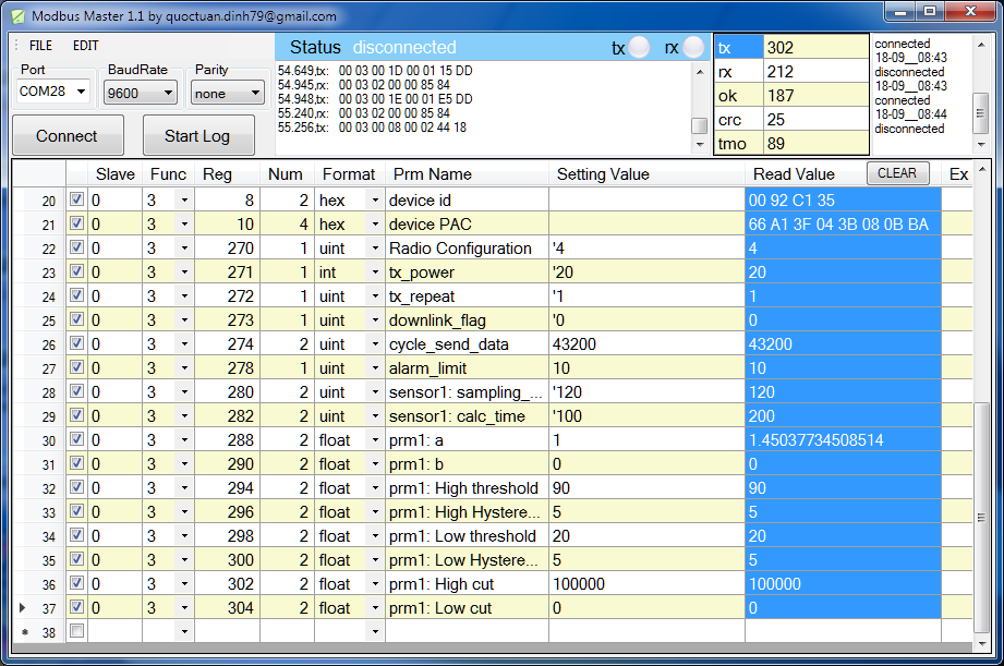
0. Configuration Check List

STEP 2: Check ID and PAC
Use Modbus Configuration Cable to read the ID and PAC values
Refer to register address 8 and 10 (DEC)
STEP 3: Configure the sensor's operating parameters
Configure parameters like cycle send data, alarm, a, b,...
Refer to the configuration section 5 and section 6
STEP 4: Add device to Backend Sigfox
refer to section 5.2 for details
STEP 5: Installation
refer to section 7 for details
Document Ver.
Release Date
Change log
1.0
SEP-2020
- First version for WSSFCEX-PPS
1.1
FEB-2022
- Update information of WSSFCEX-PPS-G-1000
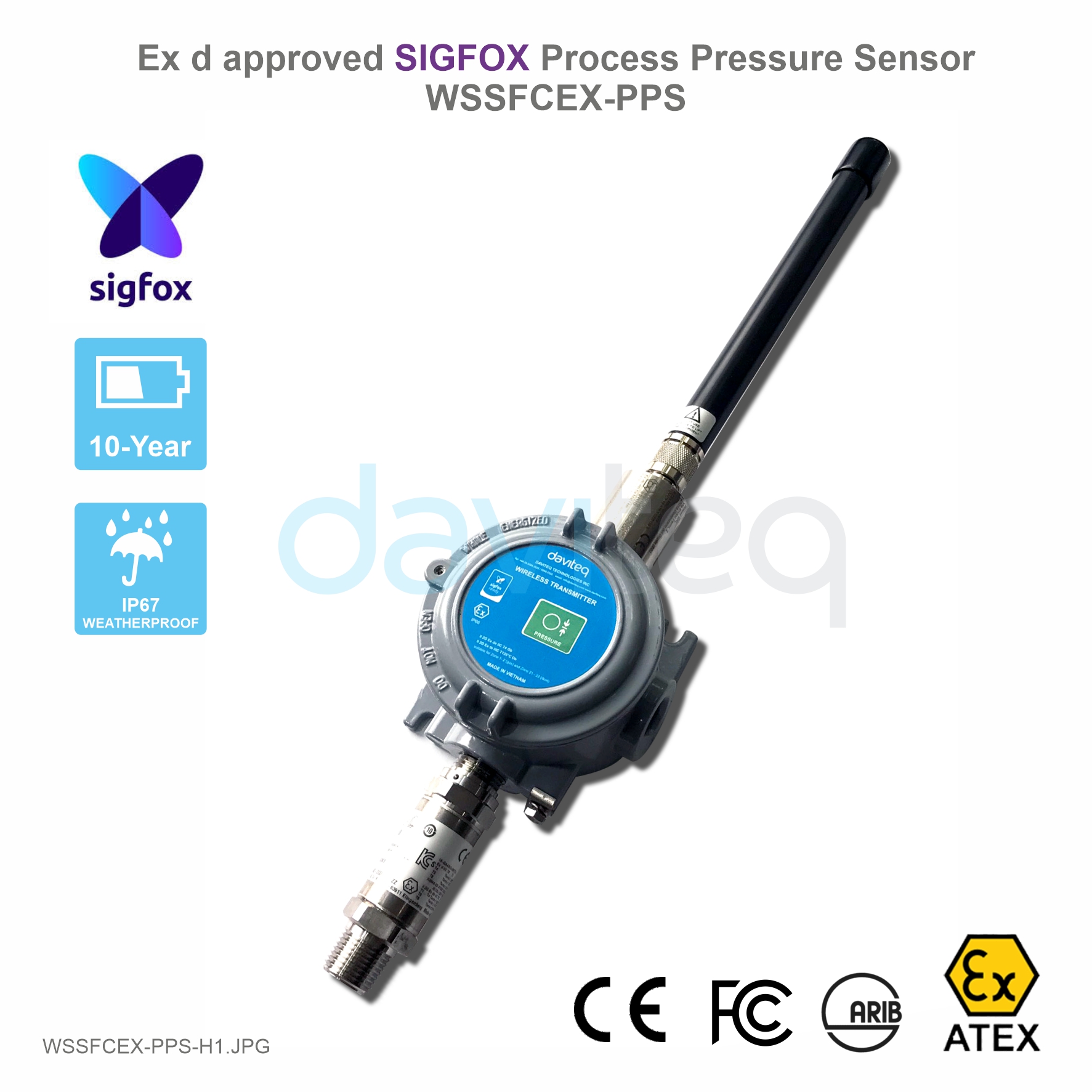
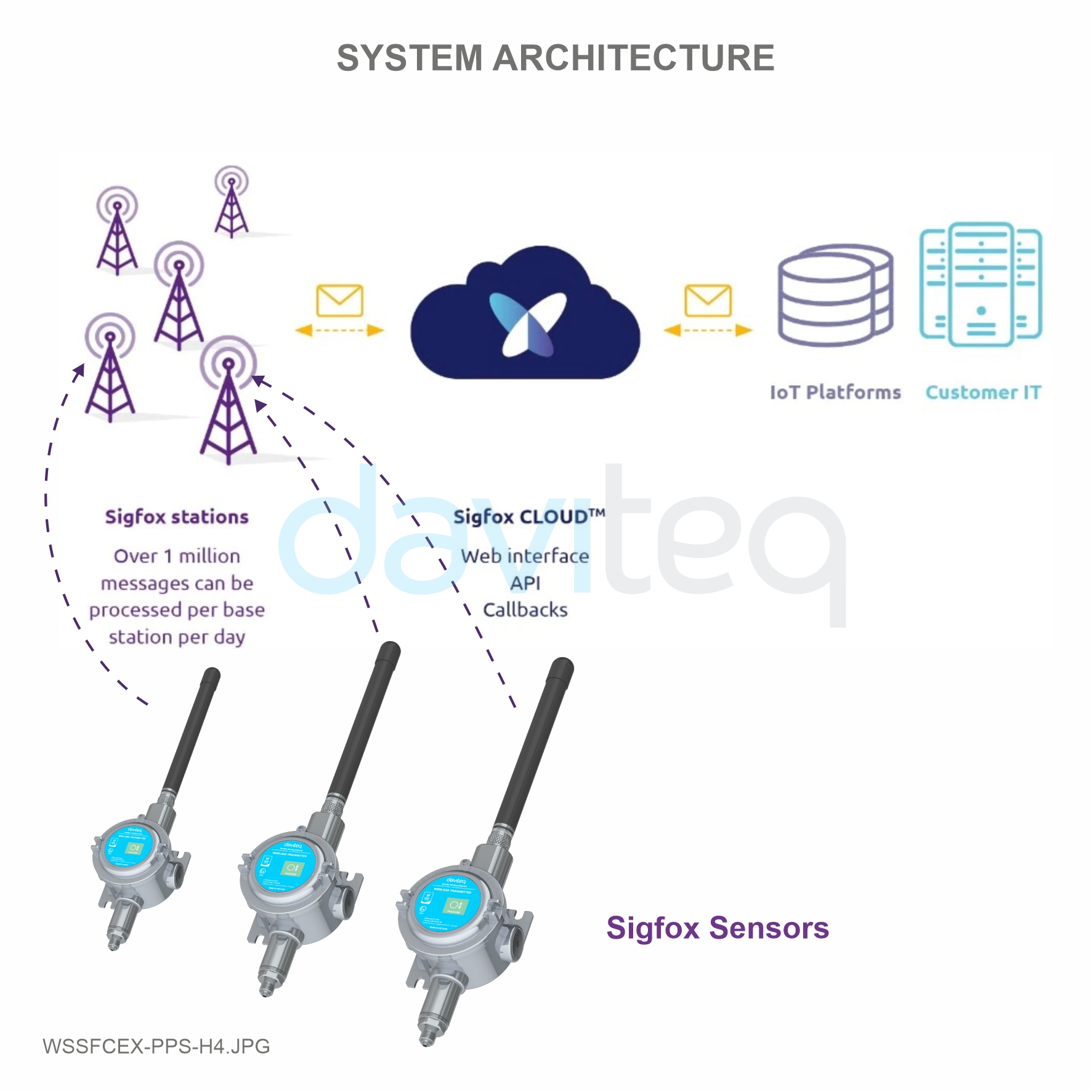
WSSFCEX-PPS is the Sigfox Integrated Process Pressure Sensor with Exd approval for installation in Zone 1, Zone 2 or
Safe Zone, and it has different kinds of measurements, such as Gage/Absolute/Sealed Gage, range -1 .. + 700 bar, high
accuracy, and stability. With Ultra-low-power design and smart firmware allow the sensor can last up to 10 years with
single C battery (depends on configuration). It can supports all regions of Sigfox network in over the World, RC1, RC2,
RC3, RC4, RC5, RC6, RC7. Typical applications are pressure monitoring of oil pipeline, gas pipeline, LPG tank, CNG
tank, etc.
1. Change Log
2. Introduction

Sensor
Advanced PIEZO technology
Measurement range
Select from -1 .. + 1000 bar Gage/Absolute/Sealed Gage
Over pressure protection
1.5 x Span
Accuracy & Stability
0.5% of span, < 0.3% span/year
Wetted parts & Measuring Fluids
304SS/316SS, Any fluid which is workable with materials 304SS/316SS
Fluid Working temperature
0 .. + 80 oC
Process connection
1/2” NPT-male as standard, others please consult factory
Sigfox zones
select RC2-RC3-RC4-RC5 or RC1-RC6-RC7
Antenna
N-male type external Antenna
Battery
02 x AA Type 1.5VDC as standard, working time up to 10 years (depends
on configuration). 02 x Battery AA 3.6V is also available as optional.
ATEX Certificates
IMQ 14 ATEX 005 X, TÜV CY 18 ATEX 0206158 X and IECEx DEK
15.0048X
Marking
ATEX II 2G Ex db IIC T5/T6 Gb and ATEX II 2D Ex tb IIIC T100/T85°C Db
Directive
ATEX 2014/34/EU
Standards
IEC-EN60079-0 IEC-EN60079-1 IEC-EN60079-31
Applicable zones
Zone 1 - 21 (gas) and Zone 2 - 22 (dust)
Ambient working temperature
-40oC..+85oC
Housing
Cast aluminium, powder coated, IP66
Mounting
wall mounting holes
Product dimensions
H100xW100xD80 (excluded antenna)
Net weight
1.5 kgs
Packaging dimension
W160 x D150 x H250 mm
Gross weight
< 1.6 kgs
3. Specification
4. Dimensions
4.1 WSSFCEX-PPS with 0-10 barg version

After 1 minute 30 seconds later the device will send the first data packet and at the same time wait for the downlink
packet from the Base Station.
Then during the operation, there are 03 cases of sending data to base station:
1. When the sensor sampling time interval is reached, the Sigfox node will read the data from Input or sensor
and performing the calculation. After that it will check calculated value with alarm thresholds. If the calculated
was out off the threshold values (Lo or Hi), called alarm, and the number of times of alarm did not pass the limit
of number of alarms, then it will send data to Base station immediately;
2. When the sending time interval is reached, it will send data to Base station immediately, regardless of value;
3. By using the magnet key, the Sigfox node can be triggered to send data to base station immediately. There
will be a beep sound from the buzzer meaning the data has been sent. (Buzzer will be updated in the latest
version)
5. Operation Principle
Upon power on, the Sigfox node has 60 seconds to wait for off-line configuration (via cable with ModbusRTU
protocol)
NOTE:
Once sending the data to base station by this alarm event, the timer of sending time interval will be reset;

EVENT
PRE-CONDITION
ACTION
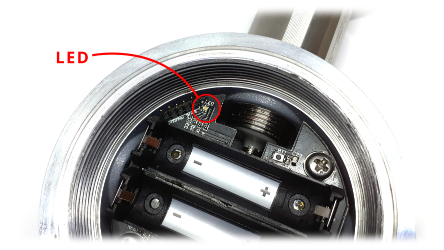
LED STATUS
BUZZER STATUS
ACTIVITIES
POST-
CONDITION
FORCE_DATA
Any state
Move Magnet Key
to contact point of
REED SWITCH.
Buzzer beep 1
time, move
Magnet Key away.
Blink SKY BLUE
Beep 1 time
See FW specs
Back to previous
state
PARAMETERS_UPDATE
Any state
Move Magnet Key
to contact point of
REED SWITCH.
Buzzer beep 1
time, hold Magnet
Key 5s.
Buzzer beep 2
times.
Blink PURPLE
Beep 2 times
See FW specs
Back to previous
state
Whenever the data is sent to base station, the LED will lit with color codes as below:
RC1: RED colour
RC2: GREEN colour
RC4: BLUE colour
NOTE:
Once sending the data to base station by the magnet key, the timer of sending time interval will be reset;
The shortest time interval between the two manual triggers is 15s. if shorter than 15s, there will be no data
sending.
5.1 LED meaning

There are 3 configuration menus: tx_repeat, downlink_flag, radio configuration.
We use the button to enter the menus as follows:
Press and hold the button 2s -> When the Red LED is on, it means entering the tx_repeat configuration menu. Then
release to configure it.
Press to configure. After pressing if the Red LED flashes once, tx_repeat = 0 (send 1 time). After pressing if the Red
LED blinks twice, it is tx_repeat = 1 (send 3 times).
Press and hold the button 5s -> When the Green LED is on, it means entering the downlink_flag configuration
menu. Then release to configure it.
Press to configure. After pressing if the Green LED flashes once, it is downlink_flag = 0 (downlink is not allowed).
After pressing if the Red LED blinks twice, it is downlink_flag = 1 (downlink is allowed).
Press and hold the button 10s -> Blue LED is on, it means entering the Radio Configuration menu. Then release to
configure it.
Press to configure. After pressing if the Blue LED blinks once, it is Radio Configuration = 1. After pressing if the
Blue LED flashes twice, it is Radio Configuration = 2. After pressing if the Blue LED flashes 4 times, it is Radio
Configuration = 4.
There are 3 ways to exit the menu:
Press and hold for 3s, the LED turns off to exit the menu;
Wait 30 seconds, then exit the menu;
Take out the battery, it all starts over (outside the menu)).
The RF transmit power will be automatically set as the max value as allowed by the Zone.
Sigfox Radio Configuration (RC) defines the radio parameters in which the device shall operate: Sigfox operating
frequencies, output power, spectrum access mechanism, throughput, coexistence with other radio technologies, etc.
Each radio configuration includes 4 uplink classes: 0u, 1u, 2u, and 3u.
5.2 Button Function
5.2.1 Menu configuration
5.2.1.1 tx_repeat
5.2.1.1 downlink_flag
5.2.1.1 radio configuration
5.2.2 Exit the menu:
5.3 RC technical details

The Sigfox network globally works within the ranges from 862 to 928 MHz. But not all RCs require such a wide range of
operation.
RC1
RC2
RC4
Uplink center frequency (MHz)
868.130
902.200
920.800
Downlink center frequency (MHz)
869.525
905.200
922.300
Uplink data rate (bit/s)
100
600
600
Downlink data rate (bit/s)
600
600
600
Sigfox recommended EIRP (dBm)
16
24
24
Specifics
Duty cycle
1% *
Frequency
hopping **
Frequency
hopping **
* Duty cycle is 1% of the time per hour (36 seconds). For an 8 to 12 bytes payload, this means 6 messages per hour,
140 per day.
** Frequency hopping: The device broadcasts each message 3 times on 3 different frequencies. Maximum On time
400 ms per channel. No new emission before 20 s.
*** Listen Before Talk: Devices must verify that the Sigfox-operated 200 kHz channel is free of any signal stronger
than −80 dBm before transmitting.
Sigfox’s high limit EIRP recommendation is included in each column although regulations sometimes allow for more
radiated power than the Sigfox recommendation.
Sigfox’s recommendation is set to comply with the Sigfox technological approach of:
Low current consumption
Balanced link budget between uplink and downlink communication
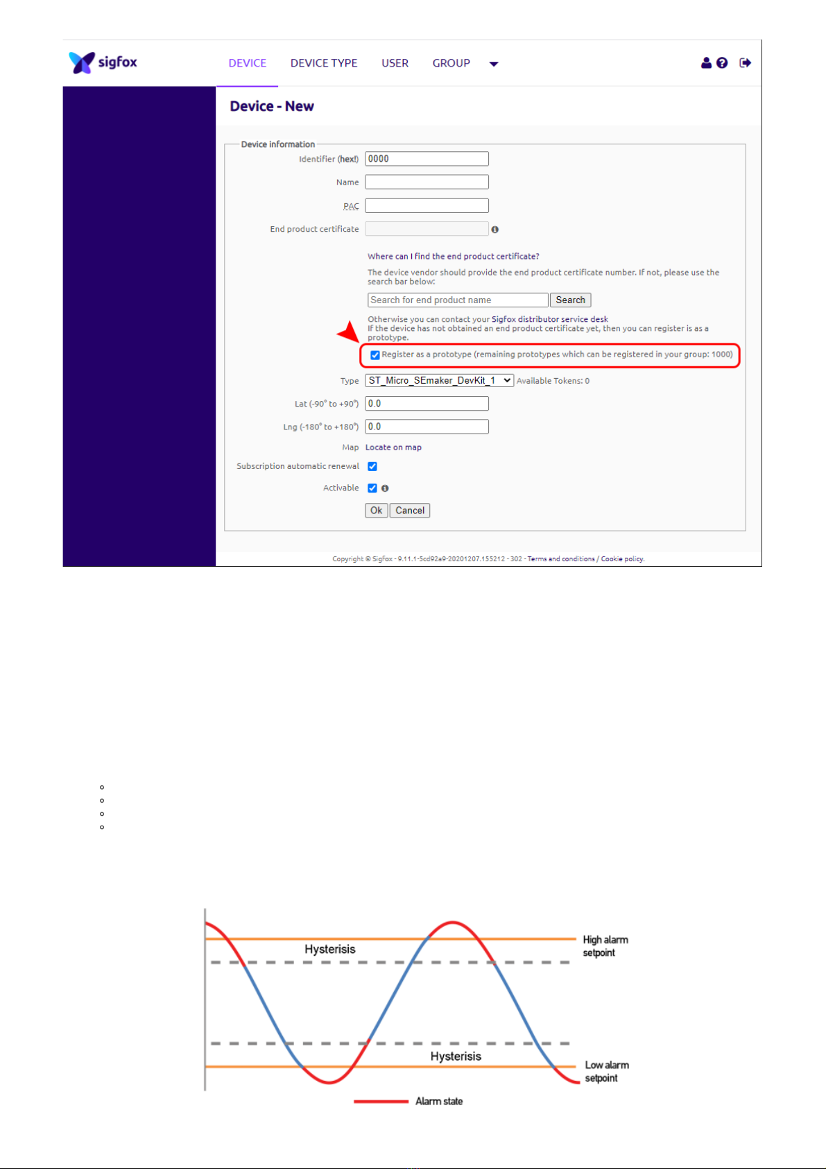
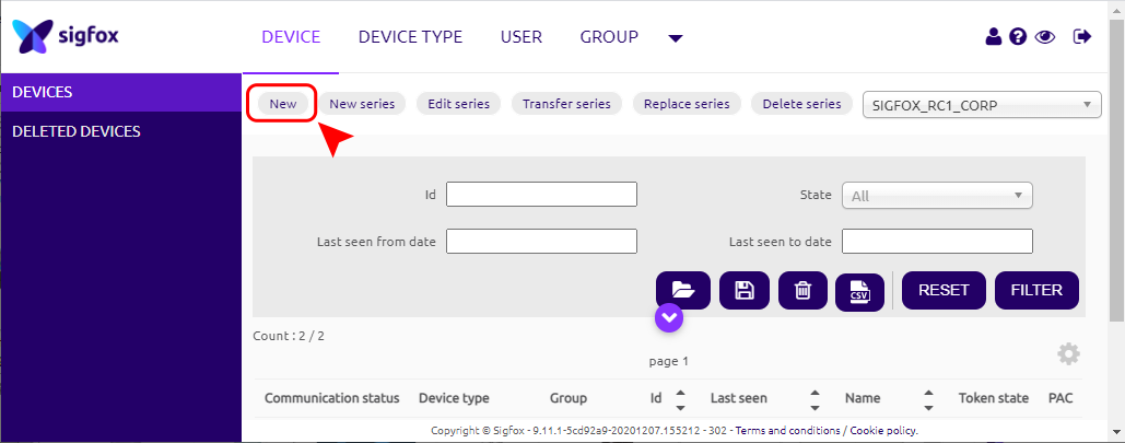
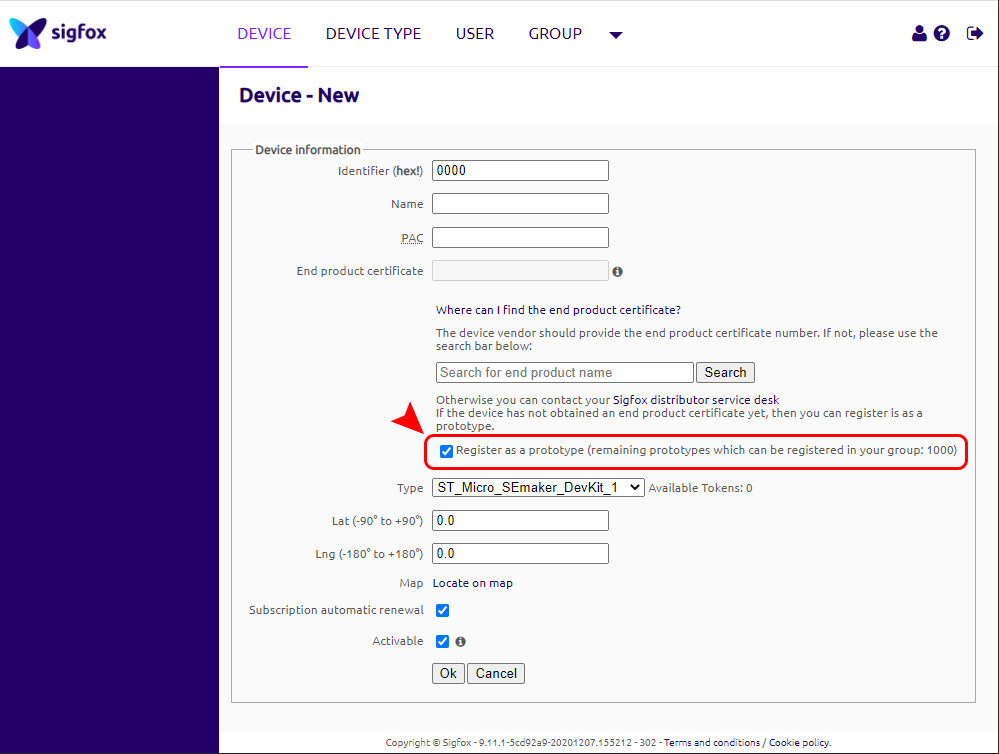
Step 1: Log in to the sigfox backend website
Step 2: Click on Device
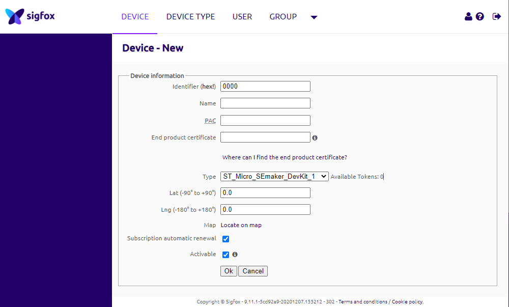
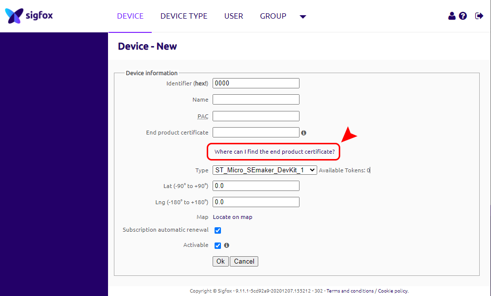
5.4 Add a device to the Backend Sigfox


When the sensor sampling time interval is reached, for example 2 minutes, the Sigfox node will wake up and switch ON
the power supply to supply the energy to external sensor to start the measurement. Depends on the type and
characteristic of external sensor, the sensor will take a certain time to finish the measurement.
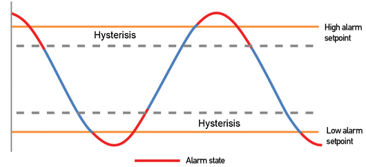
Once reading the value, it can be scaled to any engineering value by the following formula:
Y = aX + b
Where:
X: the raw value from sensor
Y: the calculated value will be sent to Sigfox base station in the payload data.
a: constant (default value is 1)
b: constant (default value is 0)
So, if there is no user setting for a and b ==> Y = X
The Y value will be compared with Lo and Hi threshold. Please refer below the graph of alarm processing.
5.5 Process of measurement

Parameter
Description
Possible values
Default value
Length
(in bits)
HIGH_ALARM_SETPOINT
High alarm setpoint for
calculated value
32-bit float
1000000000
32
LOW_ALARM_SETPOINT_FACTOR
Low alarm setpoint for
calculated value
8-bit unsigned integer
LOW_ALARM_SETPOINT =
HIGH_ALARM_SETPOINT *
LOW_ALARM_SETPOINT_FACTOR
/ 200
0
8
ALARM_ENABLE
Enable/Disable ALARM
event
0b0 = ALARM event is OFF
0b1 = ALARM event is ON
0b0 = ALARM event is OFF
1
ALARM_PERIOD
Period of time to send
ALARM event
0b000 = every 10min
0b001 = every 30min
0b010 = every 1h
0b011 = every 2h
0b100 = every 3h
0b101 = every 6h
0b110 = every 12h
0b111 = every 24h
0b000 = every 10min
3
LED_BUZZER_ENABLE
Enable/Disable LEDs and
Buzzersinteractions for
action
not triggered by the reed
switch
0b1 = LEDs and Buzzers
are ON
1
HEARTBEAT_PERIOD
Period of time to send
HEARTBEAT event
0b000 = every 1h
0b001 = every 6h
0b010 = every 12h
0b011 = every 24h (1 day)
0b100 = every 48h (2
days)
0b101 = every 72h (3
days)
0b110 = every 120h (5
days)
0b111 = every 240h (10
days)
0b011 = every 24h (1 day)
3
MEASURE_PERIOD
Period of time to measure
sensor
0b0000 = every 1s
0b0001 = every 2s
0b0010 = every 5s
0b0011 = every 10s
0b0100 = every 20s
0b0101 = every 30s
0b0110 = every 1min
0b0111 = every 2min
0b1000 = every 5min
0b1001 = every 10min
0b1010 = every 20min
0b1011 = every 30min
0b1100 = every 1h
0b1101 = every 2h
0b1110 = every 3h
0b1111 = every 6h
0b1001 = every 10min
4
TX_REPEAT
Sigfox TX repeat
0b0 = Send RF 1 time
0b1 = Send RF 3 time
0b1 = Send RF 3 time
1
CYCLIC_DATA_PERIOD
Period of time to send
CYCLIC_DATA event
0b000 = every 10min
0b001 = every 30min
0b010 = every 1h
0b011 = every 2h
0b100 = every 3h
0b101 = every 6h
0b110 = every 12h
0b111 = every 24h
0b001 = every 30min
3
DEVICE_RESET
Once this parameter is set,
the device shall restart
once after having received
the Downlink.
0b1010 = 0xA = force
device reset
others = do nothing
0b0000 = do nothing
4
DOWNLINK_TYPE
Downlink type
4-bit unsigned integer
See Sigfox Downlink tab
0b0000
4
The following is the format of payload data will be sent to Sigfox server. Length is 6 bytes, it is future-proof for
expansion to 12 bytes.
5.6 Configuration Parameters
5.7 Payload Data
5.7.1 Payload Fields

Data name
Description
Encoding or Possible
values
Length
(in bits)
EVENT_ID
Unique ID identifying the
device event
4-bit unsigned integer
0 = START_UP
1 = HEARTBEAT
2 = PARAMETERS_UPDATE
3 = FORCE_DATA
4 = CYCLIC_DATA
5 = ALARM
4
HW_VERSION
Indicate HW version
4-bit unsigned integer
1..15
4
FW_VERSION
Indicate FW version
8-bit unsigned integer
1..255
8
LATEST_SIGFOX_DOWNLINK
Latest received and valid
sigfox downlink frame
= Current configuration
64-bit encoded field
See Sigfox Downlink tab
64
HW_ERROR
HW error
0b0 = no error
0b1 = error
1
ALARM
Alarm
0b00 = no alarm
0b01 = low alarm
0b10 = high alarm
0b11 = not used
2
BATTERY_LEVEL
Battery level
2-bit unsigned integer
0..3
2
RAW_VALUE
Raw value of pressure
sensor (12-bit)
16-bit unsigned integer
16
PRESSURE
Scaled value of pressure
sensor
32-bit float
32
TENTATIVE
Tentative number
8-bit unsigned integer
Formula: (8-bit_Tentative
+1)= real_tentative #
Range: 1 to 256
Accuracy: 1
Example: 0b00000111 =
0x7=7=> 7+1
=>tentative # 8
8
Size
START_UP
(led blink WHITE)
Payload
EVENT_ID
HW_VERSION
FW_VERSION
LATEST_SIGFOX_
DOWNLINK
10.0
bits
4
4
8
64
Value
0b0000 = 0
yes
yes
yes
HEARTBEAT
(led blink GREEN)
Payload
EVENT_ID
HW_VERSION
FW_VERSION
LATEST_SIGFOX_
DOWNLINK
10.0
bits
4
4
8
64
Value
0b0001 = 1
yes
yes
yes
5.7.2 Sigfox Uplink Frame Format
PARAMETERS_UPDATE
(led blink PURPLE)
Payload
EVENT_ID
HW_VERSION
FW_VERSION
LATEST_SIGFOX_
DOWNLINK
10.0
bits
4
4
8
64
Value
0b0010 = 2
yes
yes
yes
FORCE_DATA
(led blink
SKY BLUE)
Payload
EVENT_ID
HW_ERROR
reserved
ALARM
BATTERY_LEVEL
reserved
RAW_VALUE
PRESSURE
8.0
bits
4
1
3
2
2
4
16
32
Value
0b0011 = 3
yes
zeros
yes
yes
zeros
yes
yes
CYCLIC_DATA
(led blink
SKY BLUE)
Payload
EVENT_ID
HW_ERROR
reserved
ALARM
BATTERY_LEVEL
reserved
RAW_VALUE
PRESSURE
9.0
bits
4
1
3
2
2
4
16
32
Value
0b0100 = 4
yes
zeros
yes
yes
zeros
yes
yes
ALARM
(led blink
RED)
Payload
EVENT_ID
HW_ERROR
reserved
ALARM
BATTERY_LEVEL
reserved
RAW_VALUE
PRESSURE
9.0
bits
4
1
3
2
2
4
16
32
Value
0b0101 = 5
yes
zeros
yes
yes
zeros
yes
yes
User can set the down link data in Sigfox back-end system in advance, whenever the Sigfox node connected to base
stations and with downlink waiting is enable at that time (one time in 6 hours), the downlink data will be loaded to
5.7.3 Payload for Downlink, length is 8 bytes.
The Sigfox node is only able to receive max 04 downlinks a day, each downlink will be waiting in every 06 hours.

Sigfox node.
The downlink data can be any configuration parameter.
Size
DOWNLINK_TYPE = 0
Payload
HIGH_ALARM_SETPOINT
LOW_ALARM_SETPOINT_FACTOR
ALARM_ENABLE
ALARM_PERIOD
LED_BUZZER_ENABLE
HEARTBEAT_PERIOD
8.0
bits
32
8
1
3
1
3
Value
yes
yes
yes
yes
yes
yes
MEASURE_PERIOD
TX_REPEAT
CYCLIC_DATA_PERIOD
DEVICE_RESET
DOWNLINK_TYPE
4
1
3
4
4
yes
yes
yes
yes
0b0000 = 0
Size
DOWNLINK_TYPE = 5
Payload
PRM_ADDRESS
PRM_LENGTH
PRM_VALUE
reserved
DOWNLINK_TYPE
8.0
bits
8
8
16
28
4
Value
yes
0x02 = 2
yes
zeros
0b0101 = 5
Payload
PRM_ADDRESS
PRM_LENGTH
PRM_VALUE
reserved
DOWNLINK_TYPE
8.0
bits
8
8
32
12
4
Value
yes
0x04 = 4
yes
zeros
0b0101 = 5
Please pay attention when send downlink data. If there was a mistake in sending wrong data, it would
cause the Sigfox node not working properly and user need to configure it by offline cable!!!
6. Configuration
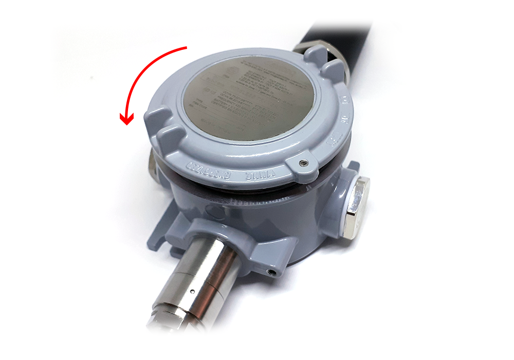
DANGER:
DO NOT OPEN THE COVER AT HAZARDOUS LOCATION!
ONLY OPEN COVER FOR TROUBLE SHOOTING AND CONFIGURATION IN SAFE AREA!

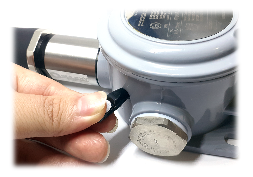
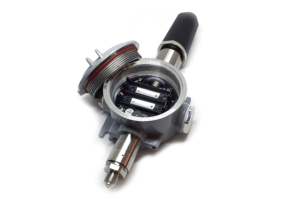
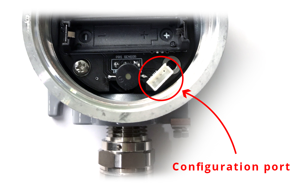
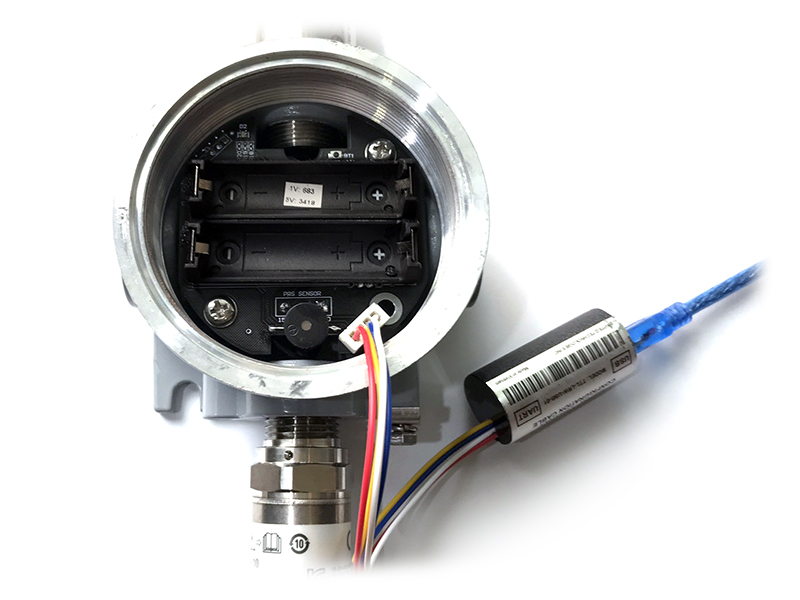
Using the configuration cable to connect to the sensor as below picture.
During connection with Modbus configuration tool, the Sigfox node will send all data in realtime: Battery, Battery level,
Vref, Button status, reed switch status, PCB temperature, Measured value, alarm status.
Step to configure & check data:
Step 1: Install the Modbus Configurator Software in the link below
https://filerun.daviteq.com/wl/?id=qK0PGNbY1g1fuxTqbFW9SXtEvCw7bpc6
Step 2: Plug the configuration cable to computer via USB port and install the driver;
Step 3: Open the housing;
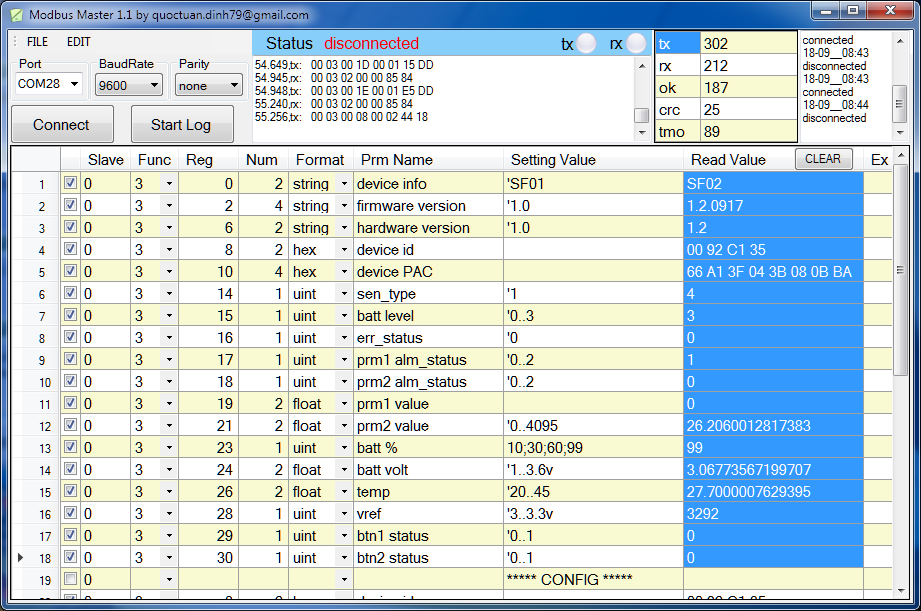
Serial port configuration on computer: 9600 baud, None parity, 1 stop bit.
Reading data by Function 3.
Writing data by Function 16.
NOTE:
The Modbus configuration can be done in the first 60s after power up the Sigfox node. After 60s, if user can not
finish the configuration, user need to reset the power of Sigfox node again, by removing battery in at least 15s.
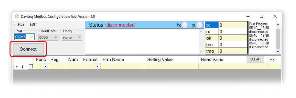
How to use the Modbus configuration software


Step 6: Import the configuration file by importing the csv file: Go to MENU: FILE / Import New / => select the file
with name CONFIGURATION TEMPLATE FILE FOR SIGFOX FW1.9.3.csv (in the link below). Then click Connect;
CONFIGURATION TEMPLATE FILE FOR SIGFOX WSSFCEX-PPS.csv
Here is the table of Data will be read by Modbus tool
Modbus
Register
(DEC)
Modbus
Register
(Hex)
Function
Code
(Read)
Function
Code
(Write)
No. of
Registers
Description
Range
Default
Format
Property
Comment
2
2
3
4
FW_VERSION
string
Read
6
6
3
2
HW_VERSION
string
Read
8
8
3
2
DEVICE_ID
hex
Read
Product ID
10
A
3
4
DEVICE_PAC
hex
Read
Product
PAC
14
E
3
1
SENSOR_TYPE
1-255
uint16
Read
Sensor or
Input Type

Here is the table for Configuration:
Modbus
Register
(DEC)
Modbus
Register
(Hex)
Function
Code
(Read)
Function
Code
(Write)
No. of
Registers
Description
Range
Default
Format
Property
Comment
270
10E
3
16
4
CURRENT_CONFIGURATION
hex
Read/Write
274
112
3
16
1
SERVER_CONFIG
uint16
Read/Write
0: Send to
Sigfox
Network
1: Send to
Dongle
276
114
3
16
1
RADIO_CONFIG
1, 2, 4
4
uint16
Read/Write
RC zones
selection
1, 2 ,4 is
RCZ1,
RCZ2,
RCZ4
277
115
3
16
1
TX_POWER
20
int16
Read/Write
RF Tx
power
278
116
3
16
2
CONSTANT_A
1
float
Read/Write
Constant a
for scaling
measured
value
280
118
3
16
2
CONSTANT_B
0
float
Read/Write
Constant b
for scaling
measured
value
282
11A
3
16
2
HIGH_CUT
1000000000
float
Read/Write
High cut
value for
calculated
value
284
11C
3
16
2
LOW_CUT
-
1000000000
float
Read/Write
Low cut
value for
calculated
value
286
11E
3
16
2
SENSOR_BOOT_TIME
200
uint32
Read/Write
Boot time
of
sensor/input,
in ms

To maximize the distance of transmission, the ideal condition is Line-of-sight (LOS) between the Sigfox sensor and
Base station. In real life, there may be no LOS condition. However, the Sigfox sensor still communicate with Base
station, but the distance will be reduced significantly.
7. Installation
7.1 Locate the good place for Radio signal
ATTENTION:
DO NOT install the Sigfox sensor or its antenna inside a completed metallic box or housing, because RF signal
can not pass through metallic wall. The housing is made from Non-metallic materials like plastic, glass, wood,
leather, concrete, cement…is acceptable.

Consider to use the isolation valve 1/2" or 1/4" to isolate the media and the sensor during maintenance;
Fully closing the isolation valve during installation and maintenance the sensor;
Fully open the isolation valve during normal operation;
There are two ways of process mounting as below.
The total weight of the sensor MUST be within the permitted load of the pipe to be installed;
Consider to build the support for the pipe if the sensor weight is larger than the permit;
Below picture shown without the isolation valve, but we highly recommend to use isolation valve.
7.2 Process mounting
WARNINGS:
1. Please make sure the fluid is suitable with the wetted materials of the sensor. Please refer sensor
specification;
2. Please make sure the operating temperature and pressure is suitable with the sensor. Please refer sensor
specification;
3. Prepare the professional tools for installation. The inappropriate tools may cause damage to the sensor.
DANGER:
1. The installer need to be equipped with full Safety gears during installation, such as safety glasses, safety
shoes, safety cloths, safety mask...Please follow the safety instructions of the installation site;
2. The installer must be qualified for this installation job;
3. The installer must be permitted by Site's owner for performing the installation;
4. The working conditions in hazardous areas (toxic gases, explosive atmosphere, high pressure, high
temperature...) must be highly attention and follow the site's owner instruction strictly.
DO NOT OPEN THE COVER OR REPLACE/INSERT BATTERIES IN THE HAZADOUS AREAS
7.2.1 Mounting direct on Pipe
This manual suits for next models
3
Table of contents
Other Sigfox Accessories manuals


Popular Accessories manuals by other brands


Loup Electronics
Loup Electronics Weighlog 100 User guide and installation manual

Pepperl+Fuchs
Pepperl+Fuchs R1000 Series manual

Philips
Philips DLA67009D brochure

Rockwell Automation
Rockwell Automation 42JT-C2LAT1-A2 installation instructions

Alula
Alula NanoMax RE322 instructions

SICK
SICK OD2000 operating instructions