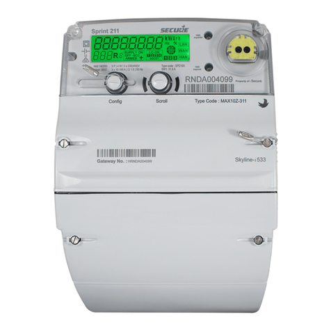
Secure Sprint 211 User manual

Sprint 211 electricity meter with
Skyline- i 533/033 communication module
Installation Manual
BGX701-160-R01

Commercial and Confidential
© 2018, SIHPL. All rights reserved. E&OE.
Sprint 211®and Skyline-i 533/033®are registered trade names of Secure Meters Ltd.
Other product names are trademarks or registered trade names of their respective owners.
As part of Secure Meter’s continuous endeavour to improve product design, specifications mentioned are liable to change.
Page 2 of 48 Sprint 211 Installation Manual BGX701-160-R01

Table of Contents
Important...........................................................................................................................................5
Disclaimer .........................................................................................................................................6
Precautions and safety practices....................................................................................................6
Terms and abbreviations..................................................................................................................7
1Product overview and operating principle................................................................................8
2Product description....................................................................................................................9
2.1 Sprint 211 main features ...............................................................................................................................9
2.2 Information printed on Sprint 211 front cover..............................................................................................11
3Meter specifications..................................................................................................................12
3.1 General specifications.................................................................................................................................12
3.2 Firmware......................................................................................................................................................14
3.3 Handling, storage and operating conditions................................................................................................14
3.4 Standards and external certification............................................................................................................15
3.5 Connection terminals...................................................................................................................................15
3.5.1 Connection diagram, with disconnect and LC..............................................................................15
3.5.2 Connection diagram, with disconnect and without LC..................................................................15
4Installation and mounting details ............................................................................................16
4.1 Lifting the meter...........................................................................................................................................16
4.2 Unpacking the Meter...................................................................................................................................16
4.3 Precautions & safety practices....................................................................................................................16
4.4 Quick start ...................................................................................................................................................16
4.4.1 Getting started ..............................................................................................................................16
4.5 Dimensions and mounting arrangements ...................................................................................................18
4.6 Pre-installation checklist..............................................................................................................................21
4.6.1 Tools and accessories..................................................................................................................21
4.6.2 Selecting an appropriate mounting location .................................................................................21
4.6.3 Selecting suitable mounting screws .............................................................................................21
4.6.4 Selecting the cable .......................................................................................................................22
4.7 Installation procedure..................................................................................................................................23
4.7.1 The groundwork............................................................................................................................23
4.7.2 Mounting the meter.......................................................................................................................23
4.7.3 Preparing cables for termination...................................................................................................24
4.7.4 Making connections......................................................................................................................25
5Display and button details........................................................................................................27
5.1 Using the display.........................................................................................................................................29
5.1.1 Display types and viewing arrangements.....................................................................................29
6Appendix 1: Commissioning....................................................................................................31
BGX701-160-R01
Sprint 211 Installation Manual Page 3 of 48
6.1 ‘Without WAN’ Scenario..............................................................................................................................38
6.2 ‘With WAN’ Scenario...................................................................................................................................39
7Appendix 1: Fitting an external antenna .................................................................................41
8Appendix 2: Replacing the communication module...............................................................43
9Appendix 3: Opening and fitting the secondary terminal cover............................................ 45
Notes ...............................................................................................................................................46
Notes ...............................................................................................................................................47
Page 4 of 48 Sprint 211 Installation Manual BGX701-160-R01

Important
As part of Secure Meters continuous endeavour to improve product design, the specifications mentioned in this
manual are liable to change anytime and therefore availability of features is product build specific.
Specifications / features listed in this document are the most advanced available with Secure Meters on the date
of release of this document, and hence should not be considered as default. Availability of all or some of the
same depends upon the product builds and may not be readily available. Sales team should be contacted for
queries, if any.
No part of the manual, or its content thereof, must be published, distributed, scanned or copied, in either
electronic form or otherwise, without prior information and express consent of Secure Meters.
While all efforts have been made by Secure Meters to minimize errors, some errors may inadvertently exist.
Secure Meters undertake to correct such errors wherever possible, and request feedback from users in this
regard.
Secure Meters reserve the right to alter some or whole of the specifications mentioned in this document without
any prior notice.
For any queries or clarifications, the user is requested to email the Secure Meters’ support team at
tech.support@securemeters.com
In most countries, electrical installations comply with more than one set of regulations issued by National
Authorities or by recognized private bodies. It is essential to take into account these local constraints.
Secure Meters have duly conducted product quality tests as per regulations based on the observance of
rigorous safety rules in the design and realization of the product.
In order to prevent tampering, the meter should be appropriately sealed after installation. Inappropriate handling
of the seal may cause damage to the meter thus creating a false impression of being tampered with.
Please take note of the warning and caution icons presented in this manual as follows:
This icon indicates the existence of dangerous electrical voltage. These
operations must only be performed by qualified personnel.
Attention
This icon warns the user to take special precautions whilst performing an
operation. The procedure must be followed as described in the manual.
Possible
Electric Hazard
BGX701-160-R01
Sprint 211 Installation Manual Page 5 of 48

Disclaimer
Secure Meters assume no responsibility for damage caused to the meter under the following circumstances:
Irregular maintenance / improper installation
Imprudence or carelessness during installation
Normal (or abnormal) wear and tear of insulation
Accidental contact with hazardous elements
Immersion of meter in water
Handling of meter by unauthorised persons
Handling of meter by inebriated persons
Precautions and safety practices
This product must be installed and serviced only by trained personnel. We strongly recommend
reading the ‘Sprint 211 installation manual’ thoroughly before installing the product.
Energy meters are generally installed in electrically hazardous areas. To minimise the risk of
electrical shock, stay away from loose or exposed electrical connections. If there is loose or exposed
electrical wiring near the meter, initiate appropriate preventive measures.
The electrical installation of electronic meters at a site requires an adequate understanding of all
governing rules and regulations.
Keep the meter away from fire, rain and direct exposure to water.
The meter may be damaged, either in part or completely, if it falls from a height.
It is recommended to immediately cut off the electricity supply upon occurrence of a fault within the
meter.
Ensure that the load does not exceed the current range specified on the rating plate.
Appropriate fuses and circuit breakers must be used in accordance with the rating of the meter.
Secure Meters recommend regular installation checks to be carried out, especially when product is
installed at locations posing high risk of degradation or corrosion, such as under direct strong
sunlight, areas with high ambient temperature and little ventilation, areas near heat sources such as a
furnace, areas where the meter is regularly exposed to chemical fumes, etc.
When enabling the external antenna always ensure that it has been plugged into the SMA connector
under the module.
To ensure optimal performance of the radio system with the meter, the radio antenna must be fitted
externally if the meter (or modem) is installed inside a metal enclosure.
Always refer to installation & associated documentations and follow the instruction and the practices
described. Manual should be strictly referred for details wherever the caution symbols are used on
the product.
If the meter is not used in the manner specified in the manual, the protection provided by the meter
may be impaired.
Safety practices must be followed as open position of the supply or load control switch does not
provide isolation from the mains network.
The installer is responsible for coordinating the rating and the characteristic of the supply side over
current protection devices to the maximum current rating of the metering equipment. Refer section
General for details.
Page 6 of 48 Sprint 211 Installation Manual BGX701-160-R01

Terms and abbreviations
Terms used in the manual
Manual connection : Connecting supply using the push buttons.
Remote connection/
disconnection : Connecting/disconnecting supply using remote commands.
Local disconnection : Self-disconnection of meter’s supply switch due to load limit.
Sprint 211 : Smart electricity meter with a display push buttons.
Skyline-i 533/033 : Internal 3G module mounted inside the communication module cover of
Sprint 211 electricity meter. The manual refers to it as the communication
module.
Abbreviations and Acronyms
Acronym Description
TBC Terminal Block Cover
3G Third Generation of broadband cellular networking
PC-FR Fire Retardant- Poly Carbonate
LCD Liquid Crystal Display
LED Light Emitting Diode
SMA Sub-Miniature version A
WAN Wide Area Network
HAN Home Area Network
ID Identity
CT Current Transformer
IHD In-Home Display
IEC International Electro-technical Commission
BGX701-160-R01
Sprint 211 Installation Manual Page 7 of 48

1 Product overview and operating principle
Sprint 211 is a three phase, single element electricity meter that supports both Credit and Prepayment (or Pay
As You Go (PAYG) modes of operation for Smart Metering. It is available in two variants one with load control
feature and other without this feature. Please check the rating plate to know your version of the meter. The
meter supports 230V (+20%/– 20%) connection with the current of 10-100A. It is used with a Skyline-i 533/033
intimate modular communication module.
Skyline-i 533 communication module supports 3G (with fallback on GPRS).
The communication module sits on front belly of the meter cover. It serves as the communication gateway to the
Head End System (HES) via a Wide Area Network (WAN) and other smart metering devices via a Home Area
Network (HAN). The modular communication design provides the flexibility to upgrade or change the meter’s
communication technology without the need to remove the meter or break metrological seals. The
communication module connects the meter to HES over 3G. This communication provides remote data transfer
between the meter and HES either as per the request or according to the schedule. The Zigbee® module
connects the communication module with other HAN devices –In Home Display (IHD).
Figure 1: Operational scenario (with Skyline-i 533/033)
It has an 1107 optical communication port for local communications and a user interface consisting of two push
buttons which allows the user to select and display the data.
Commands or changes of configuration can be delivered to the meter in the form of authorised messages or
UTRNs. UTRNs are encrypted codes that are valid only in the meter for which they are generated.
An integrated 100A mains supply contactor is provided which can be used for disconnecting/ reconnecting
mains supply. Supply disconnection / reconnection can be done remotely over the WAN or locally. Mains
frequency based clock or a battery-backed internal clock maintains the meter’s date and time. Removal of the
terminal cover and main cover is detected and logged in power-on condition.
Internal sensors monitor external magnetic fields allowing magnetic events to be logged and reported.
In addition, a load control switch rated at 31.5 A (variant specific) is integrated into the meter which controls
loads connected to the auxiliary load terminal of the meter.
Notes:
The operational scenario is similar for Skyline-i 033 except that the communication with IHDs over
HAN is not supported.
Some of the functionalities / features will be applicable depending upon the availability for load control
switch in the product.
Page 8 of 48 Sprint 211 Installation Manual BGX701-160-R01

2 Product description
This section describes the salient features of the product.
2.1 Sprint 211 main features
BGX701-160-R01
Sprint 211 Installation Manual Page 9 of 48

Figure 2: Sprint 211 electricity meter
Fixed Plate–Information is fixed and is common for all meters of this type.
1. LCD display - A large multi-segment LCD supporting alpha-numeric characters displays the information
and values for various electrical parameters recorded by the meter.
2. Push Buttons -Two push buttons Left and Right, allow interactions with Sprint 211. These buttons are
used for various user operations such as display navigation, boost operation etc.
3. Communication Module –To facilitate AMI communication, Sprint 211 provides a modular compartment;
into which, a communication module can be fitted as required.
4. Metrological LED (Fixed) - This LED is provided on the meter main face plate and flashes according to the
rate of energy consumption measured by the meter. It is used for testing the accuracy of the meter and as a
visual indication of the rate of energy consumption.
5. Metrological LED (Configurable) - This LED is provided on the meter main face plate and by default it is
configured for Reactive Import Energy consumption.
6. 1107 Port – The communication with the external world is supported through 1107 optical port. The port
supports a maximum data rate of up to 9600 baud.
7. Meter Base and Front Cover -The base or enclosure of the meter is made of a high-grade fire-retardant
poly-carbonate. The front cover, made of the same material, is fastened to the base with screws. A sealing
arrangement is provided to prevent tampering.
8. Sealable Screws -These screws facilitate the sealing arrangement necessary after the installation of the
meter in the field.
9. Supply LEDs: Two supply LEDs are provided on the meter main face plate for indicating main switch status
such as OFF, ON and ARM state.
10. Terminals and Terminal Block - A terminal block, capable of sustaining high temperature, is provided in
the meter with adequate provisions for connecting wires to the meter.
11. Secondary Terminal Cover- The secondary terminal cover provides additional protection for the live
terminals of the meter and keeps them inaccessible even after removal of the main terminal cover.
12. Terminal Cover–The terminal cover protects the terminal connections from tamper or interference,
provides safety from hazards and provides security of add-on modules.
13. SMA connector for external antennas - SMA (Sub-Miniature version A) connectors are available under
the module to connect a compatible external antenna (WAN and HAN) on the Sprint 211.
14. RJ 45 Port: This port is not accessible to the user.
Page 10 of 48 Sprint 211 Installation Manual BGX701-160-R01

15. 31.5 Ampere load contactor (variant specific)- This is provided in Sprint 211 to support basic load control
functions such as load switch actions, switch time randomisation and load cycling.
16. Phase Selection Sockets – Either of phases i.e. A, B or C can be used to energise the auxiliary load
connected to L1 with the help of a phase selection provision provided on Sprint 211’s terminal block. This is
done by tightening the screw provided in any ONE of the phase selection sockets above each phase.
CAUTION – DO NOT connect the auxiliary load in parallel to more than one phase at a time. This will lead to a
short circuit. For a given meter installation, the auxiliary load can be connected to only one phase. This is a
variant specific feature.
2.2 Information printed on Sprint 211 front cover
Figure 3: Information on the Sprint 211 front cover
Lithium battery
Double insulation
symbol
Meter name
Manufacturer’s
trademark
Type Code
Barcode for
meter serial
number
Meter serial
number
As per load
control variant
Rated operating voltage
Current rating
Class index, Frequency
Temperature
Year of manufacture
BGX701-160-R01
Sprint 211 Installation Manual Page 11 of 48

3 Meter specifications
This section describes the mechanical, electrical, compliance, hardware and environmental specifications for
the Sprint 211 meter.
3.1 General specifications
S. No. Specification Description
1 Mechanical Dimensions (mm) 221 (H) x 180 (W) x 116 (D)
Weight 2.2 kg approx (Actual weight may vary with variants)
Mounting Projection type
Front cover Translucent PC-FR grade V0
Base Opaque, PC-FR material
Communication module
cover Opaque, PC-FR material
Terminal cover
Opaque, PC-FR material
Secondary terminal
cover
Opaque, PC-FR material
Terminal block Opaque 10% glass filled PC-FR grade V0, matt finish
Rating plate
Opaque, PC-FR material
Main load terminal
screws Nickel plated M8 brass grub, optional nickel plated M8
Pozidriv PZ#3
Current bus-bars
(Internal) Made of copper with tin plating
Minimum bore diameter
for main terminals 11 mm, suitable for 35 mm2 multi-strand copper cables
Sealing Provision •2 seals at the back of the meter (upper screws)
•2 seals under the terminal cover
•2 seals on the terminal cover
•1 optional seal for configuration button
•2 seals on the module
Sealing screw Captive type, made of brass, sealing hole diameter 2mm
Page 12 of 48 Sprint 211 Installation Manual BGX701-160-R01

Display Super-twisted Nematic (STN) LCD with backlight
2 Electrical Connection, Supply 3 Phase, 4 Wire, Direct Connected
Voltage measuring
element
Voltage divider
Current measuring
element
CT
Measuring Elements
Three
Reference Voltage
(Supply Voltage)
230V± 20%
Reference current range 10A Ib, 100A Imax (per phase)
Frequency 50 Hz ±5%
EMC/Electric Surge BS EN 50470-1, 50470-3
Metrology LED
Two LEDs, 1000 pulses/unit
RJ45 port/connector Option not accessible
Load control contactor 230 VAC, 100A
Non-volatile memory 2MB Flash, Data retention up to 15 years
Connecting Cables
(Recommended -As per
service and installation
practices)
Type PVC, V-75,
Copper
PVC, V-90,
Copper
Size 35mm2 for 100A 35mm2 for 100A
Voltage rating 600/1000V 600/1000V
Normal
temperature rating 75°C 90°C
Communication module Nominal Voltage: 4V(+/-0.1V)
Maximum load: 1.4A (Peak)
3 Protection Dielectric Strength •AC voltage withstands as per BS EN 50470-1
•Impulse withstand as per BS EN 50470-1
4 Compliance Metrology BS EN 50470-1, 50470-3 Class B
Power Consumption
BS EN 50470-1, 50470-3
BGX701-160-R01
Sprint 211 Installation Manual Page 13 of 48

3.2 Firmware
The meter supports the following firmware:
•Metrology firmware
Metrology firmware controls the measurement functions. It also provides an operating system for the
application firmware. This firmware is fixed and cannot be upgraded.
•Application firmware
Application firmware controls the functions of the meter outside of metrology. It is possible to remotely
upgrade this firmware to change the meter operation. Upgrading or updating the firmware will not affect
the meter data unless the update involves changing the parameters of such data. Information related to
load survey, transactions, events and storage or contents in billing registers are not affected during these
upgrades.
Note: The current firmware name and version are available in meter readings and on the meter’s display.
3.3 Handling, storage and operating conditions
The Sprint 211 meter is an electronic device containing delicate components, which should be handled carefully
during transit, storage, and installation. The meter should be protected from physical vibration and shocks.
Wherever possible the meter should be kept in its original packaging until it is installed at the customer’s site.
Temperature and humidity must be maintained within the limits expressed in the above table.
Proper installation and removal procedures should be followed, in order to prevent damage or injury. Physical
damage to the meter’s case could indicate damage to internal components. Under no circumstances should an
attempt be made to install a damaged meter.
A visual inspection should be performed before installing the meter. The following should be checked, as a
minimum:
Protective class
II
5 Environmental Operating Temperature
as per IEC standard Range
Indoor Meter
Specified operating range -10 °C to +40 °C
Limit range of operation -25 °C to +55 °C
Limit range for storage -25 °C to +55 °C
Limit range for
transportation -25 °C to +70 °C
Operating Humidity Annual mean < 75 %
For 30 days, spread in a
natural manner over one
year
95 % (non- condensing)
Occasionally on other days 85 %
Page 14 of 48 Sprint 211 Installation Manual BGX701-160-R01

•No evidence of external damage or missing parts
•No missing or damaged wiring
•No evidence of overheating
Ideally the meter should be stored and operated in a dry, well ventilated, climate-controlled building. Rapid
changes in temperature and humidity should be avoided.
3.4 Standards and external certification
The Sprint 211 meter with internal communication module conforms to the following standards:
Table 1: Standards
Electrical requirements
MID Approval
0120/SGS0337
3.5 Connection terminals
The following diagram shows the internal connection for two build types of the Sprint 211.
3.5.1 Connection diagram, with disconnect and LC
3.5.2 Connection diagram, with disconnect and without LC
BGX701-160-R01
Sprint 211 Installation Manual Page 15 of 48

4 Installation and mounting details
The installation of Sprint 211 must be performed with extra care and attention. The existence of dangerous
electrical voltage may be fatal. Hence, these operations should be performed only by skilled personnel.
4.1 Lifting the meter
Meter should be handled with care while lifting and transferring from one place to another.
4.2 Unpacking the Meter
The meter needs to be unpacked from its original packing before installation.
Open the box cover and take out the meter vertically.
4.3 Precautions & safety practices
•While working with live equipment, always wear hand-gloves made of an insulating material.
•Disconnect the mains supply before meter installation.
•Ensure that there are no loose or exposed electrical connection(s) or uninsulated, live wires near, or at,
the installation site.
•Follow standard precautions to prevent damage due to electrostatic discharge while handling external
antenna port.
If necessary, use fast-drying, commercially available insulation coating to cover the exposed
electrical wiring.
•Always use proper tools and equipment.
•Never use damaged tools.
The use of damaged tools is major cause of installation-related accidents. Improper tools may
cause an irreversible damage to the meter and its accessories.
•When the meter is being installed within the premises like an apartment (inside), always install it at a
safe height which allows clear vision of meter display and easy access to meter buttons.
•Never connect a load which makes the meter operate outside its specified limits.
Operating current range of meter is specified on the rating plate.
4.4 Quick start
This section is intended only for experienced field staff with prior exposure to energy meter installation. It
summarizes the recommended sequence of actions for installation.
4.4.1 Getting started
1. Select an easily accessible mounting location for the meter. When the selected location has multiple
meter installations, identify the correct consumer installation.
Page 16 of 48 Sprint 211 Installation Manual BGX701-160-R01

2. Ensure safe working conditions near the installation location.
3. Check whether the consumer installation can be isolated safely from the mains.
4. Check for the polarity of the supply.
5. Label the wiring for correct connections.
BGX701-160-R01
Sprint 211 Installation Manual Page 17 of 48

4.5 Dimensions and mounting arrangements
This section displays the dimensions of the product in various views. The meter terminal dimensions are also
provided here. Details such as possible vertical and horizontal mounting positions are included to ease the
installation process.
Page 18 of 48 Sprint 211 Installation Manual BGX701-160-R01

Figure 4: Terminal connections
Sprint 211 supports various mounting options which include arrangements to substitute any currently installed
meters too. The figure below displays the rear view fixing dimensions in mm.
BGX701-160-R01
Sprint 211 Installation Manual Page 19 of 48

Figure 5: Dimensions and Mounting Details
All the possible mounting options are described in the table below:
Table 2: Sprint 211 Mounting measurements
Options Mounting
arrangement holes Vertical distance (mm) Horizontal distance (mm)
Option 1
1, 2, 3
165
144
Option 2
1, 4, 5
175
144
Page 20 of 48 Sprint 211 Installation Manual BGX701-160-R01
Table of contents
Other Secure Measuring Instrument manuals

Secure
Secure Elite 440 User manual

Secure
Secure PADS-2 User manual

Secure
Secure BGX501-806-R02 User manual

Secure
Secure SSP 302 Operating instructions

Secure
Secure Premier 300 User manual

Secure
Secure Premier 300 Instruction manual

Secure
Secure TRACKSO ELITE 103-2 User manual

Secure
Secure Liberty EG4v12 Operating manual

Secure
Secure Liberty 100 Product manual

Secure
Secure APEX 100 User manual