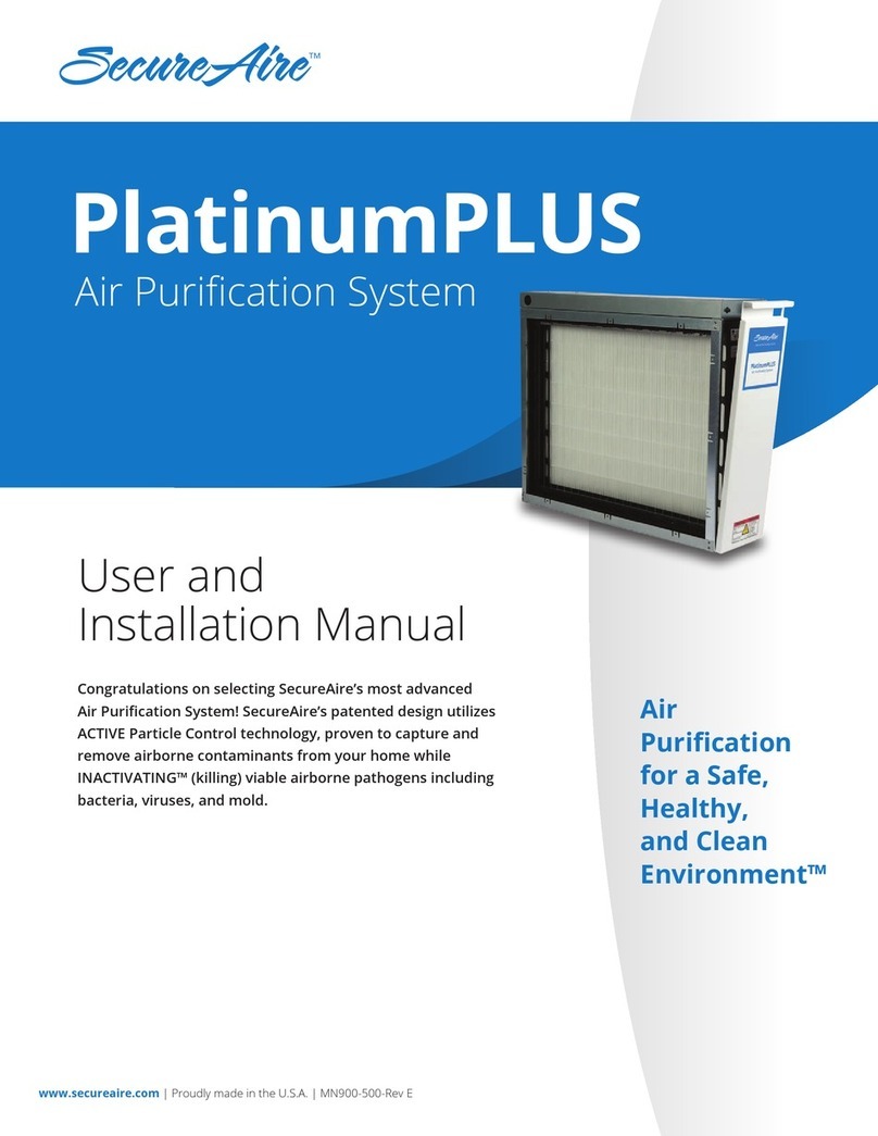
SecureAire ACS User manual

www.secureaire.com | Proudly made in the U.S.A. | ACS Slim Line-Rev A
Installation, Operating
and Maintenance Guide
Congratulations on selecting the most advanced
RTU Air Purication System!
SecureAire’s Patented ACTIVE Particle Control™ Technology
removes airborne contaminants while INACTIVATING™
(killing) viable airborne pathogens including bacteria,
viruses and mold.
Air
Purication
for a Safe,
Healthy,
and Clean
Environment™
Roof Top Unit (RTU) Air Purication System
ACS – Slim Line
System

www.secureaire.com | Proudly made in the U.S.A. | ACS – Slim Line-Rev A2
D
C
B
A
Legal Notices
The information contained in this document
is subject to change without notice.
This document contains proprietary information
that is protected by copyright. All rights are reserved.
No part of this document may be photocopied,
reproduced, or translated to another language
without the prior written consent of SecureAire
SecureAire Technologies, LLC
1968 Bayshore Blvd, Suite 207
Dunedin, Florida 34698
Phone: 813-300-6077 | www.secureaire.com
Technical Support
Please contact us at 813-300-6077 with any
questions or problems.
Printing History
This manual was rst printed in June 2021. The
edition number will change when a new edition
is printed. Minor changes may be made at reprint
without changing the edition number. The part
number will change when extensive changes
are made.
Preface
System Overview
ACS – Slim Line System Parts List
Included:
• A: Protection Plate
• B & C: Slim Line Filter Unit(s)
• D: Connection Plate with high voltage wire(s)
• E: SCM-300C Unit(s) Power Supply
• F: Safety Interlock Door Switch(es)
Not included:
• Electrical conduit, wiring and conduit junction boxes
• All appropriate control wiring
• 2” U - channel (Nominal 2” ID, and 0.45” ID rise)
E
F

www.secureaire.com | Proudly made in the U.S.A. | ACS – Slim Line-Rev A 3
ACS – Slim Line System Installation
Installation Overview
The ACS – Slim Line System should be installed by an experienced HVAC mechanical contractor
and a licensed electrician. The installation consists of the following four phases:
• Phase 1: Removal of the existing 2” mechanical lters.
• Phase 2: Installing the ACS – Slim Line components.
• Phase 3: Connecting the ACS – Slim Line components and system power.
• Phase 4: Testing the system.
Installing the SecureAire ACS – Slim Line System
Phase 1: Removal of the existing 2” mechanical lters
STEP 1: Ensure that you have measured the existing mechanical lters and have ordered the
appropriate size SecureAire ACS – Slim Line Filter Units.
STEP 2: Check the existing 2” racking system for damage and/or adjustments and perform
the necessary changes.
STEP 3: Plan and install blank-os if and where required.
Phase 2: Installing the ACS – Slim Line Components
The ACS – Slim Line System has been designed for easy installation. Basic mechanical tools and skills
are needed to install the ACS – Slim Line Filter Units, Power Supply, and Safety Interlock Door Switch
components.
STEP 1: Remove the ACS – Slim Line lters and components from their shipping boxes. Be careful
and utilize the lter frame as grasp points.
STEP 2: Slide the rst ACS – Slim Line lter (Item B) into the 2” U-channel. The rst unit is the one
that contains the “Protection Plate” (Item A) which has been factory installed.
STEP 3: Slide the remaining ACS – Slim Line Filter(s) (Item C) into the U-channel and gently push them
together. The last lter unit has the “Connection Plate” (Item D) already attached and is identied
by the high voltage wires attached. (You may have more than 2 wide ACS – Slim Line Filter
Positions, slide each one until you reach the last.)
Refer to Figure 1 as needed.

4
D
C
B
A
www.secureaire.com | Proudly made in the U.S.A. | APS-1000X-Rev A
ACS – Slim Line System Installation
Phase 3: Powering Up the ACS – Slim Line System
Basic electrical skills are needed to power up the ACS – Slim Line System to the SCM-300C Power Supplies,
Safety Interlock Door Switches, and building automation system.
Once the ACS – Slim Line units, SCM-300Cs, and safety interlock switches are interconnected, the 120 VAC
or 240 VAC power should be connected. A certied and licensed electrician must complete this part of the
installation.
STEP 1: Connecting the Connection Plate (Item D) wires to the SCM-300C Power Supply
• Unit C as the Connection Plate (D) with wires pre-installed at the factory.
• The (+) and (–) wires need to be connected to the proper terminals on the SCM-300C Power Supply
(included). The front wire should be negative (–) and the back wire should be positive (+).
SCM-300C
Power Supply
Figure 1:
Overview of the
ACS – Slim Line System

www.secureaire.com | Proudly made in the U.S.A. | ACS – Slim Line-Rev A 5
ACS – Slim Line System Installation
Figure 2: Safety Interlock Door Switch Wiring
Option 1:
To SCM-300C
and Auxiliary
Blower Contact
Phase 3, continued
STEP 2: Locate and mount the System Control Module (SCM-300C) within 12 feet of the Connection Plate,
which is now attached and located at the end of each row of the ACS – Slim Line.
STEP 3: Install the included SPDT (120 Vac) Safety Interlock Door Switch to all access doors and wire the
input power line voltage circuit to interrupt the circuit so that the ACS – Slim Line Units become
de-energized should a door or access panel be opened. The input supply power is 120 Vac
50/60 Hz, single phase, 3-wire.
Omron
Safety Switch
Safety
Switch Key
COM
(Common)
NO
(Normally
Open)
NC
(Normally
Closed)

www.secureaire.com | Proudly made in the U.S.A. | ACS – Slim Line-Rev A6
ACS – Slim Line System Installation
STEP 4: Install appropriate local building code compliant conduit between the Safety Interlock Door Switch,
the SCM-300C unit(s) and the high voltage wires traveling from the SCM-300C unit(s) to the
Connection Plate(s) of each row of the lter array.
The electrical rating of the SCM-300C is: voltage (V): 120 Vac, Current (A): 3/4 A, and Power (W): 21W
Should a 120 Vac power supply circuit not be available, please contact the factory for recommendations
on available transformers.
Each SCM-300C unit is equipped with an Auxiliary Blower Contact Circuit (yellow and purple wires),
which may be used to de-energize the system if the air handler fan is not operating. This step is
recommended as an energy conservation method but is not required.
NOTE: If the Auxiliary Blower Contact Circuit is not used, simply wire nut together both the yellow
and purple wires.
Option 2: Direct Contact to SCM-300C

www.secureaire.com | Proudly made in the U.S.A. | ACS – Slim Line-Rev A 7
STEP 5: If required, the SCM-300C unit(s) can communicate directly to a Building Automation System.
Simply connect the chosen control wiring to the SCM-300C unit(s) through the optional
communication ports (Figure 3).
Phase 4: Test the system
Once the connections have been made in Steps 4 and 5, turn on the power and close the AHU door
to check the SCM-300C(s) for a GREEN light normal-operating signal.
Your installation is now complete!
1. Make sure no metal, including metal shavings
or screws, gets placed or lodged in the ACS –
Slim Line units as this can create an electrical
short and cause a failure condition, thus
preventing the system from proper operation.
2. Should the SCM-300Cs be subject to outside
weather conditions a NEMA 4 rated enclosure
box is recommended.
3. An Air Unit Access Door is recommended to
provide clearance for installation, service or
lter change-outs of the ACS – Slim Line Units.
4. A minimum of 1” of clearance must be
maintained from any metallic objects or
surfaces from the ACS – Slim Line units and
racking system.
5. All electronic equipment should have proper
earth grounding wires in place prior to turning
on any electrical circuits.
6. In inclement weather conditions, it is strongly
recommended that a Mist Eliminator or
Hydrophobic Pre-Filter be used upstream of
the ACS – Slim Line System.
7. The ACS – Slim Line is an electrically enhanced
air purication device and should not be
exposed to direct contact with water (rain,
snow, etc.). Relative humidity rates of up to
95% are acceptable but direct contact with the
elements are not.
Figure 3:
Optional
Communication
Protocols
Signal Output – Remote Relay
Normally Open (NO)
Normally Closed (NC)
Important Notes:
ACS – Slim Line System Installation

www.secureaire.com | Proudly made in the U.S.A. | ACS – Slim Line-Rev A8
Startup and Maintenance
The ACS – Slim Line system was designed for easy installation and maintenance. Once the ACS – Slim Line
system has been installed and properly connected the system is ready to run. Once the ACS – Slim Line is
turned on, a constant green light appears, and operation is underway. It is that simple.
Filter media change-outs: Filter media change-outs
are solely based upon airborne contaminant loading
from the environment that the system has been
installed in. SecureAire lter media typically lasts
2-3X longer than equivalent MERV rated mechanical
lters. The replacement of SecureAire lter media is
accomplished through the removal of the bottom
access panel door and lter stabilizer bar which are
appropriately labeled. Simply release the bottom panel
with a at-head screwdriver, carefully remove lter
stabilizer bar and then the loaded lter media, and
replace it with the new media.
Maintenance: While no further maintenance is
specically required, it is advised to occasionally check
for dirt buildup on the units. If dirt buildup does occur
it can simply be blown o with an air gun while units
are not energized.
Designed for safety: Each SCM-300C is designed to monitor all power parameters. If the current, voltage,
and temperature level increases to an unacceptable level the SCM-300C will turn itself o. All other
SCM 300Cs will not be aected.
If an ACS – Slim Line System is going to be accessed, the amount of time to be allowed for discharge after
removing power and before accessing the grid assembly is approximately 30 seconds. It is recommended
that verication of high voltage be performed (using a high-voltage meter or other suitable indicator) prior
to working on or near the grid assembly.
Startup and Maintenance
WARNING
Risk of Electric Shock!
These servicing instructions are for use by qualied personnel ONLY.
To reduce the risk of electric shock, do not perform any servicing other than
that contained in the operating instructions unless you are qualied to do so.
Bottom
Panel
Filter
Stabilizer
Bar
Bottom
of unit

www.secureaire.com | Proudly made in the U.S.A. | ACS – Slim Line-Rev A 9
System Conguration /Technical Support / Warranty
SecureAire Technologies, LLC
1968 Bayshore Boulevard, Dunedin, FL 34698
813.300.6077 | www.secureaire.com
© 2022 SecureAire Technologies, LLC. All rights reserved. Made in USA. 3.11.22
ACS – Slim Line System Conguration
Technical Support
Please contact your local representative or SecureAire at 813-300-6077 with any questions.
SecureAire Product Warranty
Limited Warranty. SecureAire products are expressly warranted for normal product use for twelve (12) months from the
date of shipment (as shown on proper purchase paperwork) or manufactured date code (if purchase paperwork is unavailable,
the “Warranty Period”) against failure due to defects in workmanship and materials. SecureAire’s exclusive obligation under
this limited warranty shall be to supply, without charge, a new or like new replacement for any product part that fails due to
defect during the Warranty Period. Replacement of a part shall not extend the original product Warranty Period and any
replacement part provided under this warranty shall only be subject to the remainder of the original warranty for the product,
including the original twelve (12) month Warranty Period. This limited warranty shall not obligate SecureAire for any labor costs
associated with replacing product parts.
Warranty Exclusions. Filter media is considered a disposable item and is not covered under this limited warranty. SecureAire
is not responsible should the product (i) fail to be maintained properly, or (ii) be modied in any fashion whatsoever, or (iii) fail
to function properly as a result of misuse, abuse, improper installation, neglect, damage caused by disaster such as re, ood
and lightning, improper electrical current, or (iv) be repaired other than by SecureAire or an Authorized SecureAire Services
Representative, or (v) be repaired using parts other than those supplied by SecureAire, or (vi) be used with non-SecureAire lter
media, or (vii) be damaged due to acts of war or terrorism. Additionally, this limited warranty shall not apply if purchaser has
not paid all invoiced amounts due. SecureAire Products are for installation and operation in the United States and Canada only.
Installation and operation of the SecureAire Products outside of the United States and Canada voids all warranties
Overall Conguration Sizes (in):
1. 20 x 16 (X=20.75 Y=15.5 D=19.5)
2. 20 x 20 (X=20.75 Y=19.5 D=19.5)
3. 24 x 12 (X=24.75 Y=11.5 D=23.5)
4. 24 x 24 (X=24.75 Y=23.5 D=23.5)
5. 25 x 16 (X=25.75 Y=15.5 D=24.5)
6. 25 x 20 (X=25.75 Y=19.5 D=24.5)
Notes:
1. HV Main Panel is supplied with high-voltage
wire to hook up to electronic controller.
Other manuals for ACS
1
This manual suits for next models
1
Table of contents
Other SecureAire Air Cleaner manuals
