SecureALL SA-PHR User manual
SecureALL Corporation
Panic Hardware Reader Installation Guide
Version 5.0
SecureALL Corporation
PHR Installation Guide
Copyright © 2017 by SecureALL Corporation.
All rights reserved under International and Pan-American copyright conventions. No part of this
document may be reproduced in any form or any means, electronic or mechanical, including
photocopying, without permission in writing from the Company. All inquiries should be
addressed to SecureALL Corporation, 695 Woburn Court, Mountain View, CA 94040.

Nnn-0000nn © Copyright 2017 SecureALL Corporation Page 2 of 18
Revision History
Version
Date
Author
Revision Description
1.0
1-3-2014
RAS
Initial version
2.0
9-27-2014
RAS
Text modified for UL approval
3.0
1-16-2015
RAS
New design for full 3 hour fire rating
4.0
2-11-2015
RAS
Add option for battery holder unit
5.0
12-11-2017
RAS
Delete cardboard sleeve battery option

Nnn-0000nn © Copyright 2017 SecureALL Corporation Page 3 of 18
Table of Contents
Revision(History(...............................................................................................................(2(
Table(of(Contents(.............................................................................................................(3(
Introduction(......................................................................................................................(4(
Check(the(Materials(........................................................................................................(4(
Installation(Steps((............................................................................................................(4(
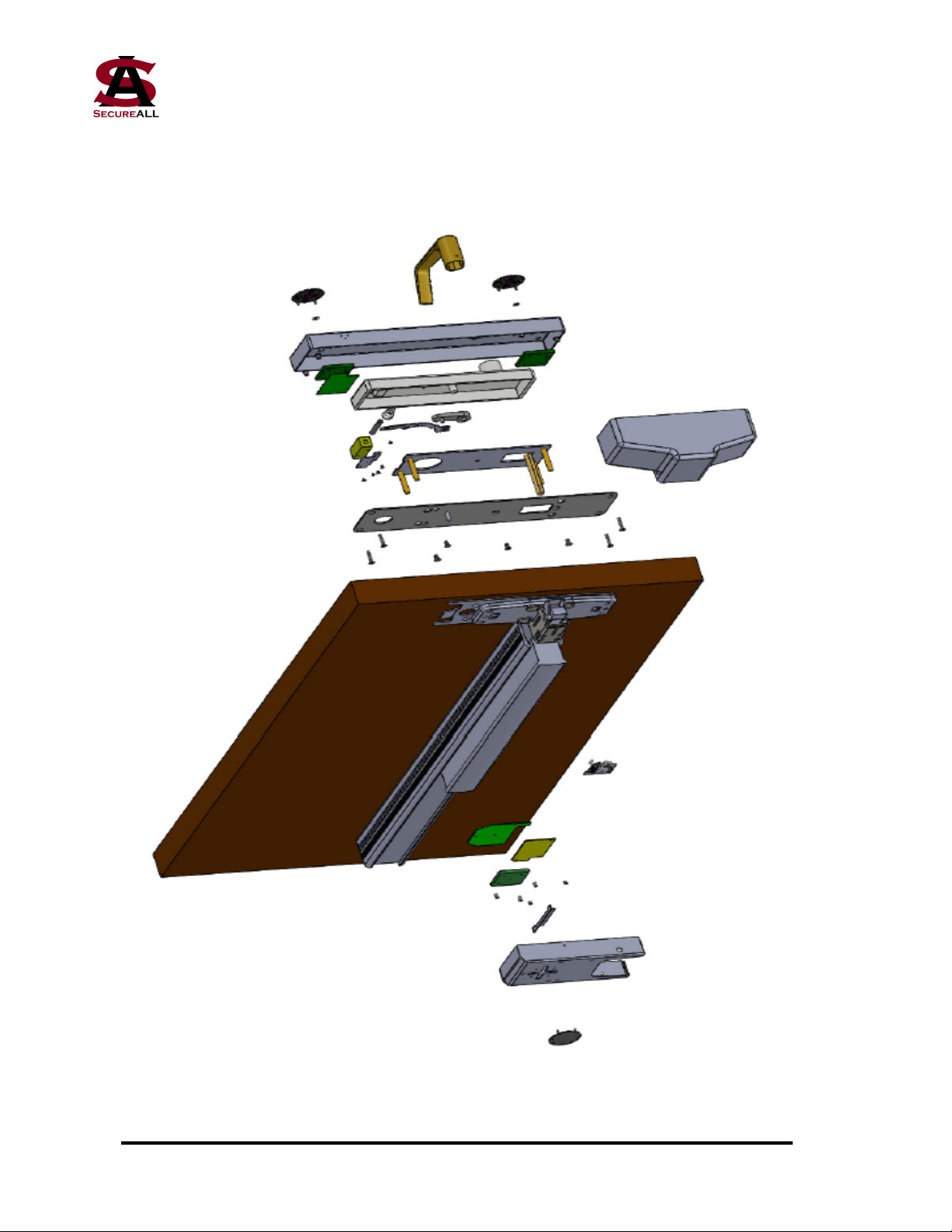
Appendix(A(-(Panic(Hardware(Reader,(Exploded(View...........................18(

Nnn-0000nn © Copyright 2017 SecureALL Corporation Page 4 of 18
Introduction
These instructions are intended to show you how to install a SecureALL Panic Hardware
Reader (SA-PHR) door assembly. This document assumes you have door hardware with a UL
Certified Von Duprin Series 98/99 fire-exit device. If you have any other door lock, contact
SecureALL for additional assistance. This installation guide applies to all door types requiring
3 hour fire rating.
Required Tools
1. Phillips screwdriver 6. Pliers
2. Power drill 7. Sensor tester
3. Dremel tool 8. Flashlight (optional)
4. Utility knife
5. M5 screw tap
Check the Materials
Verify you have the following materials needed for installation and that there is no damage to
anything from the packing, shipping, etc. If you find any damaged or missing items, contact
SecureALL immediately for assistance.
The following components are included with each door reader kit:
1. Back escutcheon unit
2. Front lock/antenna assembly
3. Microswitch sensor assembly and cabling
4. Metal pushbutton lockdown switch
5. Battery holder
6. Back mounting plate
7. Assorted screws and connectors
Installation Steps
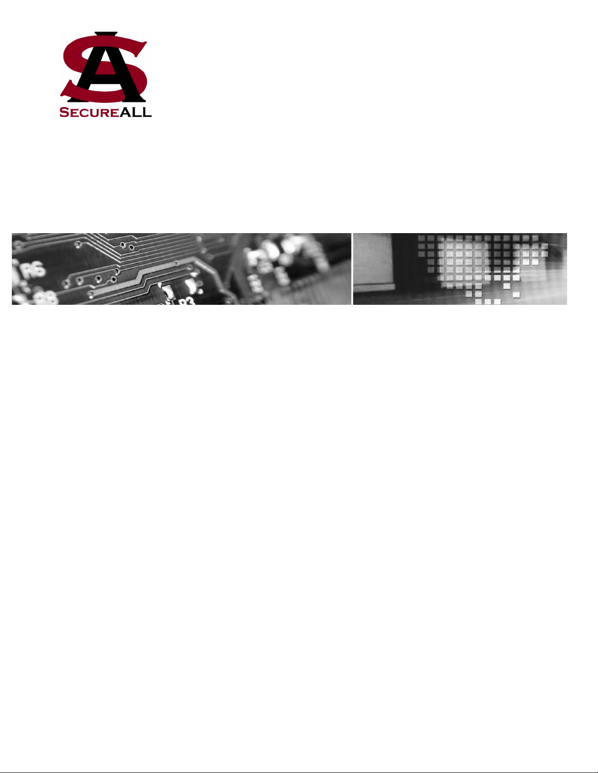
1. Remove the entire pushbar from inside the door. There are 3 screws in the endcap and
4 screws in the latch cover plate (Figures 1 and 2). After this is done, screws on the
inside of the pushbar unit attached to the door are removed to allow it to become free
(Figure 3). This will also allow the front lock to be removed (Figure 4).
Figure 1 Figure 2
Pushbar
screws
Pushbar
screws
Nnn-0000nn © Copyright 2017 SecureALL Corporation Page 5 of 18
Figure 3 Figure 4
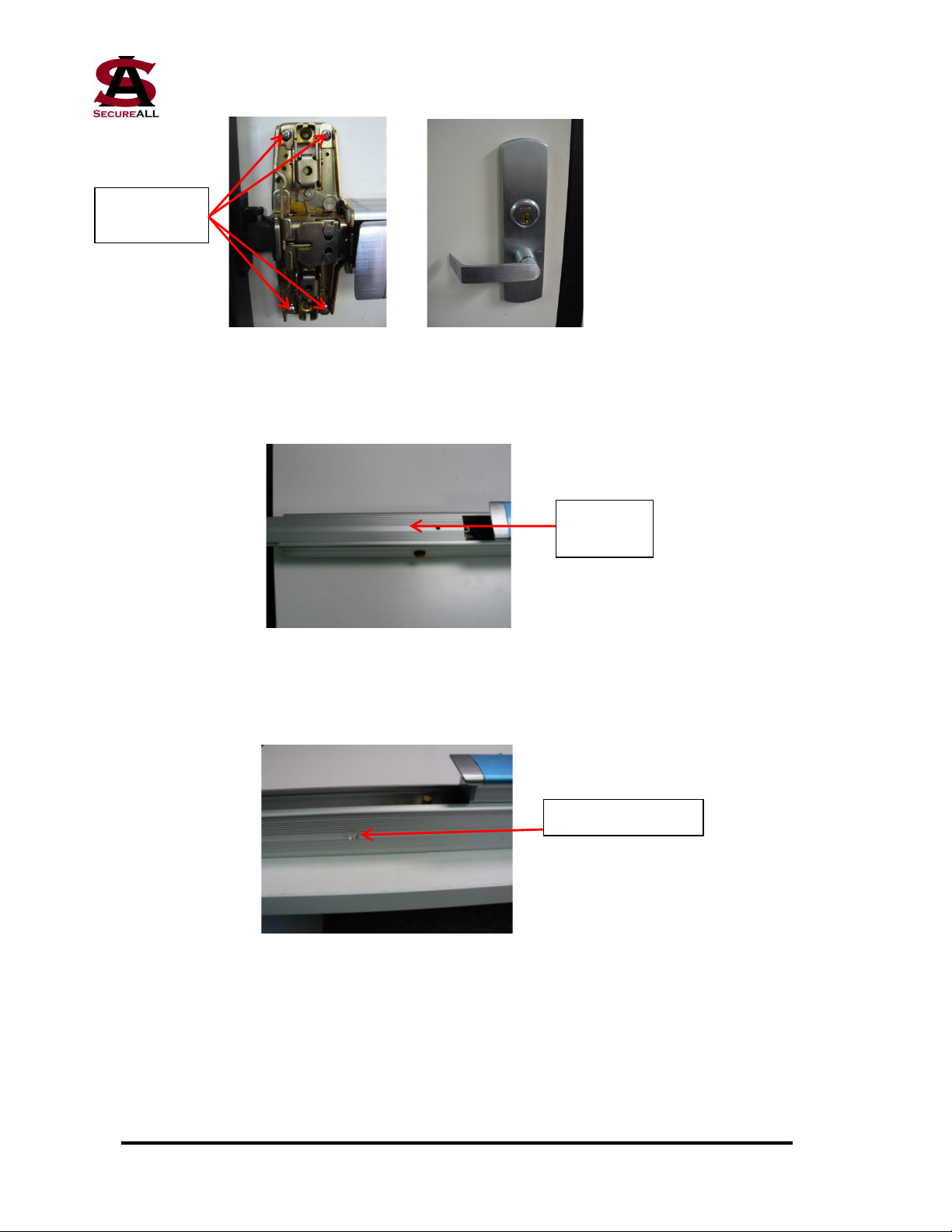
2. Slide the top rail of the pushbar unit away from the pushbar to expose the cavity area
(Figure 5).
Figure 5
3. Lay the pushbar unit on its side and drill a 5/8” hole in the middle of the underside,
(Figure 6).!
Figure 6
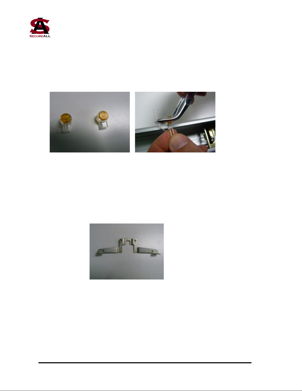
4. Take the Metal Pushbutton!Lockdown Switch (Figure 7) and remove the nut. Insert the
switch into the hole drilled in Step 3. Fasten it with the nut (Figure 8). !
!
!
!
!
Hole to drill, 5/8”
Pushbar
top rail
Remove
four screws
Nnn-0000nn © Copyright 2017 SecureALL Corporation Page 6 of 18
!!!! !
Figure 7 Figure 8
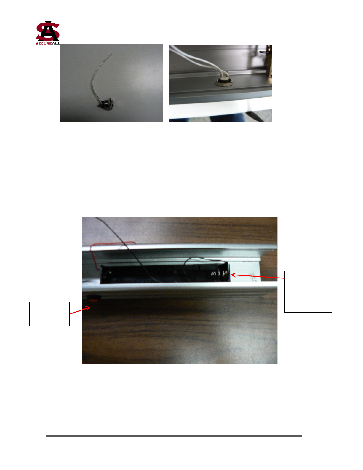
5. The battery box is installed next to the Lockdown Switch, with the spring toward the
open end of the pushbar unit (Figure 9). On the outside of the rail, vertically center the
battery box and use it as a template to mark locations of two screw holes (the battery
box has 4 holes in the corners; pick 2 holes in opposite corners). Drill pilot holes using
a #40 or #38 bit. Orient the battery box inside the rail, aligned with the pilot holes, and
attach using sheet metal screws supplied in the battery holder bag. Do not install the
batteries until the wires are connected (Step 14).
Figure 9
6. Remove the rail from the bottom of the pushbar unit as shown in Figure 10.
Lockdown
switch
Battery box
with spring
toward open
end
Nnn-0000nn © Copyright 2017 SecureALL Corporation Page 7 of 18
Figure 10
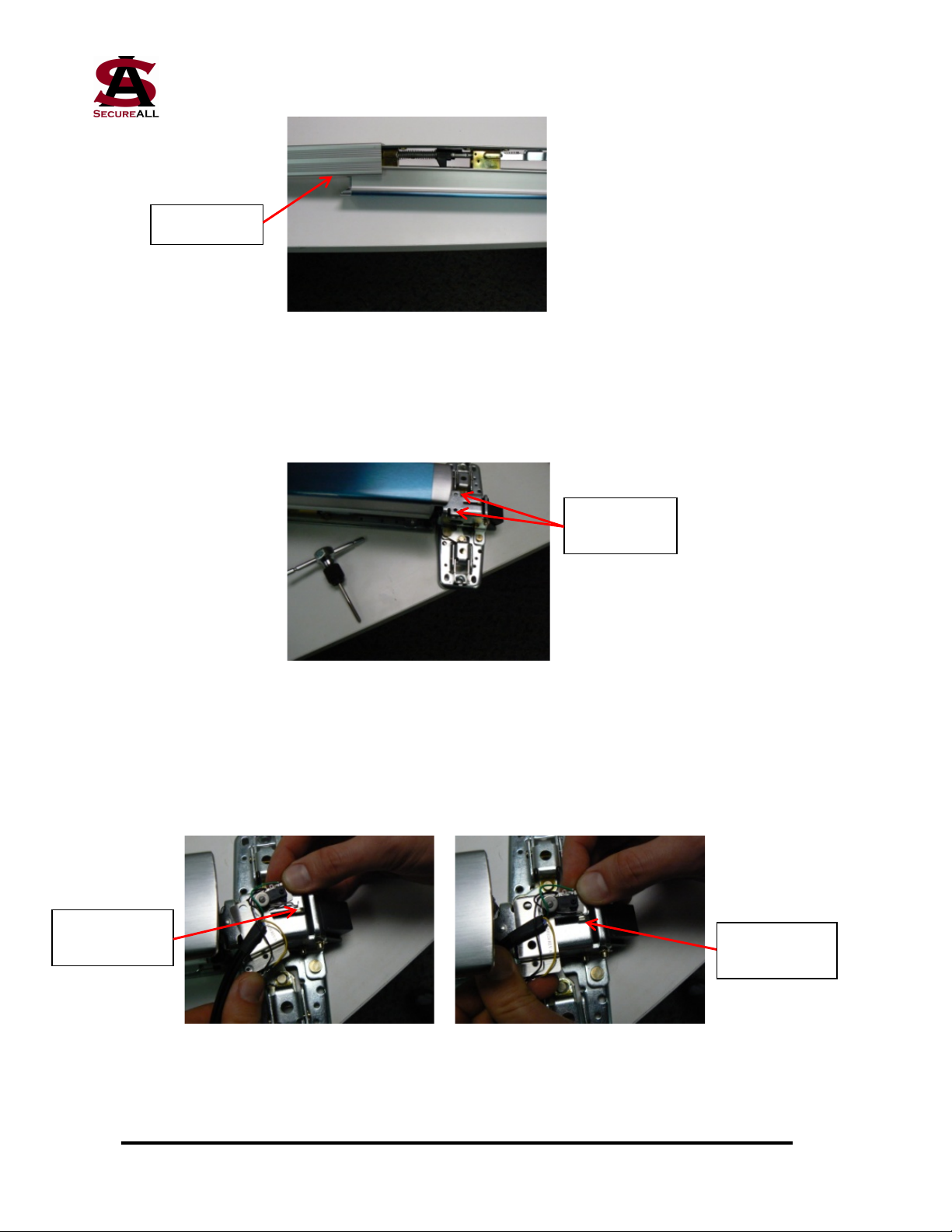
7. Turn the pushbar unit right side up, exposing the latching mechanism. There are two
holes at the top of the latch, right next to the pushbar. These need to be tapped using an
M5 screw tap (Figure 11).
Figure 11
8. A microswitch sensor assembly needs to be installed. Figure 12 shows the sensor
assembly being placed at an angle on top of the two tapped screw holes and then
rotated into place in Figure 13. This is required to ensure the microswitch is in the
closed position when the latch is extended.
Figure 12 Figure 13
Bottom rail
Holes to be
tapped
Microswitch
closed
Microswitch
open

Nnn-0000nn © Copyright 2017 SecureALL Corporation Page 8 of 18
9. Secure the microswitch with screws and lock washers. The top hole uses a screw, a
lock washer, and a regular washer (Figure 14). The bottom hole uses a clip to capture
the cable with flying leads, which is held in place with another screw and lock washer
(Figure 15).
Figure 14 Figure 15
10. The cable being held in place by the clip is routed along the side of the pushbar, just
behind the latch assembly (Figure 16), and then fed along the bottom of the pushbar
unit (Figure 17).
Figure 16 Figure 17
11. The end of the cable is fished under the bottom rail and pulled through until it reaches
the Lockdown Switch (Figures 18 and 19).
Figure 18 Figure 19
Cable clip
Cable routing
along bottom
of pushbar unit
Cable routing
behind latch
assembly
Nnn-0000nn © Copyright 2017 SecureALL Corporation Page 9 of 18
12. Hold the ends of the wires that are shown in Figure 19 and pull them lightly to tension
the cable while sliding the bottom rail back onto the pushbar unit. Make sure that the
cable remains seated in the channel between the rail and the pushbar unit.
13. The end of the cable and the Lockdown Switch are now connected using the fasteners
in Figure 20. Place one white wire from both the Switch and the cable into a fastener
and crimp it using a pair of pliers (Figure 21). Repeat for the second set of white wires.
Figure 20 Figure 21
14. The same procedure is carried out to connect the cable and the battery holder. Connect
the red battery wire to the red cable wire and the black battery wire to the black cable
wire. Install the batteries, being careful to ensure correct polarity (negative at the
spring connection).
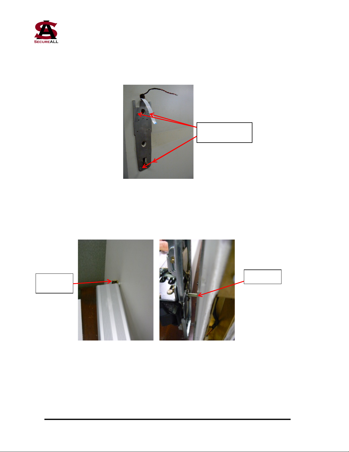
15. Install the first mounting bracket that is used to attach the pushbar unit to the door
(Figure 22).
Figure 22
16. Place the bracket as shown in Figure 23 and secure with screws per Figure 24.

Nnn-0000nn © Copyright 2017 SecureALL Corporation Page 10 of 18
Figure 23 Figure 24
17. Take the cable in the sensor assembly with the connector and fish it through the bottom
of the bracket installed in Step 16 (Figure 25). The cable should always come out on the
top side when mounted on the door. Use a tie-wrap to secure the cable and the bracket.
Figure 25
18. Test the functionality of the latch sensors and the Lockdown Switch. Place the cable
from Step 17 into the sensor tester as shown in Figure 26. The LED on the left hand
side of the board will light. As the lever, deadlatch and Lockdown Switch are
depressed, a different LED will light on the right hand side of the board. If any of the
LEDs does not light, check to make sure all connections are in place. If everything is
as designed, replace the sensor cable.
Figure 26
Cable routing
through the
mounting bracket
LEDs light as lever,
deadlatch and
pushbutton switch are
depressed

Nnn-0000nn © Copyright 2017 SecureALL Corporation Page 11 of 18
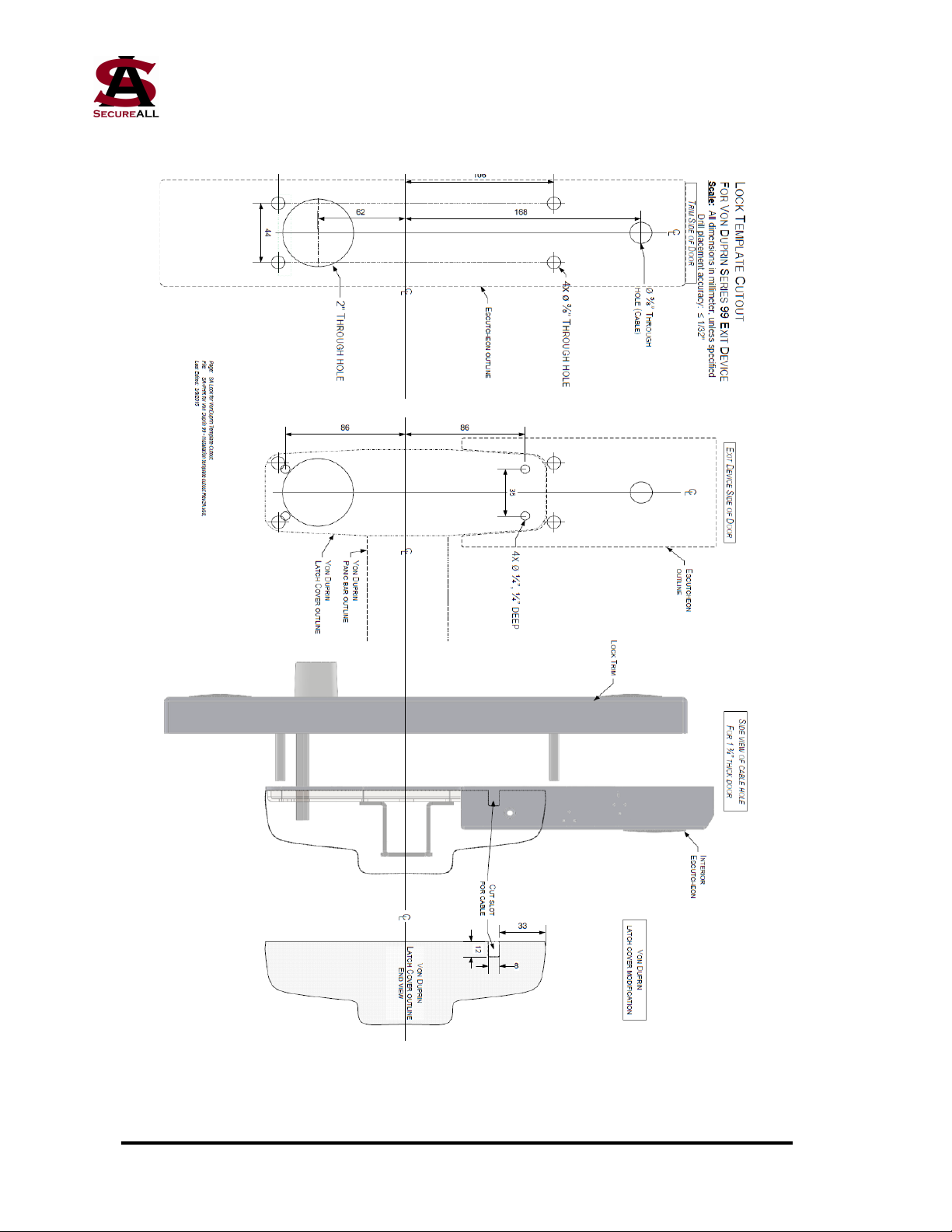
19. The hole pattern in the door that mounts the exit unit must be modified slightly to
accept the SecureALL hardware. Use an electric drill or Dremel tool to modify the
holes per the supplied template (See Appendix A).
20. SecureALL supplies the "front lock/antenna assembly" (Figure 27, outside view; Figure
28, inside view).
Figure 27 Figure 28
21. Take the cables that are extending from the front lock/antenna assembly and feed it
through the central hole in the uppermost set of holes on the door (Figure 29). Push the
four metal posts into the top and bottom holes in the door until the unit is flush against
the door (Figure 30). Make sure the cable is fully extended and not caught between the
front lock/antenna assembly and the door.
Figure 29 Figure 30
Nnn-0000nn © Copyright 2017 SecureALL Corporation Page 12 of 18
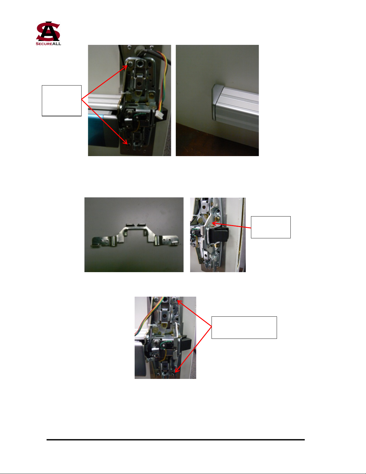
22. Mount the back mounting plate (Figure 31). Attach with four screws. For improved
fire safety, a fire barrier caulk, such as 3M's CP 25WB+, can be injected into the large
upper hole.
Figure 31
23. Remount the pushbar unit on the door. Slide the non-latch side into the mounting
bracket at the far end (Figure 32) and push the latch side onto the spindle that extends
from the back mounting plate (Figure 33).
Figure 32 Figure 33
24. Screw the lever end of the pushbar unit to the door as shown in Figure 34 and tighten
the screws that attach the rear bracket to the door. Replace the endcap over the rear
bracket (Figure 35).
Spindle
Rear
bracket
Attach back
mounting plate
Nnn-0000nn © Copyright 2017 SecureALL Corporation Page 13 of 18
Figure 34 Figure 35
25. Insert the second (outside) mounting bracket (Figure 36) into the lever end of the
pushbar (Figure 37) and screw to the door (Figure 38).
Figure 36 Figure 37
Figure 38
26. Using the Dremel tool, cut a small slot in the metal cover that goes over the lever
portion of the pushbar. The slot is located on the inside, top portion of the cover
(Figure 39). The slot should be only be as large as the sensor cable diameter.
Connect
pushbar to
door
Mounting
bracket
Screws mounting
bracket to door

Nnn-0000nn © Copyright 2017 SecureALL Corporation Page 14 of 18
Figure 39
27. Slide the metal cover in Figure 39 over the lever portion of the pushbar, feeding the
sensor cable that extends from under the first mounting bracket through the slot (Figure
40). Note that this cable contains connectors for both the deadlatch sensor and the
battery holder.
Figure 40
28. Screw the metal cover plate onto the lever portion of the pushbar using just the two
screws at the bottom (Figure 41). Use the short thread-cutting screws that came with
the pushbar unit.
Figure 41
Sensor & battery
cable
Attach with inside
and outside screws
at bottom
Slot for sensor
& battery cable

Nnn-0000nn © Copyright 2017 SecureALL Corporation Page 15 of 18
29. The back escutcheon unit has a printed circuit board mounted in it (Figure 42). The
sockets on the board are a) front electronic connection (flat cable), b) solenoid, c)
sensors and d) battery. Take the two cables that extend through the door and connect
them to the two lower sockets, running both cables above the metal mounting bracket.
Take the sensor/battery cable from the slot cut in the cover plate, run it below the metal
mounting bracket and then connect the two leads to the two upper sockets. Always
remember to connect the battery cable last. Observe the LED. It should come on solid
red for approximately one second and then go out. If it stays on for more than that
time, unplug all the cables and repeat this section. IMPORTANT CAUTION: This
unit should never run hot. If it feels warm to the touch, immediately remove all the
cables and repeat this section. If the problem reoccurs, set the unit aside for analysis.
Figure 42
30. Complete installation by sliding the metal mounting bracket on the back escutcheon
unit onto the metal mounting plate, making sure that the cables are not pinched. Put the
two long thread-cutting screws (supplied by SecureALL) into the top holes of the metal
cover (Figures 43 and 44).
Flat cable
Battery
Solenoid
Sensors
Metal
mounting
bracket

Nnn-0000nn © Copyright 2017 SecureALL Corporation Page 16 of 18
Figure 43 Figure 44
Nnn-0000nn © Copyright 2017 SecureALL Corporation Page 17 of 18
APPENDIX A - INSTALLATION TEMPLATE
Nnn-0000nn © Copyright 2017 SecureALL Corporation Page 18 of 18
APPENDIX B - PANIC HARDWARE READER, EXPLODED VIEW
Table of contents
Popular Door Lock manuals by other brands

Assa Abloy
Assa Abloy Corbin Russwin Access 600 CL33600 TCRNE1... installation instructions

Hafele
Hafele DT 100 FH installation instructions

TownSteel
TownSteel XTRX-L-2000 Programming guide

Water Street Brass
Water Street Brass 41035 quick start guide

Assa Abloy
Assa Abloy SARGENT 2828 Series instructions

Hoppe
Hoppe ConnectSense Installation & user manual


