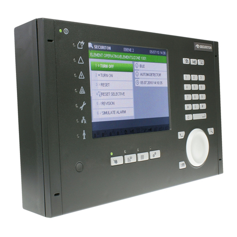
Securiton SecuriFire 1000 User manual

Securiton AG Alpenstrasse 20 3052 Zollikofen Switzerland T 811 086 en e
SecuriFire 1000/2000
Mounting and installation
Technical Description


Imprint
Mounting and installation, Technical Description, T 811 086 en e 3 / 128
Imprint
Notice
This document, T 811 086, is valid only for the product described in Section 1.
This document is subject to change or withdrawal without prior notice. The validity of the statements made in
this document applies until the statements are revised by a new edition of the document (T number with new in-
dex). The user of this document is responsible for staying up to date with its current status through the edi-
tor/publisher. We accept no responsibility for claims against any incorrect statements in this document which
were unknown to the publisher at the time of publication. Handwritten changes and additions are not valid. This
document is protected by copyright.
Foreign language documentation as listed in this document is always released or changed at the same time as
the German edition. If there are inconsistencies between the foreign language documentation and the German
documentation, the German documentation is binding.
Some words in this document are highlighted in blue. These are terms and designations which are the same in
all languages and are not translated.
Users are encouraged to contact the editor/publisher if there are statements which are unintelligible, misleading,
incorrect, or if there are errors.
© Securiton AG, Alpenstrasse 20, 3052 Zollikofen, Switzerland
This document, T 811 086
1
, is available in the following languages: German T 811 086 de
English T 811 086 en
French T 811 086 fr
Italian T 811 086 it
Swedish T 811 086 sv
Current edition: Index e 07.04.2015 Rd
1
Reference document: CX-Handbuch V1.1, MMI&EPI Handbuch V2.1, LAN-Handbuch, X-Line Handbuch

Safety information
4 / 128 Mounting and installation, Technical Description, T 811 086 en e
Safety information
Provided the product is deployed by trained and qualified persons in accordance with technical document T 811 086 and the
danger, safety and general information notices in this technical documentation are observed, there is no danger to persons
or property under normal conditions and when used properly.
National and state-specific laws, regulations and guidelines must be observed and adhered to in all cases.
Below are the designations, descriptions and symbols of danger, safety and general information notices as found in this
document.
Danger
If the Danger notice is not properly observed, the product and other system parts may present a hazard for per-
sons and property, or the product and other system parts may be damaged to the extent that malfunctioning re-
sults in danger to persons and property.
Description of which dangers can occur
Measures and preventative actions
How dangers can be averted
Other safety-relevant information
Warning
The product may be damaged if the safety information is not heeded.
Description of which damage can occur
Measures and preventative actions
How dangers can be averted
Other safety-relevant information
Notice
The product may malfunction if this notice is not observed.
Description of which malfunctions can be expected
Measures and preventative actions
Other safety-relevant information
Environmental protection / recycling
Neither the product nor product components present a hazard to the environment provided they are handled
properly.
Description of which parts have environmental protection issues
Description of how devices and their parts have to be disposed of in an environmentally-friendly way
Description of the recycling possibilities
Batteries
It is not permitted to dispose of batteries in the domestic rubbish. As the end user you are legally obliged to re-
turn used batteries. Used batteries can be returned free of charge to the seller or brought to a designated recy-
cling point (e.g. to a communal collection point or retailer). You may also send them back to the seller by post.
The seller refunds the postage when you return your old batteries.

Document history
Mounting and installation, Technical Description, T 811 086 en e 5 / 128
Document history
First edition Date 01.07.2011
Index „a“ Date 01.10.2011
Most important changes compared with first edition:
Section
New (n) / changed (c) / deleted (d)
What / Reason
1.3
c
Overview of system limits
Table adjusted
1.4
n
Overview of SecuriLine eXtended limits
New notice
2.3, Fig. 2
n
B6-ADB 10
New product
0
n
Dimensions for external indication and control maps
New EHB 701
3.3, Fig. 24, 3.4,
Fig. 25, Fig. 26
n
Surface mounting and flush mounting
New section
10.3.6, Fig. 136
n
BX-O2I4 connection
New section
Fig. 73
c
SecuriFire VirtualMIC connection
New section
6.22
d
ComBOX connection
Sentence removed and not replaced
9.4, Fig. 109,
Fig. 110, Fig. 111,
Fig. 112
n
MIC711
New section
9.5.3
n
Overview of RS485 PIN assignments
New section
9.5.5
c
SecuriLan connection
Text adaptations
Index „b” Date 13.02.2012
Most important changes compared with previous edition:
Section
New (n) / changed (c) / deleted (d)
What / Reason
1.4
c
Overview of SecuriLine eXtended limits
„BX-SOL, BX-SBL per loop“ changed
Fig. 37
c
B6-BCB, connection of inputs
For „unmonitored inputs“ bridge re-
moved
Fig. 122
c
Connecting SecuriLine eXtended
Product name changed
Fig. 123
c
Stub line connection
Change
Index „c” Date 14.05.2013
Most important changes compared with previous edition:
Section
New (n) / changed (c) / deleted (d)
What / Reason
all
c
Languages de, en, fr, it: Document number
previously T131470, new T811086
Administrative
10.3.4
c
Connection of BX-AIM advanced input module
Text adjusted
10.3.5
c
BX-OI3 output/input module connection
Text adjusted
10.3.10
c
BX-IOM input/output module connection
Text adjusted
10.3.11
c
BX-IM4 input module connection
Text adjusted
10.3.12
c
BX-RGW radio module connection
Text adjusted
10.3.15
c
Connection of end switch module eXtended Line
BX-ESL
Text adjusted
7.4
c
B5-MMI-FIP floor panel
Text adjusted
8.4
c
B5-EPI-FPC-GS Swiss fire brigade panel
Text adjusted
9.1
c
B6-NET2-485 network unit
Text adjusted
9.2
c
B6-NET2-FXM and B6-NET2-FXS network units
Text adjusted
9.3
c
B6-LAN interface unit
Text adjusted
9.4
c
MIC711
Text adjusted
9.5
c
SecuriLan connection
Text adjusted
9.5.6
c
SecuriLan connection with fibre optics
Text adjusted

Document history
6 / 128 Mounting and installation, Technical Description, T 811 086 en e
Index „d” Date 15.01.2014
Most important changes compared with previous edition:
Section
New (n) / changed (c) / deleted (d)
What / Reason
general
n
Update to SecuriFire release R 2.0
Actualisation
10.3.6
n
BX-I2 input module connection
New section
10.3.7
n
BX-O1 output module connection
New section
10.3.16
n
Connection for SDI81X / SDI82X addressing mod-
ule
New section
6.1
n
B6-LXI2 SecuriLine unit
New section
6.3
n
B6-EIO input/output unit
New section
6.13
n
MMD130 Ex-i in Ex-areas with safety barrier Z787
New section
6.14
n
MMD130 Ex-i in Ex-areas with direct current isolat-
ing transformer GTW 01
New section
6.23.2
c
External parallel printer on RS422 interface with
converter
Text and graphic adjusted
7.4
n
B5-MMI-FIP
New section
7.5
n
B5-MMI-FPS-S Fire brigade panel Sweden
New section
8.5
n
B5-EPI-ASP-GS alarm scrolling panel for the
Netherlands
New section
8.6
n
B5-EPI-FPS-S fire brigade operating panel for
Sweden
New section
8.7
n
B5-EPI-PCM partial indication and control map
New section
8.8
n
B5-EPI-PIM partial indication map
New section
Index „e” Date 07.04.2015
Most important changes compared with previous edition:
Section
New (n) / changed (c) / deleted (d)
What / Reason
general
n
Update to SecuriFire release R 2.0
Actualisation

Contents
Mounting and installation, Technical Description, T 811 086 en e 7 / 128
Contents
_________________________________________________________________________________________
1System overview 13
1.1 Technical data 15
1.2 Overview of control panels 15
1.3 Overview of system limits 16
1.4 Overview of SecuriLine eXtended limits 16
_________________________________________________________________________________________
2SecuriFire 1000/2000 control panels 17
2.1 Map case design and dimensions 17
2.2 Basic design 17
2.3 B6-ADB 10 additional box 18
2.4 B6-MIC11 built-in control panel 18
2.5 Mounting a control panel 18
_________________________________________________________________________________________
3External main indication and control maps 19
3.1 Dimensions for external indication and control maps (all dimensions in mm) 19
3.2 Drilling plans for external indication and control maps 20
3.3 MIC711 surface mounting with plan box 21
3.4 Flush mounting 21
_________________________________________________________________________________________
4Power supply 22
4.1 Emergency power supply (batteries) 22
4.2 Mains and battery connection 22
4.3 B6-PSU power supply unit 23
4.3.1 Interfaces 23
4.3.2 Technical data 23
4.3.3 Compatibility information 23
4.3.4 Connection of external consumers 24
4.3.5 Battery current measurement 24
_________________________________________________________________________________________
5Main control units 25
5.1 B6-BCB12 main control unit SecuriFire 1000 25
5.1.1 Interfaces 25
5.1.2 Technical data 26
5.1.3 Compatibility information 26
5.2 SecuriFire 2000 B6-BCB13 main control unit 27
5.2.1 Interfaces 27
5.2.2 Technical data 28
5.2.3 Compatibility information 28
5.3 Connection of monitored inputs and outputs 29
5.3.1 Technical data 29
5.3.2 Connection of monitored outputs to B6-BCB 30
5.3.3 Connection of inputs to B6-BCB 31
5.3.4 Connection of relay outputs to B6-BCB 31
5.3.5 Technical data 31
5.3.6 Connection examples 32
5.3.7 “Extinguishing” standard interface connection compliant with VdS 33
5.3.8 “Fault” standard interface connection compliant with VdS 34
5.3.9 Fire brigade map connection to B6-BCB compliant with DIN 14661 35
5.3.10 SecuriLine eXtended 36
5.3.11 Connector plug for SecuriLine eXtended 36
5.3.12 Technical data 36
5.3.13 Compatibility information 37

Contents
8 / 128 Mounting and installation, Technical Description, T 811 086 en e
_________________________________________________________________________________________
6Expansion units for SecuriFire 2000 38
6.1 B6-LXI2 SecuriLine unit 38
6.1.1 Interfaces 38
6.1.2 Technical data 38
6.1.3 Compatibility information 38
6.2 B4-DAI2 SecuriLine unit 39
6.2.1 Interfaces 39
6.2.2 Technical data 39
6.2.3 Compatibility information 39
6.3 B6-EIO input/output unit 40
6.3.1 Interfaces 40
6.4 Connector plugs for detection zones and inputs (X2, X3) 40
6.5 Connector plug for monitored outputs (X4) 42
6.5.1 Connection assignment for plug (X4) 42
6.6 B4-EIO input/output unit 43
6.6.1 Interfaces 43
6.7 Connector plugs for detection zones and inputs (X2, X3) 43
6.8 Connector plug for monitored outputs (X4) 45
6.8.1 Connection assignment for plug (X4) 45
6.9 Connecting the detector series SecuriStar 521 / 523 / 563 and MCP 521, 525 46
6.9.1 Connecting detector base USB 501 46
6.9.2 Connecting MCP 521N manual call points 46
6.9.3 Connecting MCP 525 manual call points 46
6.10 Connecting detector base 143 and 143K 46
6.11 Detector base 143 Ex-i with safety barrier Z787 47
6.12 Detector base 143 Ex-i with direct current isolating transformer GTW 01 47
6.13 MMD130 Ex-i in Ex-areas with safety barrier Z787 48
6.14 MMD130 Ex-i in Ex-areas with direct current isolating transformer GTW 01 48
6.15 Connecting Hochiki Ex-i detectors in Ex areas 49
6.16 Connecting monitored inputs 50
6.16.1 Monitored input 26k7 50
6.16.2 Monitored input 3k 50
6.17 Connecting extinguishing inputs 51
6.17.1 Valve monitoring 51
6.17.2 Extinguishing input in accordance with VdS 51
6.18 Connection of monitored outputs 51
6.18.1 Technical data 52
6.18.2 Compatibility information 52
6.19 B4-USI universal interface unit 53
6.19.1 Interfaces 53
6.19.2 Technical data 53
6.19.3 Compatibility information 54
6.19.4 Plug assignment with screened cabling 54
6.19.5 Plug assignment with unscreened cabling 55
6.20 Connection to management and third-party systems (non-redundant) 56
6.20.1 Connecting management system / ESPA to RS232 interface 56
6.20.2 Connecting management system /ESPA via converter 56
6.21 Connection to management and third-party systems (redundant) 57
6.21.1 Connection to an interface-redundant management system via RS422 57
6.22 ComBOX connection 58
6.22.1 Serial connection of the ComBOX to B4-USI 58
6.22.2 Serial connection of the ComBOX via ADAM 4520 58
6.22.3 Connection of the ComBOX to SecuriFire via contacts 59
6.23 External printer connection 60
6.23.1 External printer to RS232 interface 60
6.23.2 External parallel printer on RS422 interface with converter 60

Contents
Mounting and installation, Technical Description, T 811 086 en e 9 / 128
_________________________________________________________________________________________
7MMI-BUS devices 61
7.1 MMI-BUS schematic drawing 61
7.2 MMI-BUS technical data 61
7.3 Connection of MMI-BUS participants 62
7.3.1 Jumper assignment for MMI-BUS termination 62
7.3.2 MMI-BUS connection open 62
7.3.3 MMI-BUS connection terminated 63
7.3.4 MMI-BUS connection with star-shaped power supply 64
7.4 B5-MMI-FIP floor panel 65
7.4.1 Interfaces 65
7.4.1.1 MMI bus power supply connector plug (X1) and power supply (X2) 65
7.4.2 Instructions for opening and mounting the B5-MMI-FIP 66
7.4.3 Technical data 66
7.4.4 Compatibility information 66
7.5 B5-MMI-FPS-S Fire brigade panel Sweden 67
7.5.1 Interfaces 67
7.5.1.1 MMI bus power supply connector plug (X1) and power supply (X2) 67
7.5.2 Instructions for opening and mounting the B5-MMI-FPS-S 68
7.5.3 Technical data 68
7.5.4 Compatibility information 68
7.6 B3-MMI-UIO universal input/output module 69
7.6.1 Interfaces 69
7.6.2 MMI bus power supply connector plug (X1) and power supply (X2) 69
7.6.3 Technical data 71
7.6.4 Compatibility information 71
7.7 B3-MMI-FAT fire brigade indicator board 72
7.7.1 Interfaces 72
7.7.2 Technical data 73
7.7.3 Compatibility information 73
7.8 B5-MMI-FPCZ Fire brigade panel Czechia 74
7.8.1 Interfaces 74
7.8.2 Technical data 74
7.8.3 Compatibility information 74

Contents
10 / 128 Mounting and installation, Technical Description, T 811 086 en e
_________________________________________________________________________________________
8EPI-BUS devices 75
8.1 Schematic of an EPI bus 75
8.2 EPI bus features 75
8.3 Connection of EPI bus participants 75
8.4 B5-EPI-FPC-GS Swiss fire brigade panel 76
8.4.1 Interfaces 76
8.4.2 Technical data 76
8.4.3 Compatibility information 76
8.5 B5-EPI-ASP-GS alarm scrolling panel for the Netherlands 77
8.5.1 Interfaces 77
8.5.2 Technical data 77
8.5.3 Compatibility information 77
8.6 B5-EPI-FPS-S fire brigade operating panel for Sweden 78
8.6.1 Interfaces 78
8.6.2 Technical data 78
8.6.3 Compatibility information 78
8.6.4 Instructions for opening and mounting the B5-EPI-FPS-S 79
8.7 B5-EPI-PCM partial indication and control map 80
8.7.1 Interfaces 80
8.7.2 Technical data 80
8.7.3 Compatibility information 80
8.8 B5-EPI-PIM partial indication map 81
8.8.1 Interfaces 81
8.8.2 Technical data 81
8.8.3 Compatibility information 81
8.9 B5-EPI-FAT fire brigade indicator board 82
8.9.1 Interfaces 82
8.9.2 Technical data 82
8.9.3 Compatibility information 82
8.10 B5-EPI-FPD fire brigade control panel 83
8.10.1 Interfaces 83
8.10.2 Technical data 83
8.10.3 Compatibility information 83
_________________________________________________________________________________________
9SecuriLan network units and MIC711 84
9.1 B6-NET2-485 network unit 84
9.1.1 Interfaces 84
9.1.2 Technical data 84
9.1.3 Compatibility information 84
9.2 B6-NET2-FXM and B6-NET2-FXS network units 85
9.2.1 Interfaces 85
9.2.2 Technical data 86
9.2.3 Compatibility information 86
9.3 B6-LAN interface unit 87
9.3.1 Interfaces 87
9.3.2 Technical data 87
9.3.3 Compatibility information 87
9.4 MIC711 88
9.4.1.1 Power supply connection plug (X1) 89
9.4.1.2 RS485 plug network connection (X4) 89
9.4.2 Technical data 89
9.5 SecuriLan connection 90
9.5.1 Connection types 90
9.5.2 SecuriLan connection with RS485 interfaces 91
9.5.3 Overview of the PIN assignments of all SecuriLan participants 92
9.5.4 SecuriLan connection with 10/100TX interface 93
9.5.5 SecuriLan connection via Ethernet network (logical connection) 93
9.5.6 SecuriLan connection with fibre optics 94
9.5.7 Example of connecting a SecuriLan 95
9.6 SecuriFire VirtualMIC connection 96
9.6.1 Local SecuriFire VirtualMIC connection 96
9.6.2 SecuriFire VirtualMIC connection via switch 97
9.6.3 SecuriFire VirtualMIC access via intranet/internet 97

Contents
Mounting and installation, Technical Description, T 811 086 en e 11 / 128
_________________________________________________________________________________________
10 SecuriLine eXtended 98
10.1 General 98
10.2 Max. number of participants per line interface and mode of operation 99
10.3 Connection of SecuriLine eXtended modules 100
10.3.1 Stub line connection 101
10.3.2 Connecting detector base USB 501 101
10.3.3 Connection of MCP 535x and MCP 545x manual call points 102
10.3.4 Connection of BX-AIM advanced input module 102
10.3.5 BX-OI3 output/input module connection 103
10.3.6 BX-I2 input module connection 104
10.3.7 BX-O1 output module connection 105
10.3.8 BX-O2I4 output / input module connection 105
10.3.9 BX-REL4 relay module connection 106
10.3.10 BX-IOM input/output module connection 106
10.3.11 BX-IM4 input module connection 107
10.3.12 BX-RGW radio module connection 107
10.3.13 Connection of the BX-SOL loop siren 108
10.3.14 Loop flashlight BX-FOL connection 108
10.3.15 Connection of end switch module eXtended Line BX-ESL 109
10.3.16 Connection for SDI81X / SDI82X addressing module 109
10.4 Connection for BX-MDH door holding magnet 110
10.5 Connection for BX-MDI8 input module 110
_________________________________________________________________________________________
11 Programming and software 114
_________________________________________________________________________________________
12 Annex 115
12.1 Recommended cable types 115
12.1.1 Data cable for SecuriLan, unscreened 115
12.1.2 Data cable for MMI-BUS, unscreened 115
12.1.3 Data cable for MMI-BUS, screened 115
12.1.4 Screened addressable loop cable 115
12.1.5 Power supply for MMI-BUS 116
12.2 SecuriLan cable specification 117
12.3 Crimping the RJ-45 plug 118
12.4 Power requirement calculation 121
12.5 Connection of FSS 800-1 fire brigade key box 122
12.6 Protocol printer 123
12.6.1 Changing printer paper 123
12.6.2 Replacing ink ribbon 123
12.7 Simple troubleshooting 124
12.7.1 General 124
12.7.2 Contaminated detector 124
12.7.3 Possible causes of faults 124
_________________________________________________________________________________________
13 Article numbers / spare parts 124
_________________________________________________________________________________________
14 List of figures 125


System overview
Mounting and installation, Technical Description, T 811 086 en e 13 / 128
1 System overview
SecuriFire 1000
The SecuriFire 1000 system is a non-modular fire alarm control panel for small scale systems. A maximum of 250 elements
can be connected to the addressable loop. The SecuriFire 1000 cannot be integrated into a SecuriLan and is not network ca-
pable.
SecuriFire 2000
The SecuriFire 2000 system is a fire alarm control panel for mid to small scale systems. A maximum of 500 elements can be
connected to the two addressable loops. It also has an interface to which either 2 additional addressable loops or interface
units can be connected (for integration in SecuriLan, networks, for connecting to management systems, etc.).
For further information about SecuriFire 1000/2000 fire detection systems, please refer to the document “SecuriFire system
description”, T 811 024.
Control panel and SecuriLan
The fire alarm control panel consists of 1 to 16 control panels (SCPs) which can be distributed in the building as needed.
Straightforward operation is provided from one location. Despite its decentral design, from outside the system it appears to
behave as if it were a “central” fire alarm control panel. When several SCPs are joined to a fire alarm system it is called a
“SecuriLan”.
External indication and control maps and BUS devices
The external SecuriFire MIC711 main indication and control map is connected directly to the SecuriLan.
Every SecuriFire MIC and some MMI devices have an EPI bus interface. Up to 3 non-redundant indication and control maps
can be connected to this data bus. They can be mounted up to 1 m from the interface. This means that the additional main
indication and control maps must be integrated into the map case of the control unit or positioned directly next to or near the
MIC711.
External indication and control maps and other devices are connected to the indication and control map via the MMI -BUS.
Up to 15 participants can be connected to this serial bus and they can be up to 1,200 m from the control unit. Repeaters are
not required. Data communication is by means of redundant, digital communication lines. The devices can be freely com-
bined with each other and are not restricted to location. For normative and security reasons, the data line and power supply
are redundantly implemented, whereby they are separately conveyed.
Line lengths
The maximum distance between two SecuriFire participants can be up to 1,200 m. Neither repeaters nor other devices such
as modems are necessary. Only the cable type and ambient conditions must be taken into consideration. If the distance has
to be more than 1,200 m, fibre-optic connections must be implemented.
Overvoltage protection
The SecuriFire 1000/2000 system is equipped with a comprehensive and integrated overvoltage protection design which pro-
tects all peripheral inputs including the mains power supply in compliance with EN 50130-4 (EMC) and EN -61000-6-2 (Im-
munity for industrial environments). The EMC protection design protects the electronics by means of a zone concept, Tran-
szorp diodes, filters and broadband decoupling of the power supply. Thus, when the system is used in buildings with in-
stalled basic and medium protection (lightning protection, mains overvoltage arresters), no further measures (e.g. overvolt-
age arresters) are required.

System overview
14 / 128 Mounting and installation, Technical Description, T 811 086 en e
Earthing concept
The earthing concept used in the SecuriFire 1000/2000 with central protection earthing to protect persons and electronics re-
quires that all electrically charged components connected to the GND line of the SecuriFire 1000/2000 control panel may be
installed only in areas and buildings which have regulation-complaint potential equalization.
Warning
Non-observance can cause malfunctions and/or damage the control panel and may endanger people.
Software
The SecuriFire 1000/2000 microprocessor-controlled system is equipped with a multitasking-capable, real-time operating
system. A basic function program is loaded into the system and is adjusted to the object to be protected by means of cus-
tomer-specific programming while taking into consideration relevant applicable standards.
Notice
This document applies to SRP 2.0 (SecuriFire Release Package) and later.
It is always recommended to use the most recent SecuriFire Studio release.
Important features
Microprocessor-controlled and monitored system technology.
Continual, automatic check routines for all system components and programs.
Units connected easily with blade connector.
Up to 31 external main indication and control maps per SecuriLan with graphic display; up to 4 languages can be toggled
during operation.
Integrated protocol printer with emergency power supply and event memory with message filter.
Suitable for connection to the public alarm system of the fire brigade.
Can be connected to superordinate computer systems and fire alarm deployment management systems via a serial inter-
face protocol with full functional scope (alarm/command directions).
Fully redundant interconnection of up to 16 control panels without superordinate central computer.
Superordinate networking of nearly any number of fire alarm control panels (also subsequently).
A maximum of 250 participants per loop and loop length of up to 3,500 m.
Main indication and control maps, protocol printers, parallel indicator boards and other system components are con-
nected by digital communication lines and can be deployed in any combination irrespective of location with any control
panel.
This complies with the following standards and directives: European standards EN 54, DIN, ÖNORM, ÖVE and VDE.
VdS devices and system approval (G209049, S209049, G209047, G209048, S209047).

System overview
Mounting and installation, Technical Description, T 811 086 en e 15 / 128
1.1 Technical data
Mains voltage:
230 V AC
Operating voltage:
typically 27 V depending on the ambient temperature and charge state
Usable batteries:
2 pcs. 12 V / 15...17 Ah in series
Emergency current supply with batteries:
according to current calculation
Alarm current:
max. 3.5 A
Ambient temperature:
-5°C to +50°C, measured at natural convection
Heat output performance:
typically <10 W
max. 20 W (at full load)
Colour:
grey RAL 7035
Relative air humidity:
5% to 95%, without condensation
Air pressure:
<= 80 kPa, up to 2,000 m above sea level
Protection type:
IP 30
Electrical protection:
EMC using a zone concept, Transzorp diodes, filters and broadband de-
coupling of the power supply of the electronics protective earth to protect
persons and electronics.
Dimensions:
Control panel:
445 x 400 x 140 mm
External indication and control map:
276 x 170 x 52 mm
External protocol printer:
170 x 138 x 62 mm
Weight (basic configuration without batteries):
8 kg
1.2 Overview of control panels
SCP1000
SCP2000
Main control unit
with LAN service interface and SD card interface
B6-BCB12
B6-BCB13
Power supply unit
B6-PSU
B6-PSU
Network capable
no
yes
Addressable loops
1
2 (4 with B4-DAI2 or B6-
LXI)
Monitored output OM 1 with feedback input
(Main detector, transmission unit)
yes
yes
Monitored output OM 2 (alarm unit)
yes
yes
2 monitored inputs
yes
yes
Relay outputs (230 V / 3 A)
5
5
Parallel FW control panel (DIN 14661)
yes
yes
MMI-BUS connection
yes
yes
Blackbox variant available
yes
no
Free slot for additional unit
yes
no
Protocol printer
(depending on variant)
yes
yes

System overview
16 / 128 Mounting and installation, Technical Description, T 811 086 en e
1.3 Overview of system limits
SCP1000
SCP2000
per SecuriLan
Control panels (SCP2000/SCP3000)
--
--
max. 16
Main indication and control map (MIC711)
--
--
max. 31
∑ SCP2000/SCP3000+MIC711
--
--
max. 32
Mounting main indication and control map (MIC711)
max. 1
max. 1
max. 16
Printer (external, internal)
max. 3
max. 3
max. 16 x 3
Operating panels (all types)
max. 16
max. 16
max. 16 x 16
Fire brigade panels
max. 8
max. 8
max. 16 x 8
MMI-devices
1) HighSpeed-participants (96 kbit/s)
2) LowSpeed-participants (38,4 kbit/s)
3) EPI devices and MMI devices
max. 15 devices per MMI base interface,
additional condition:
(B5-MMI1)) + 2*(B3-MMI2)) + 3*(EPI3)) ≤ 16
Detection zones inputs, outputs
total max. 768
total max. 768
each max. 4096
External (e.g. sprinkler systems)
max. 256
Delay layers
max. 16
Customer-specific texts
6,500 if average is 25 characters per element
Notice
According to EN 54, a maximum of 512 detectors may be connected to the SCP2000.
1.4 Overview of SecuriLine eXtended limits
X-Line
High Power HP
X-Line
Long Range LR
DAI
Mode
Participants per ring
max. 250
max. 250
max. 128
Participants per stub
max. 64
max. 64
max. 64
BX-SOL, BX-SBL per ring
max. 64 LOW, 32 HIGH
max. 64 LOW, 16 HIGH
max. 32 LOW, 16 HIGH
BX-FOL per ring
max. 23
max. 23
max. 23
Ring length
max. 1’500 m
max. 3’500 m
max. 2’000 m
Max. line resistance (loop)
106 Ω
255 Ω
142 Ω
Detailed specifications are included in the release notes of SecuriFire Studio.
Notice
The actual loop length depends on the number and type (power consumption, inner resistance) of participants,
on additional power load (number of switched on alarm LEDs, telegram current), and on the cable cross-
section. This means that for the optimal configuration the number of participants and the coverage range of the
loop must be matched to each other.
A tool is available for calculating the maximum possible loop length and the maximum number of participants.

SecuriFire 1000/2000 control panels
Mounting and installation, Technical Description, T 811 086 en e 17 / 128
2 SecuriFire 1000/2000 control panels
2.1 Map case design and dimensions
All variants of the SecuriFire 1000/2000 control panels differ mechanically only in terms of door design, which may or may
not have a cut-out for a built-in control panel MIC, EPI/MMI-device or a protocol printer.
Fig. 1 Map case design and dimensions
The rear wall of the SecuriFire 1000/2000 control panels serves as a holding element for the electronics, power supply unit
and batteries and is mounted on site. Cable entry for the peripheral connections is through an opening in the rear wall, which
rests on the foundation so that the cables can be conveyed from above, below or the rear. All cables are connected using
plug-in terminals.
During commissioning, the emergency power batteries are inserted and the plug-in terminals are plugged into the electronics
and power supply unit. The map case with the door is then mounted and, if present, the control panel is connected to the
electronics. Even when the map case is mounted, accessibility to all essential parts is assured through the door.
2.2 Basic design
The basic design of each
SecuriFire 1000 control panel includes:
Map case with door (depending on version)
B6-BCB12 main control unit
4 A B6-PSU power supply unit
Place for 2 x 12 V / 15...17 Ah emergency batteries
Mains terminals and battery cable
No additional units can be plugged into the B6-BCB12 main
control unit.
The basic design of each
SecuriFire 2000 control panel includes:
Map case with door (depending on version)
B6-BCB13 main control unit
4 A B6-PSU power supply unit
Place for 2 x 12 V / 15...17 Ah emergency batteries
Mains terminals and battery cable
On the X5 interface of each B6-BCB13 main control
unit, one of the following units can mounted:
B4-DAI2 SecuriLine unit
B6-LXI2 SecuriLine unit
B4-EIO/ B6-EIO Input/output unit
B4-USI Universal interface unit
B6-NET2-485 Network unit
B6-NET2-FX Network unit
B6-LAN Interface unit

SecuriFire 1000/2000 control panels
18 / 128 Mounting and installation, Technical Description, T 811 086 en e
2.3 B6-ADB 10 additional box
Fig. 2 B6-ADB 10
Empty B6-ADB10 housing for integrating the SecuriLine eXtended modules, remote
alerting devices, two 12 V/18 Ah emergency power accumulators or other devices.
2.4 B6-MIC11 built-in control panel
Fig. 3 B6-MIC11
The B6-MIC11 is language neutral and is located in the door of the Securi-
Fire 1000/2000 map case B6-SCP1020, B6-SCP1030, B6-SCP2020, B6-SCP2030,
B6-SCP2040 and B6-SCP2050. It is connected to the main control unit with a ribbon
cable and also controls the protocol printer.
2.5 Mounting a control panel
Fig. 4 Drilling plan for all SecuriFire 1000/2000 map case
variants (all dimensions in mm)
Mount rear wall according to drill plan with 4 pcs. 5 x 40
round screws and 4 pcs. S 8 dowels. When mounting
on plaster board, appropriate dowels and reinforcement
may be necessary. Weight including batteries: approx.
20 kg.
Insert cable and use cable fastener for strain relief.
Place batteries and connect.
Wire mains connection and plug of the units.
Mount map case and fix in place with two screws.
Connect the ribbon cable of the indication and control
map to the main control unit.
Connect earth cable of the door to the map case.
Notice
Rating plates
Each SecuriFire 1000/2000 map case is delivered with two rating plates. One of them is attached at the factory
on the right inside in the map case over the batteries. The second rating plate is packaged with the control
panel and has to be attached before commissioning in access level 1 (outside on the map case) where it can be
easily seen.

External main indication and control maps
Mounting and installation, Technical Description, T 811 086 en e 19 / 128
3 External main indication and control maps
Notice
According to EN 54, neither the B6-MIC11 nor the B6-MIC711 can be used as the primary control unit if the Se-
curiLan has more than 512 detectors.
In this case, it is absolutely necessary that a redundant B5-MIC11 or B5-MIC711 is used (fire brigade opera-
tion).
3.1 Dimensions for external indication and control maps (all dimensions in mm)
Fig. 5 MIC711
Fig. 6 B5-MMI-FIP
Fig. 7 B5-MMI-FPS / B5-EPI-FPS
Fig. 8 B5-MMI-IPS
Fig. 9 B3-MMI-FAT / B5-EPI-FAT
Fig. 10 B5-MMI-FPD / B5-EPI-FPD
Fig. 11 B3-MMI-IPEL
Fig. 12 B3-MMI-EAT 64
Fig. 13 B5-MMI-PIM
Fig. 14 B5-MMI-PCM
Fig. 15 B5-EPI-ASP
Fig. 16 B5-EPI-FPC
Fig. 17 B5-MIC-PPE
Fig. 18 EHB 701

External main indication and control maps
20 / 128 Mounting and installation, Technical Description, T 811 086 en e
3.2 Drilling plans for external indication and control maps
200200
min. 470 available width
225225
276276
170170
136136
200200
Fig. 19 MIC711
170170
136136
min. 350 available width
87,587,5
1717
1717
2525
138138
200200
Fig. 20 B5-MIC-PPE / B5-EPI-FPC / EHB 701
200200
min. 670 available width
404404
443443
226226
171171
200200
Fig. 21 B3-MMI-IPEL / B3-MMI-EAT64
min. 450 available width
255255
185185
200200
130130
200200
Fig. 22 B3-MMI-FAT
276276
142,5142,5
min. 327 available width
180180
170170
5050 5050
Fig. 23 B5-MMI-FPS / B5-MMI-IPS / B5-EPI-FPS
All dimensions in mm.
This manual suits for next models
1
Table of contents
Other Securiton Control Panel manuals
Popular Control Panel manuals by other brands
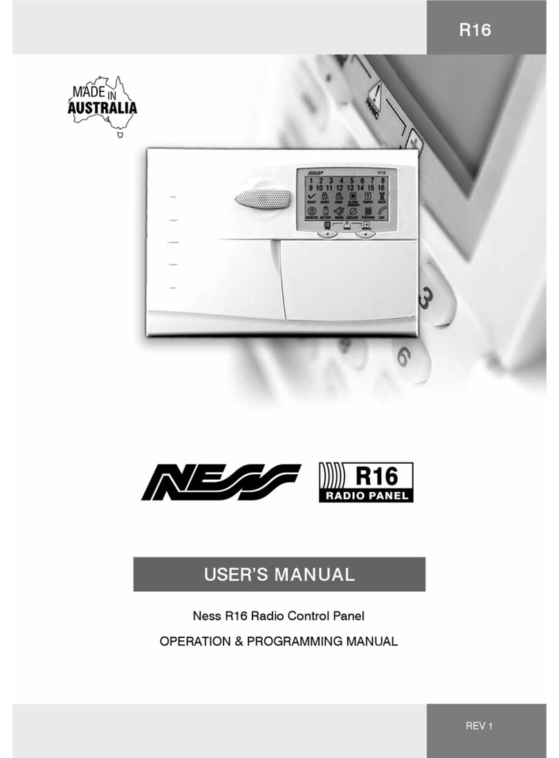
Ness
Ness R16 user manual
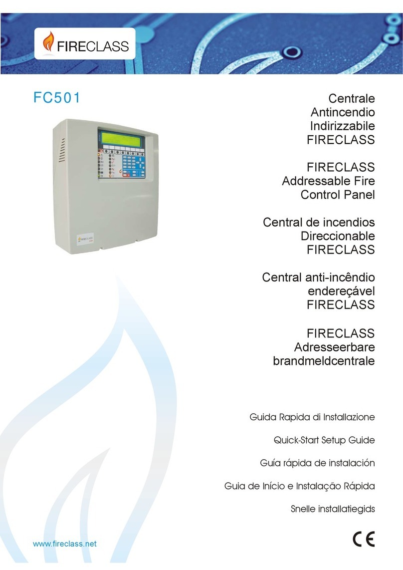
FireClass
FireClass FC501-L Quick start setup guide

weintek
weintek MT-8000 Series installation instructions

Philips
Philips Color Kinetics Power/Data Supply SPDS-60CA... installation instructions

FuelTech
FuelTech SwitchPanel owner's manual
Velux
Velux KLF 200 Setup and user's manual
