manuals.online logo
Brands
  1. Home
  2. •
  3. Brands
  4. •
  5. SJE Rhombus
  6. •
  7. Control Panel
  8. •
  9. SJE Rhombus 115 Operation and maintenance manual

SJE Rhombus 115 Operation and maintenance manual

Single Phase Simplex
SJE Rhombus®Type 115
Installation Instructions and Operation/Troubleshooting Manual
Technical support: +1-800-746-6287
techsupport@sjeinc.com
www.sjerhombus.com
PN 1008706F 05/19
© 2019 SJE, Inc. All Rights Reserved.
SJE RHOMBUS is a trademark of SJE, Inc.
Manufactured by:
Warranty void if panel is modied.
Call factory with servicing questions:
1-800-RHOMBUS
(1-800-746-6287)
This control panel must be installed and serviced by a licensed
electrician in accordance with the National Electric Code NFPA-70,
state and local electrical codes.
All conduit running from the sump or tank to the control panel
must be sealed with conduit sealant to prevent moisture or gases
from entering the panel. NEMA 1 enclosures are for indoor use only,
primarily to provide a degree of protection against contact with en-
closed equipment. Cable connectors are not required to be liquid-tight
in NEMA 1 enclosures. Do not use NEMA 1 enclosures if subjected to
rain, splashing water or hose-directed water. NEMA 4X enclosures
are for indoor or outdoor use, primarily to provide a degree of protec-
tion against corrosion, windblown dust and rain, splashing water and
hose-directed water. Cable connectors must be liquid-tight in NEMA
4X enclosures.
Standard Type 115 panels are designed to operate with two oats.
These oats operate the pump and high level alarm functions. Wide
angle pump switch and SJE Double Float™ applications are illustrated
on next page.
NOTE: Options ordered may aect the number of oats and their
functions. Please reference the schematic provided with the control
panel for proper installation.
Installation of Floats
CAUTION: If control switch cables are not wired and mounted in the
correct order, the pump system will not function properly.
WARNING: Turn o all power before installing oats in pump chamber.
Failure to do so could result in serious or fatal electrical shock.
1. Use oat label kit to label oats for specic operation (stop, lead,
lag, alarm, etc.). See schematic for oat options.
2. Determine your normal operating level, as illustrated in Figures 1
& 2.
3. Mount oat switches at appropriate levels as illustrated in Figure
3. Be sure that oats have free range of motion without touching
each other or other equipment in the basin.
4. For mounting clamp installation: place the cord into the clamp as
shown in Figure 3. Locate the clamp at the desired activation level
and secure the clamp to the discharge pipe as shown in Figure 3.
NOTE: Do not install cord under hose clamp.
5. Tighten the hose clamp using a screwdriver. Over tightening may
result in damage to the plastic clamp. Make sure the oat cable is
not allowed to touch the excess hose clamp band during operation.
NOTE: All hose clamp components are made of 18-8 stainless steel
material. See your SJE Rhombus® supplier for replacements.
Installation
FIGURE 1
SJE Double Float™ system
FIGURE 2
SJE wide angle*oat system
Mounting the Control Panel
1. Determine mounting location for panel. If distance
exceeds the length of either the oat switch cables or
the pump power cables, splicing will be required. For
outdoor or wet installation, we recommend the use of an
SJE Rhombus® liquid-tight junction box with liquid-tight
connectors to make required connections. You must
use conduit sealant to prevent moisture or gases from
entering the panel.
2. Mount control panel (mounting anges are furnished
with control panel).
3. Determine conduit entrance locations on control panel.
Check local codes and schematic for the number of
power circuits required.
NOTE: Be sure the proper power supply voltage, and
phase are the same as the pump motor being installed.
If in doubt, see the pump identication plate for electri-
cal requirements.
4. Drill proper size holes for type of connectors being used.
NOTE: If using conduit, be sure that it is of adequate
size to pull the pump and switch cables through. You
must use conduit sealant to prevent moisture or gases
from entering the panel.
5. Attach cable connectors and/or conduit connectors to
control panel.
FOR INSTALLATION WITHOUT A SPLICE,
GO TO STEP 11; FOR INSTALLATION REQUIRING
A SPLICE, FOLLOW STEPS 6-10.
Installation Instructions
6. Determine location for mounting junction box according
to local code requirements. Do not mount the junction
box inside the sump or basin.
7. Mount junction box to proper support.
8. Run conduit to junction box. Drill proper size holes for
the type of conduit used. Attach connectors to junction
box.
9. Identify and label each wire before pulling through
conduit into control panel and junction box. Pull pump
power cables and control switch cables through connec-
tors into junction box. Make wire splice connections at
junction box.
10. Firmly tighten all ttings on junction box. Insure all cable
connectors are liquid-tight and sealed.
11. If a junction box is not required, identify and label cables
on both oat and stripped ends.
12. Connect pump and oat wires to proper position on ter-
minals. See schematic inside control panel for terminal
connections.
13. Connect alarm and pump power conductors to proper
position on terminals. See schematic inside control
panel for terminal connections.
NOTE: It is the recommendation of the factory to use
separate pump and alarm power sources.
VERIFY CORRECT OPERATION OF CONTROL PANEL
AFTER INSTALLATION IS COMPLETE.
FIGURE 3
Mounting clamp detail
NOTE: Double oat voltage
must match pump voltage.
*Super Single®, SJE PumpMaster® Plus,
or SJE AmpMaster™
(See chart on next page to determine pumping range)
Operations
For information regarding the operations of
options not listed here or servicing questions,
please call a SJE Rhombus®
customer service technician at
1-800-RHOMBUS
(1-800-746-6287)
Warranty void if panel is modied.
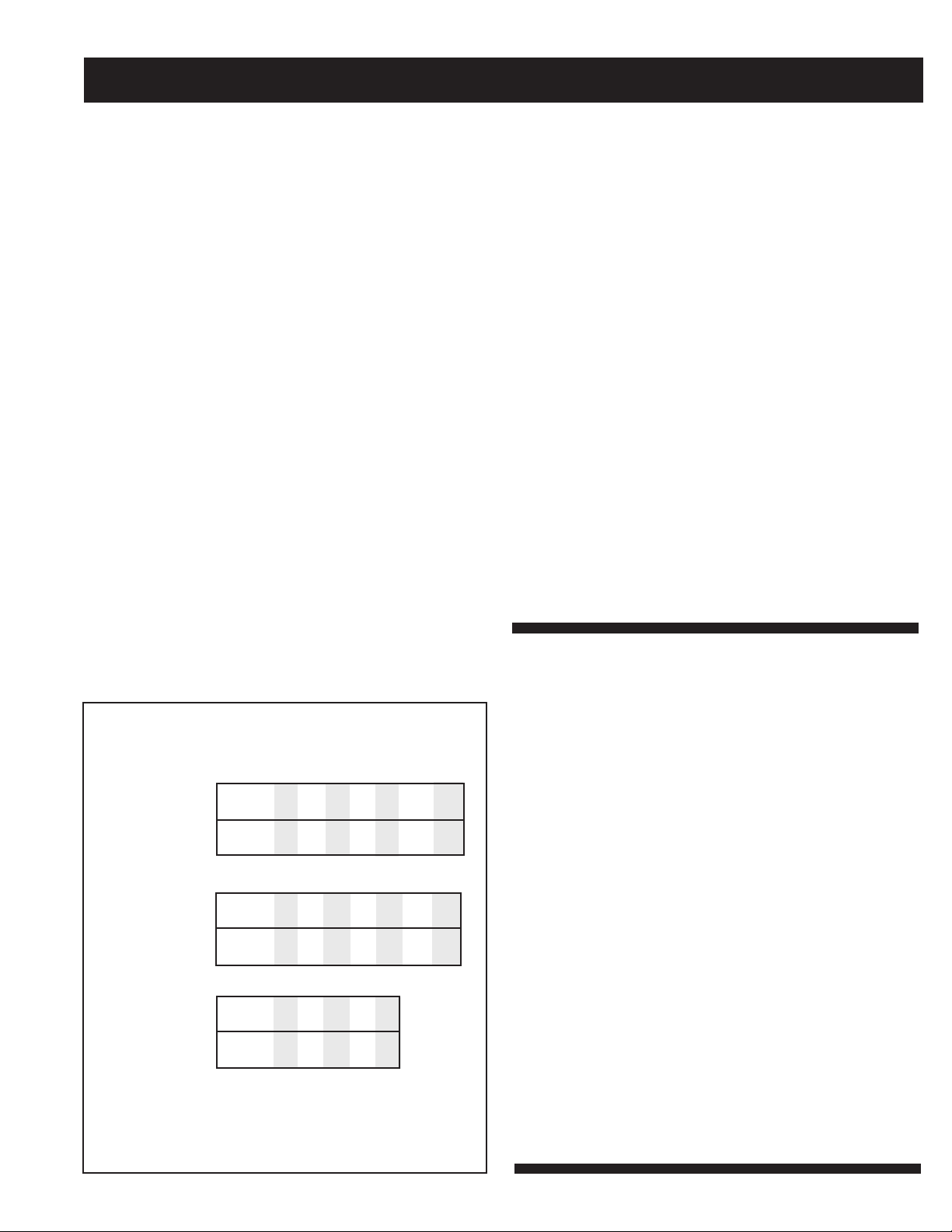
DETERMINING PUMPING RANGE
(IN INCHES)
Use only as a guide. Pumping ranges are based on testing in
non-turbulent conditions. Range may vary due to water tem-
perature and cord shape. Note: As the tether length increases,
so does the variance of the pumping range.
Super Single®
pumping range
tether
length
pumping
range
SJE
PumpMaster
Plus®
pumping range
tether
length
pumping
range
3.5 6 10 14 18 22 24
7 10 16 22 28 33
36
6.5 7.5 8.5 10 11
12.5 13.5
3.5 5 7 9 11 13 15
SJE AmpMaster™
pumping range
tether
length
pumping
range
9 13 17 21 24
5 10 14 18 22
SJE Rhombus® Type 115 control panels are single
phase simplex panels designed for use with wide angle
pump switches, or an SJE Double Float™ and an alarm
switch. When all oats are open or in the OFF position,
the panel is inactive. As the liquid level changes and
closes the pump switch, the pump will start, providing
the HOA switch is in the AUTOMATIC mode and the
power is ON. If a Double Float™ is used, both oats
must be in the ON position before the pump will start.
The pump will remain ON until both oats are returned
to the OFF position. If the liquid level travels beyond
the pump switch or Double Float™ and reaches the
alarm oat, the audio/visual alarm will be activated.
The alarm horn can be silenced by moving the test/
normal/silence switch to the silence position.
Alarm System (Horn and Indicator )
When an alarm condition occurs, a red light and a horn
will be activated. If the test/normal/silence switch is
moved to the silence position, the horn will be silenced.
When the alarm condition is cleared, the alarm system
is reset. The alarm system can be tested by moving
the test/normal/silence switch to the test position.
Alarm Fuse
The alarm circuit contains a bayonett-style fuse dis-
connect. When the fuse is removed, power is cut o
and the alarm circuit is inoperable.
HOA Switch
A hand-o-automatic switch is provided for the pump.
In the hand mode, the pump will turn on unless other
safety features are employed. In the automatic mode,
the pump will turn on from commands by the oat
switches.
Pump Run Light
The run light will be ON in either the hand or the auto-
matic mode when the pump is called to run.
Circuit Breaker (optional)
The pump circuit has a thermal-magnetic circuit
breaker which provides pump disconnect and branch
circuit protection.
Dry Auxiliary Contacts (optional)
Normally Open - Contacts are open under normal con-
dictions and closed when alarm conditions is present.
Normally Closed - Contacts are closed under normal
conditions and open when alarm condition is present.
Both types automatically reset once alarm condition
is cleared.
1. Isolate the oat by disconnecting one or both of the
oat leads from the oat terminals.
2. Place one ohmmeter lead on one of the oat wires, and
the other ohmmeter lead on the other oat wire.
3. Place the ohmmeter dial to read ohms and place on
the R X 1 scale. With the oat in the “o” position, the
scale should read innity (high resistance). Replace
the oat if you do not get this reading. With the oat
in the ON position, the scale should read nearly zero
(very low resistance). Replace the oat if you do not
get this reading.
NOTE: Readings may vary depending on the length of wire
and accuracy of the measuring device.
Fuses
Check the continuity of the fuse. With power OFF, pull the
fuse out of the fuse block. With the ohmmeter on the R X 1
scale, measure resistance. A reading of innity indicates a
blown fuse and must be replaced. Replace fuse with same
type, voltage and amp rating.
Indicator Light
If defective, replace all indicator lights with same type.
Alarm Horn
Moving the test/nor-
mal/silence switch to
the test position or
activating the alarm
oat should turn on
the alarm horn. If the
horn does not sound,
replace horn with same type.
Alarm Light
Moving the test/normal/silence switch to the test position
or activating the alarm oat should turn on the alarm light.
If the light does not activate, replace light with same type.
Circuit Breaker (optional)
Check each pole of the circuit breaker for proper resistance
reading using the following procedure.
WARNING: Disconnect incoming power to panel.
1. Isolate the circuit breaker by disconnecting either line
side or load side wires.
2. Place the ohmmeter leads across the corresponding
line and load terminals of each pole.
3. With the ohmmeter on the R X 1 scale and the breaker
in the OFF position, the reading should be innity (very
high resistance). With the breaker in the ON position,
the reading should be nearly zero ohms (very low resis-
tance). If the readings are not as stated, replace the
circuit breaker with one of the same ratings.
NOTE: Readings may vary slightly depending on the
accuracy of the measuring device.
Float Controls
Check the oats during their entire range of operation.
Clean, adjust, or replace damaged oats.
Checking the oat resistance - The oat resistance can
be measured to determine if the oat is operating correctly
or is defective. Use the following procedure to measure
the oat resistance.
WARNING: Disconnect incoming power to panel.
Troubleshooting
For complete terms and conditions, please visit www.sjerhombus.com.
SJE Rhombus®Five-Year Limited Warranty
NOTICE!
Products returned must be cleaned, sanitized, or decontaminated as necessary prior to shipment to ensure that employees
will not be exposed to health hazards in handling said material. All applicable laws and regulations shall apply.

Other SJE Rhombus Control Panel manuals

SJE Rhombus 123 User manual

SJE Rhombus

SJE Rhombus 123 User manual

SJE Rhombus WellZone User manual

SJE Rhombus

SJE Rhombus WellZone User manual

SJE Rhombus VS21-10.0-N3RD User manual

SJE Rhombus

SJE Rhombus VS21-10.0-N3RD User manual

SJE Rhombus In-Site EZ Series User manual

SJE Rhombus

SJE Rhombus In-Site EZ Series User manual

SJE Rhombus 123 User manual

SJE Rhombus

SJE Rhombus 123 User manual

SJE Rhombus NEMA 4X User manual

SJE Rhombus

SJE Rhombus NEMA 4X User manual

SJE Rhombus H2O Drive RD150 User manual

SJE Rhombus

SJE Rhombus H2O Drive RD150 User manual

SJE Rhombus Installer Friendly Series User manual

SJE Rhombus

SJE Rhombus Installer Friendly Series User manual

SJE Rhombus Three Phase Duplex User manual

SJE Rhombus

SJE Rhombus Three Phase Duplex User manual

SJE Rhombus 122 User manual

SJE Rhombus

SJE Rhombus 122 User manual

SJE Rhombus TimeZone Troubleshooting guide

SJE Rhombus

SJE Rhombus TimeZone Troubleshooting guide

SJE Rhombus Installer Friendly Series User manual

SJE Rhombus

SJE Rhombus Installer Friendly Series User manual

SJE Rhombus 112 Operation and maintenance manual

SJE Rhombus

SJE Rhombus 112 Operation and maintenance manual

SJE Rhombus EZS User manual

SJE Rhombus

SJE Rhombus EZS User manual

SJE Rhombus IFS User manual

SJE Rhombus

SJE Rhombus IFS User manual

SJE Rhombus 124 User manual

SJE Rhombus

SJE Rhombus 124 User manual

Popular Control Panel manuals by other brands

Autocall 4100ES manual

Autocall

Autocall 4100ES manual

DSC PC4020 -  2 installation manual

DSC

DSC PC4020 - 2 installation manual

Crow Serenity Series user guide

Crow

Crow Serenity Series user guide

Cofem LYON user manual

Cofem

Cofem LYON user manual

IPC Galax-H instruction manual

IPC

IPC Galax-H instruction manual

Optex MDC-16ET user guide

Optex

Optex MDC-16ET user guide

AERMEC WRC1 user manual

AERMEC

AERMEC WRC1 user manual

Siemens LED-3 installation instructions

Siemens

Siemens LED-3 installation instructions

Xantrex 710-0010 owner's guide

Xantrex

Xantrex 710-0010 owner's guide

Elkron HI-Connect MP500/4 user manual

Elkron

Elkron HI-Connect MP500/4 user manual

RDZ PC 300 Plus user manual

RDZ

RDZ PC 300 Plus user manual

Graco Therm-O-Flow 243698 instructions

Graco

Graco Therm-O-Flow 243698 instructions

TIS LUNA-OUT-3S-BELL installation manual

TIS

TIS LUNA-OUT-3S-BELL installation manual

Haes ESPRIT-G Installation, commissioning & operating  manual

Haes

Haes ESPRIT-G Installation, commissioning & operating manual

NAPCO Gemini GEM-P1632 Programming instructions

NAPCO

NAPCO Gemini GEM-P1632 Programming instructions

Altimium CP8N user manual

Altimium

Altimium CP8N user manual

ePropulsion Side Mount Control user manual

ePropulsion

ePropulsion Side Mount Control user manual

Thermona RC03 manual

Thermona

Thermona RC03 manual

manuals.online logo
manuals.online logoBrands
  • About & Mission
  • Contact us
  • Privacy Policy
  • Terms and Conditions

Copyright 2025 Manuals.Online. All Rights Reserved.