CAME ZLX24S User manual

FA01797-EN
88006-0085
EN English
CAME S.p.A.
Via Martiri della
Libertà, 15
31030 Dosson di Casier
Treviso - Italy
Tel. (+39) 0422 4940
Fax (+39) 0422 4941
www.came.com
DESCRIPTION OF PARTS
KIT components
1Control board ZLX24S (801QA-
0060 / 801QA-0080)
2Control board holder
3Terminal block with fuse
compartment
4Fuse 4 A (line 120 V)
5Fuse 3.15 A (line 230 V)
6Two 2-pole terminal blocks
FA01797-EN - 05/2022
88006-0085

2- Manual FA01797-EN - 05/2022 - © CAME S.p.A. - The contents of this manual may be changed at any time and without notice. - Translation of the original instructions
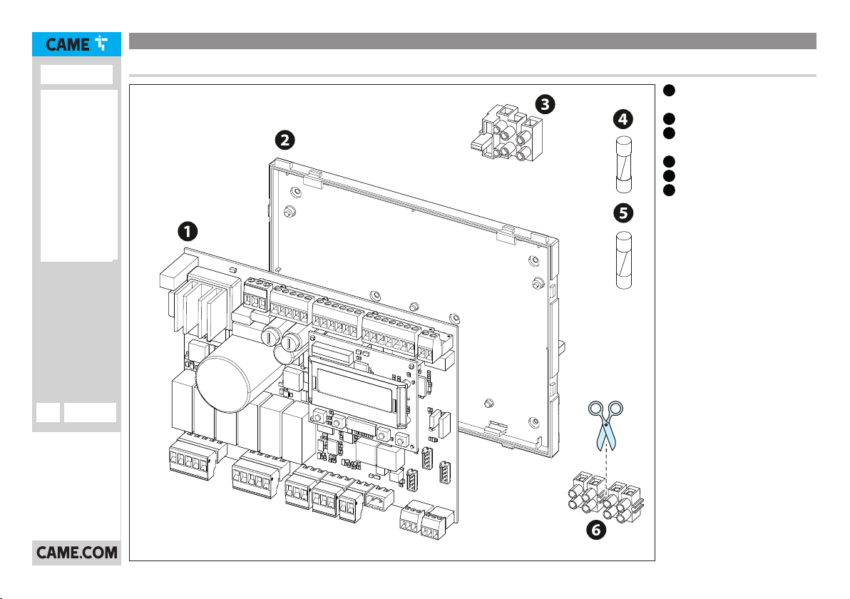
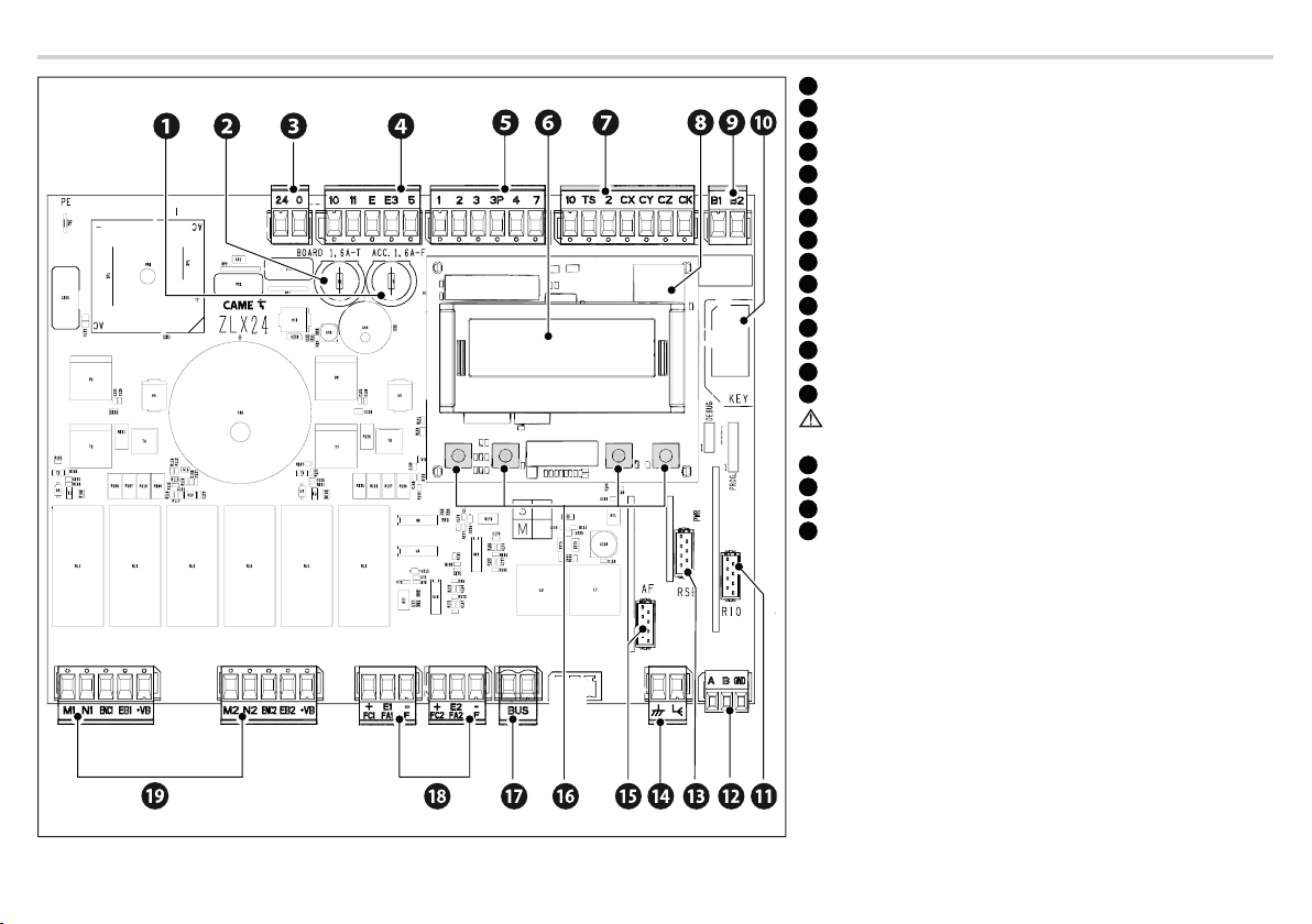
Description of control board components
1Accessories fuse
2Control board fuse
3Terminal board for power supply to the control board
4Terminal board for connecting the signalling devices
5Terminal board for connecting control devices
6Display
7Terminal board for connecting the safety devices
8Memory Roll card connector
9Terminal board for B1-B2 output
10 Connector for CAME KEY*
11 RIO CONN card connector*
12 Terminal board for CRP connection**
13 RSE card connector**
14 Terminal board for connecting the antenna
15 Connector for plug-in radio frequency card (AF)
Use only AF43S or AF868 with diagram number DIS29101 or
above.
16 Programming buttons
17 Terminal board for BUS devices*
18 Terminal boards for connecting micro limit switches and/or encoders
19 Terminal board for connecting the gearmotor with encoder or with
slowdown switch and electric lock
(*) Cannot be used
(**) Not suitable for spare part ZL19N

3- Manual FA01797-EN - 05/2022 - © CAME S.p.A. - The contents of this manual may be changed at any time and without notice. - Translation of the original instructions
INSTALLATION
AControl board support fixing point
BFuse holder terminal block fixing point
Screws not provided. Reuse the screws in the ZL19N or ZLJ24
control panel.

4- Manual FA01797-EN - 05/2022 - © CAME S.p.A. - The contents of this manual may be changed at any time and without notice. - Translation of the original instructions
ELECTRICAL CONNECTIONS
Before working on the control panel, cut o the mains power supply.
Always insert the line fuse in the terminal block.

5- Manual FA01797-EN - 05/2022 - © CAME S.p.A. - The contents of this manual may be changed at any time and without notice. - Translation of the original instructions
ZLJ24 control panel
①Blue cable
②White cable
③Red cable
④Black cable
⑤Orange cable
⑥Purple cable
120 / 230 V AC
ZLJ24
L1T L2T
24 12 0
THERMALS
L N
24 12 0
L1T L2T

6- Manual FA01797-EN - 05/2022 - © CAME S.p.A. - The contents of this manual may be changed at any time and without notice. - Translation of the original instructions
②White cable
④Black cable
⑤Orange cable
⑥Purple cable
Cable not provided
ZLX24
120 / 230 V AC

7- Manual FA01797-EN - 05/2022 - © CAME S.p.A. - The contents of this manual may be changed at any time and without notice. - Translation of the original instructions
ZL19N control panel
①Blue cable
②White cable
③Red cable
④Black cable
⑤Orange cable
⑥Purple cable
⑦Brown cable
⑧Blue cable
L1T L2T
THERMAL PROT
120 / 230 V AC
L N
ZL19N

8- Manual FA01797-EN - 05/2022 - © CAME S.p.A. - The contents of this manual may be changed at any time and without notice. - Translation of the original instructions
②White cable
④Black cable
⑤Orange cable
⑥Purple cable
Cable not provided
ZLX24
120 / 230 V AC

9- Manual FA01797-EN - 05/2022 - © CAME S.p.A. - The contents of this manual may be changed at any time and without notice. - Translation of the original instructions
Maximum capacity of contacts
The total power of the outputs listed below must not exceed the maximum output power [Accessories]
Device Output Power supply (V) Maximum power (W)
Accessories 10 - 11 26 AC 20
Additional light 10 - E3 26 AC 10
Flashing beacon 10 - E 26 AC 10
Operator status warning light 10 - 5 26 AC 3
The outputs deliver 24 V DC when the batteries start operating, if they are installed.
Device Output Power supply (V) Power (W)
Auxiliary contact B1 - B2 - 24 (24V AC/DC)
Connecting gearmotors without R interface (control board 119RIR267)
Connection with slowdown microswitch Connection with limit-switch/slowdown microswitch
FC1 FA1 F FC2 FA2 F
M
N
R
RA
RC
N
M
RC
RA
M1 N1 ENC1 EB1+VB
R1 M2 N2 ENC2 EB2+VB
R2
M1 M2
R
FC1 FA1 F FC2 FA2 F
M
N
F
FA
RC
N
M
RC
FA
F
M1 N1 ENC1 EB1+VB
R1 M2 N2 ENC2 EB2+VB
R2
M1 M2
R
R
Set the function [F72 - Limit-switch function] taking into account the chosen connection.

10 - Manual FA01797-EN - 05/2022 - © CAME S.p.A. - The contents of this manual may be changed at any time and without notice. - Translation of the original instructions
Command and control devices
1STOP button (NC contact)
Stop the gate and exclude automatic closing. Use a control device to resume movement.
When the contact is being used, it must be activated during programming.
2Control device (NO contact)
OPEN ONLY function
When the [HOLD-TO-RUN] function is active, the control device must be connected
during OPENING.
3Control device (NO contact)
PARTIAL OPENING or PEDESTRIAN OPENING function
See [Adjusting partial opening] function.
4Control device (NO contact)
CLOSE ONLY function
When the [HOLD-TO-RUN] function is active, the control device must be connected
during CLOSING.
5Control device (NO contact)
OPEN-CLOSE function
OPEN-STOP-CLOSE-STOP function
See control function 2-7.
6Antenna with RG58 cable
1 2 3 3P 4 7
BUS

11 - Manual FA01797-EN - 05/2022 - © CAME S.p.A. - The contents of this manual may be changed at any time and without notice. - Translation of the original instructions
Signalling devices
1Flashing beacon
It flashes when the operator opens and closes.
2Additional light
It increases the light in the manoeuvring area.
See [Additional light] function.
3Operator status warning light
It notifies the user of the operator status.
See function [Passage-open warning light].
10 11 E E3 5

12 - Manual FA01797-EN - 05/2022 - © CAME S.p.A. - The contents of this manual may be changed at any time and without notice. - Translation of the original instructions
Safety devices
During programming, configure the type of action that must be performed by the device connected to the input.
Connect the safety devices to the CX and/or CY and/or CZ and/or CK inputs.
If used, the contacts CX CY CZ CK must be configured during programming.
For systems with multiple pairs of photocells, please see the manual for the relevant accessory.
DELTA photocells
Standard connection Connection with safety test
See [Safety devices test] function.
10 TS 2 CX CY CZ CK10 11 E E3 5
+
10
-
11 NO C NC +
10
-
11
RX TX
10 TS 2 CX CY CZ CK10 11 E E3 5
+
10
-
11 NO C NC +
10
-
11
RX TX

13 - Manual FA01797-EN - 05/2022 - © CAME S.p.A. - The contents of this manual may be changed at any time and without notice. - Translation of the original instructions
DIR / DELTA-S photocells
Standard connection Connection with safety test
See [Safety devices test] function.
10 TS 2 CX CY CZ CK10 11 E E3 5
+
10
-
2TXCNC +
TX
-
2
RX TX
10 TS 2 CX CY CZ CK10 11 E E3 5
+
10
-
2TXCNC +
TX
-
2
RX TX

14 - Manual FA01797-EN - 05/2022 - © CAME S.p.A. - The contents of this manual may be changed at any time and without notice. - Translation of the original instructions
DXR/DLX photocells
Standard connection Connection with safety test
See [Safety devices test] function.
10 TS 2 CX CY CZ CK
10 11 E E3 5
RX TX
10 11 OUT 10 11 SY
+ -
10 TS 2 CX CY CZ CK
10 11 E E3 5
RX TX
10 11 OUT 10 11 SY
+ -
DFWN sensitive edge
10 TS 2 CX CY CZ CK10 11 E E3 5
CNONC
DFWN

15 - Manual FA01797-EN - 05/2022 - © CAME S.p.A. - The contents of this manual may be changed at any time and without notice. - Translation of the original instructions
PROGRAMMING
Programming button functions
1ESC button
The ESC button is used to perform the operations described below.
Exit the menu
Delete the changes
Go back to the previous screen
Stop the operator
2< > buttons
The <> buttons are used to perform the operations described below.
Navigate the menu
Increase or decrease values
3ENTER button
The ENTER button is used to perform the operations described below.
Access menus
Confirm choice
Outside the menu, the ESC key stops the gate and the < > keys open and close the gate.
Getting started
Once the electrical connections have been made, proceed with commissioning. Only skilled and qualified sta may perform this operation.
Please see the full control panel manual for information on the additional functions relating to the encoder, limit switch and slowdown switches.
Make sure that there are no obstacles in the way.
Power up the device and begin programming.
With mechanical and electronic stops, follow the configuration below.

16 - Manual FA01797-EN - 05/2022 - © CAME S.p.A. - The contents of this manual may be changed at any time and without notice. - Translation of the original instructions
GENERIC MOTOR
Configuration> Motor settings>
Motor type
Generic
Number of motors
Motor test
The > button opens gate leaf M2
The < button opens gate leaf M1
Check that both leaves open. If they do not, invert M and N on the relevant terminal.
Configuration> Wired safety devices>
CX input
CY input
CZ input
CK input
Configuration> Motor settings>
Limit-switch function*
O
With the limit switches deactivated, the stop point is defined by mechanical stops on the ground.
Stop in FA, stop in FC
Slowdown in FA/FC (Default)
Stop in FA, slowdown in FC
Input type FC/FA*
N.O. (Default)
N.C.
N.C. for FA input, N.O. for FC input
Motor power
Minimum power [up to 120W]
Medium power (Default) [up to 200W]
Maximum power [more than 200W]
Travel calibration
*Only with end-of-travel microswitches used.
If CALIBRATION REQUIRED appears on the display, you must calibrate the travel. The panel will not accept motion commands, except for the motor test.
Complete programming and check the warning and safety devices are working properly.
After powering up the system, the first manoeuvre is always to open the gate Wait for the manoeuvre to be completed.

17 - Manual FA01797-EN - 05/2022 - © CAME S.p.A. - The contents of this manual may be changed at any time and without notice. - Translation of the original instructions
Press the ESC button or STOP button immediately in the event of any faults, malfunctions, strange noises or vibrations, or unexpected behaviour in the system.
GEARMOTORS WITHOUT R INTERFACE (control board 119RIR267)
Configuration> Motor settings>
Motor type
Generic
Number of motors
Motor test
Configuration> Wired safety devices>
CX input
CY input
CZ input
CK input
Configuration> Motor settings>
Limit-switch function
Slowdown in FA/FC (Default)
Select the parameter if both microswitches are used for slowdown.
Stop in FA, slowdown in FC
Select the parameter if the opening microswitch is used as a limit switch.
Input type FC/FA
N.O. (Default)
Select the parameter if both microswitches are normally open.
N.C. for FA input, N.O. for FC input
Select the parameter if the closing microswitch is normally open and the opening microswitch is normally closed.
Motor power
Minimum power [up to 120W]
Medium power (Default) [up to 200W]
Maximum power [more than 200W]
Configuration> Gate travel settings>
Opening approach space
Closing approach space Set a value below 5%
Slowdown AST control
Deactivated (Default)
Configuration> Motor settings>
Travel calibration

18 - Manual FA01797-EN - 05/2022 - © CAME S.p.A. - The contents of this manual may be changed at any time and without notice. - Translation of the original instructions
If CALIBRATION REQUIRED appears on the display, you must calibrate the travel. The panel will not accept motion commands, except for the motor test.
Complete programming and check the warning and safety devices are working properly.
After powering up the system, the first manoeuvre is always to open the gate Wait for the manoeuvre to be completed.
Press the ESC button or STOP button immediately in the event of any faults, malfunctions, strange noises or vibrations, or unexpected behaviour in the system.

19 - Manual FA01797-EN - 05/2022 - © CAME S.p.A. - The contents of this manual may be changed at any time and without notice. - Translation of the original instructions
Functions menu
Configuration > Motor settings Number of motors M1+M2 (Default)
M2
Configuration > Motor settings Motor type Generic
STYLO-ME
STYLO-RME
FTX
FAST-70
AXI
AMICO
FERNI
FERNI-V
AXO
A3024N/A5024N
FROG-A24
FROG-A24E (Default)
ATS
F1024
F4024E
F4024EP
Configuration > Motor settings Encoder Activated (Default)
O
Configuration > Motor settings Reduce speed Deactivated (Default)
1% to 50%
Configuration > Motor settings Limit-switch function O
Stop in FA, stop in FC
Slowdown in FA/FC (Default)
Stop in FA, slowdown in FC
Configuration > Input type FC/FA N.O. (Default)
N.C.
N.C. for FA input, N.O. for FC input
Configuration > Motor settings Motor test The > button opens gate leaf M2
The < button opens gate leaf M1
Configuration > Motor settings Travel calibration

20 - Manual FA01797-EN - 05/2022 - © CAME S.p.A. - The contents of this manual may be changed at any time and without notice. - Translation of the original instructions
Configuration > Motor settings Motor power Minimum power [up to 120W]
Medium power (Default) [up to 200W]
Maximum power [more than 200W]
Configuration > Motor settings Configure motor M1 Motor type
Encoder
Limit-switch function
Input type FC/FA
Motor power
See the specific parameters for each function.
Configuration > Motor settings Configure motor M2 Motor type
Encoder
Limit-switch function
Input type FC/FA
Motor power
See the specific parameters for each function.
Configuration > Gate travel settings Opening speed 40% to 100% (Default 70%)
Configuration > Gate travel settings Closing speed 40% to 100% (Default 70%)
Configuration > Gate travel settings Travel AST control Deactivated (Default)
Maximum thrust and low obstruction
sensitivity.
Minimum
Average
Maximum*
(*) Minimum thrust and high obstruction
sensitivity.
Customised
Customised closing
Customised opening
Configuration > Gate travel settings Adjusting the partial opening 10% to 100% (Default 100%)
Configuration > Gate travel settings Opening approach space 0.5% to 25.0% (Default 8.0%)
Configuration > Gate travel settings Closing approach space 0.5% to 25.0% (Default 8.0%)
This manual suits for next models
2
Table of contents
Other CAME Control Panel manuals
Popular Control Panel manuals by other brands

SPAN
SPAN 1-00200 Series owner's manual

mundoclima
mundoclima KJR-120N(X4W)/BGEF Installation and owner's manual

C & K Systems
C & K Systems System 2316E installation instructions

Pro-face
Pro-face Pro-face ST Series user manual

Entrematic
Entrematic LCU40H installation manual

Security Command
Security Command XR6 user guide

TV One
TV One CC-300 CORIOconsole user guide

wattstopper
wattstopper LP Series Installation & Wiring Reference

SPX FLOW
SPX FLOW Bilge Pump Control Panel instruction manual

Fire-Lite
Fire-Lite MS-2E' MS-4E user guide

Exor
Exor eTOP500 Glass Series operating instructions

Pro-tec
Pro-tec Digilite DL500 Programming and PC Configuration Tool Manual