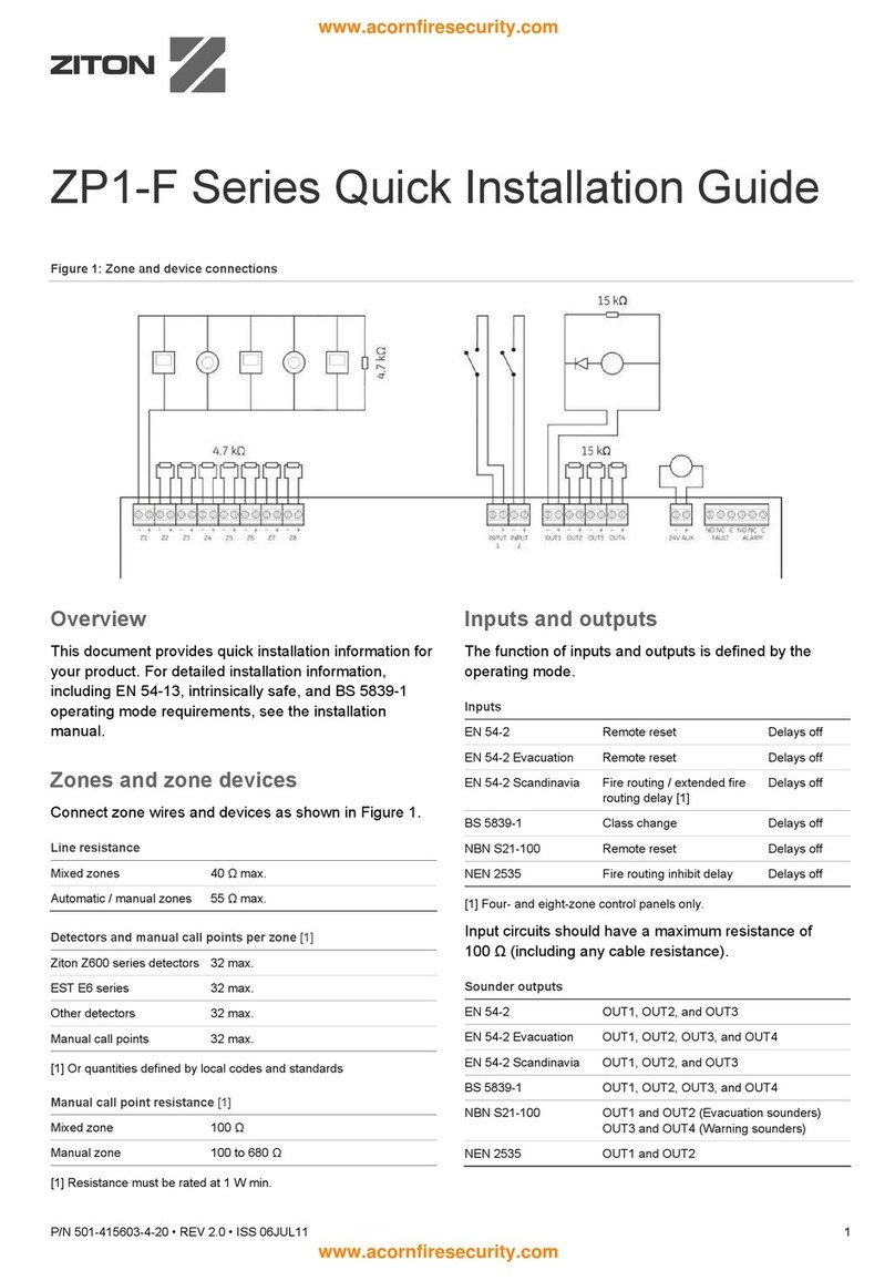
Ziton ZP2 Series User manual

Content
Important information ii
Limitation of liability ii
Advisory messages ii
Introduction 1
Intended audience and purpose 1
Firmware compatibility 1
Installation 2
Registering the 2010-2-PAK-900 2
Connecting loop devices 3
Configuration 4
Detector configuration 4
Sounder configuration 5
Wireless configuration 7
Compatibility 8
www.acornfiresecurity.com

Important information
Limitation of liability
To the maximum extent permitted by applicable law, in no event will UTCFS be
liable for any lost profits or business opportunities, loss of use, business
interruption, loss of data, or any other indirect, special, incidental, or
consequential damages under any theory of liability, whether based in contract,
tort, negligence, product liability, or otherwise. Because some jurisdictions do not
allow the exclusion or limitation of liability for consequential or incidental
damages the preceding limitation may not apply to you. In any event the total
liability of UTCFS shall not exceed the purchase price of the product. The
foregoing limitation will apply to the maximum extent permitted by applicable law,
regardless of whether UTCFS has been advised of the possibility of such
damages and regardless of whether any remedy fails of its essential purpose.
Installation in accordance with this manual, applicable codes, and the instructions
of the authority having jurisdiction is mandatory.
While every precaution has been taken during the preparation of this manual to
ensure the accuracy of its contents, UTCFS assumes no responsibility for errors
or omissions.
Advisory messages
Advisory messages alert you to conditions or practices that can cause unwanted
results. The advisory messages used in this document are shown and described
below.
WARNING: Warning messages advise you of hazards that could result in injury
or loss of life. They tell you which actions to take or to avoid in order to prevent
the injury or loss of life.
Caution: Caution messages advise you of possible equipment damage. They tell
you which actions to take or to avoid in order to prevent the damage.
Note: Note messages advise you of the possible loss of time or effort. They
describe how to avoid the loss. Notes are also used to point out important
information that you should read.
www.acornfiresecurity.com

Introduction
Intended audience and purpose
This manual is intended for those trained and certified to install, program, and
maintain a ZP2 Series control panel. The purpose of this manual is to highlight
the features and functions of the control panels that are specific to the 900 Series
protocol.
For general information on topics not specific to the 900 Series protocol, see your
control panel installation and operation manuals.
Firmware compatibility
Information in this document covers control panels with firmware version 3.5 or
later. This document must not be used as a guide to installation, configuration, or
operation of control panels with an earlier firmware version.
To check the firmware version of your control panel, see the Revision report in
the Reports menu.
www.acornfiresecurity.com

Installation
Registering the 2010-2-PAK-900
A 2010−2-PAK-900 Panel Activation Key (PAK) is required for each control panel
that requires the 900 Series protocol.
Follow these steps to register or unregister the PAK. Installer level access is
required.
To register the PAK:
1. Insert the PAK into either of the USB type A slots on the control panel main
board.
2. On the control panel LCD, select Panel Setup, and then select Panel Activ.
Key.
The LCD displays two options: Register New PAK and Unregister PAK.
3. Select Register New PAK. The PAK information is displayed on the LCD.
Confirm that the details are correct and press Continue.
The PAK information includes: The PAK type, the PAK serial number, and the
host control panel serial number (added when registration is complete).
4. Press Register, and then press Yes to confirm the registration.
5. Press Apply to apply the registration details to the panel, or Continue to
register more PAKs for the same control panel.
To apply the 900 Series protocol:
1. Remove the PAK from the USB slot.
2. Insert a jumper onto JP4 on the control panel main board, and then restart the
control panel.
When the panel restarts, the System Update menu is displayed. This menu is
only available in English.
3. Select Load 900 Series Protocol, and then press the jog dial to confirm the
selection.
4. When the update is complete, remove the jumper from JP4, and then press
Reboot to restart the control panel.
The control panel is now configured to use the 900 Series protocol and devices.
To unregister the PAK:
1. Insert the PAK into either of the USB type A slots on the control panel main
board (see figure).
2. On the control panel LCD, select Panel Setup, and then select Panel Activ.
Key.
3. Select Unregister PAK and follow the on-screen instructions.
www.acornfiresecurity.com

To restore the default protocol:
1. Remove the PAK from the USB slot.
2. Insert a jumper onto JP4 on the control panel main board (see figure), and
then restart the control panel.
When the panel restarts, the System Update menu is displayed. This menu is
only available in English.
3. Select Restore Default Protocol, and then press the jog dial to confirm the
selection.
4. When the update is complete, remove the jumper from JP4, and then press
Reboot to restart the control panel.
The control panel is now configured to use the default protocol and devices.
Connecting loop devices
Using the 900 Series protocol, each loop can support up to 126 devices (using
the address range 1 to 126).
For detailed loop device installation information, see your device installation
sheet.
www.acornfiresecurity.com

Configuration
This section contains information specific to configuring your fire system for the
900 Series protocol. See your control panel installation manual for all other
configuration information.
Note: Configuration options described here require Installer level access. The
default password for the default installer user is 4444.
Detector configuration
Enabling a mounting base
Select the loop device configuration menu to enable a compatible mounting base
and to disable the activation of the remote LED when the detector is in alarm. By
default the mounting base is not enabled (the remote LED is activated when the
detector is in alarm).
If enabled, the remote LED is only activated by output activation configuration or
by rules programming in the Configuratioon Utility application.
To change the configuration:
1. Select Field setup from the Main menu, and then select Loop device config.
2. Select the corresponding loop and device.
The loop device configuration menu displays.
3. Select Base, and then select YES to enable the detector base.
4. Press F4 (Enter), and then press F1 (Back).
5. Press F1 (Save), F3 (Apply), F4 (Discard), or F2 (Exit).
Configuring enhanced heat options
Select the loop device configuration menu to enable enhanced heat options for
compatible CO detectors and multisensors. By default this option is disabled.
If enabled, a fire alarm detected by the device is reported to the control panel as
a prealarm (instead of an alarm). The device is then polled every 60 seconds – if
the temperature rises above the initial temperature plus the configured
temperature gradient (in ºC), the alarm is reported to the control panel. After a
configurable delay (in minutes), an alarm is reported regardless of the
temperature state.
To change the configuration:
1. Select Field setup from the Main menu, and then select Loop device config.
2. Select the corresponding loop and device.
The loop device configuration menu displays.
3. Select and check E_Heat to enable the enhanced heat options.
www.acornfiresecurity.com

4. Select T_Grad, and then enter the temperature gradient (in ºC).
Possible values 1 to 20 (the default value is 5).
5. Select Aly_Dly, and then enter the configurable delay (in minutes).
Possible values 1 to 10 (the default value is 10).
6. Press F4 (Enter), and then press F1 (Back).
7. Press F1 (Save), F3 (Apply), F4 (Discard), or F2 (Exit).
Remember to apply saved settings from the Main menu.
Sounder configuration
Assigning group addresses
Select the loop device configuration menu to assign a group address to control
the simultaneous activation of compatible addressable sounders. By default the
group address value is 0 (the simultaneous activation option is disabled).
Note: At least five compatible sounders are required in a loop to apply
simultaneous activation. For loops with less than five sounders, devices are
activated individually.
To change the configuration:
1. Select Field setup from the Main menu, and then select Loop device config.
2. Select the corresponding loop and device.
The loop device configuration menu displays.
3. Select act_grp, and then assign the required group address.
For device types SDxG, SDx, and SCCx, the group address can be any
number from 112 to 126 that is not already assigned as a device address.
For device types DdG, SDd, SDBd, SDVBd, and SDVd, the group address
can be any number from 1 to 15.
4. Press F4 (Enter), and then press F1 (Back).
5. Press F1 (Save), F3 (Apply), F4 (Discard), or F2 (Exit).
Remember to apply saved settings from the Main menu.
Automatically silencing sounders (noise pollution)
Select the loop device configuration menu to automatically silence compatible
sounders 20 minutes after activation. By default this option is disabled (sounders
continue to sound).
To change the configuration:
1. Select Field setup from the Main menu, and then select Loop device config.
2. Select the corresponding loop and device.
The loop device configuration menu displays.
www.acornfiresecurity.com
3. Select and check NPollut to automatically silence compatible sounders 20
minutes after activation.
4. Press F4 (Enter), and then press F1 (Back).
5. Press F1 (Save), F3 (Apply), F4 (Discard), or F2 (Exit).
Remember to apply saved settings from the Main menu.
Performing walk tests
Select Sounders walk test to perform walk tests for compatible sounders using
the optional magnetic wand accessory (not supplied).
To change the configuration:
1. Select Test from the Main menu, and then select Sounders walk test.
2. Select the loop where the sounders are located, and then press the jog dial to
enable walk test mode for the loop.
While the loop is in walk test mode, use the magnetic wand to locally test
each of the loop sounders.
3. When you have finished, press the jog dial again to exit loop walk test mode.
4. Press F1 (Back) or F2 (Exit).
Adjusting the volume
Select Snd volume walk confg to locally set the volume level for compatible
sounders using the optional magnetic wand accessory (not supplied).
To change the configuration:
1. Select Field setup from the Main menu, and then select Snd Vol Walk Confg.
A list of compatible sounders displays, indicating the device address and
current volume setting.
Move from sounder to sounder and use the magnetic wand to manually adjust
the volume to the required level.
2. When you have finished, press F4 (Enter), and then press F1 (Back).
3. Press F1 (Save), F3 (Apply), F4 (Discard), or F2 (Exit).
Remember to apply saved settings from the Main menu.
www.acornfiresecurity.com
Wireless configuration
Enabling wireless communication
Select the loop device configuration menu to enable wireless communication for
compatible wireless devices. By default this option is disabled.
To change the configuration:
1. Select Field setup from the Main menu, and then select Loop device config.
2. Select the corresponding loop and device.
The loop device configuration menu displays.
3. Select and check Radio to enable wireless communication.
4. Press F4 (Enter), and then press F1 (Back).
5. Press F1 (Save), F3 (Apply), F4 (Discard), or F2 (Exit).
Remember to apply saved settings from the Main menu.
www.acornfiresecurity.com

Compatibility
This section lists the products compatible with your addressable fire system
when using the 900 Series protocol.
Note: Compatible products may change without notice. Always contact your local
supplier to confirm availability and compatibility.
Caution: Products marked with an asterisk (*) are not suitable for installation in
fire systems requiring EN 54-13 compliance.
Mounting bases for addressable devices
Model
Type MFG code Description
DB950
N/A 45681-210 950/990 Series mounting base
DB950B
N/A 45681-361 950/990 Series mounting base black
DB950EZ
N/A 45681-250 950 Series E-Z fit mounting base
DB950R
N/A 45681-242 950 Series low power relay base
DB951
N/A 45681-211 IU950/IU955 intelligent loop isolator base
DB961
N/A 45681-284 950 Series mounting base with isolator
DB970*
N/A 45681-215 970 Series IS detector base
Addressable manual call points
Model
Type MFG code Description
DM950BI
-D* MCPx 245663 950 Series blue manual call point with
isolator (aluminum)
DM950I
-D MCPx 245739 950 Series red manual call point with
isolator (aluminium)
DM980FI
-N MCPd B30120 980 Series red manual call point with
isolator – “feuerwehr” (plastic)
DM980I
-N MCPd B30110 980 Series red manual call point with
isolator – EN 54-11 (plastic)
DMN960I
MCPx 55100-908 950 Series red manual call point - red with
back box and glass
DMN960IE
MCPd 58100-951 990 Series red manual call point with
isolator (surface mount, waterproof)
DM961
* MCPx 950 Series yellow manual call point with
back box and glass
DMN960G
* MCPd 58100-929 990 Series green manual call point with
back box and resettable element
DM980BI
-N* MCPd B30130 980 Series blue manual call point with
isolator – “hausalarm" (plastic)
DM970
MCPx 55100-940 950 Series red IS manual call point (no
flap)
www.acornfiresecurity.com

Addressable point detectors
Model
Type MFG code Description
DP951
ODx 55000-620 950 Series optical detector
DP951B
ODx 55000-660 950 Series black optical detector
DP951T
OHDx 55000-885 950 Series optical/heat detector
DT952
HDx 55000-420 950 Series temperature detector
DT953
HDx 55000-401 950 Series high temperature detector
DI950
IDx 55000-520 950 Series ionisation sensor
DP991
ODd 58000-600 990 Series discovery optical detector
DP991T
OHDd 58000-700 990 Series multisensor
DT992
HDd 58000-400 990 Series heat detector
Addressable zone detectors
Model
Type MFG code Description
FD905R
BDx 55000-268 950 Series reflective beam detector (5 to 50 m)
FD910R
BDx 55000-273 950 Series reflective beam detector (50 to 100 m)
Addressable I/O modules
Model
Type MFG code Description
II950I
SIMx 55000-760 950 Series mini switch monitor with isolator
II952D
SIMx 55000-822 950 Series switch monitor with DIN rail mount
II952I
SIMx 55000-843 950 Series switch monitor with isolator
II953D
SIMx 55000-821 950 Series switch monitor plus with DIN rail mount
II953I
SIMx 55000-841 950 Series switch monitor plus with isolator
II955D
1ZMx 55000-812 950 Series zone monitor unit with isolator and DIN
rail mount
II955I
1ZMx 55000-845 950 Series zone monitor unit with isolator
IO950I
IOx 55000-847 950 Series I/O unit with isolator
IO953I
IOx 55000-588 950 Series 3-channel I/O with isolator and
protective housing
IO954
IOx 55000-875 950 Series mains switching unit
IO955I
IOx 55000-849 950 Series output unit with isolator
IO956CD
SDx 55000-182 950 Series sounder circuit controller with DIN rail
mount (CPD certified)
IO956I
SDx 55000-852 950 Series, sounder circuit controller with isolator
www.acornfiresecurity.com

Loop isolator
Model
Type MFG code Description
IU955
N/A 55000-720 900/950 Series isolator
Addressable notification devices
Model
Type MFG code Description
DB952IAS
SDx 45681-277 950 Series 85/92 dB integrated base sounder with
isolator
DB952IAS
-DIN SDx 45681-300 950 Series 85/92 dB integrated base sounder with
isolator (DIN tone)
DB952IAS
-
NEN
SDx 45681-290 950 Series 85/92 dB integrated base sounder with
isolator (slow whoop)
DB952IVAS
SDx 45681-330 950 Series mounting base with sounder/beacon
and isolator
DB952IVAS
-
DIN
SDx 45681-334 950 Series mounting base with sounder/beacon
and isolator (DIN tone)
AS950I
SDx 45681-266 950 Series loop-powered sounder for isolator base
AS950INEN
SDx 45681-268 950 Series loop-powered sounder for isolator base
(slow whoop)
AS955NEN
SDx 55000-276 950 Series 100 dB loop-powered standalone
sounder (slow whoop)
AS967I
SDx 55000-005 950 Series intelligent loop-powered open area red
sounder/beacon with isolator
AS967WRCI
SDx 55000-006 950 Series intelligent loop-powered open area
white sounder/beacon with isolator (clear lens)
AS964I
SDx 55000-001 950 Series intelligent loop-powered open area red
sounder with isolator
AS964WI
SDx 55000-002 950 Series intelligent loop-powered open area
white sounder with isolator
FA955I
SDx 55000-009 950 Series intelligent loop-powered red beacon
with isolator
FA955WRCI
SDx 55000-010 950 Series intelligent loop-powered white beacon
with isolator (clear lens)
AI952N
IOx AI952N 950 Series loop-powered dual indicator
HSSD detectors [1]
Model
Type MFG code Description
9
-30430 ODs 9-30430 APIC card
9
-30432 ZMUx 9-30432 APIC card (Ampac)
FHSD8010
ODs,
ZMUx FHSD8010 LaserSense Nano high sensitivity smoke detector
www.acornfiresecurity.com
Model
Type MFG code Description
FHSD8025
ODs,
ZMUx FHSD8025 LaserSense 25 high sensitivity smoke detector
FHSD8100
ODs,
ZMUx FHSD8100 LaserSense 100 high sensitivity smoke detector
FHSD8200
ODs,
ZMUx FHSD8200 LaserSense HSSD2 high sensitivity smoke
detector
FHSD8210
ODs,
ZMUx FHSD8210 LaserSense HSSD2 high sensitivity smoke
detector (without display)
FHSD8220
ODs,
ZMUx FHSD8220 LaserSense HSSD2 high sensitivity smoke
detector with integrated command module
FHSD8230
ODs,
ZMUx FHSD8230 LaserSense HSSD2 Command Module
[1] The scope of EN 54-13 covers the listed APIC cards only (and not the HSSD detectors).
Wireless devices
Model
Type MFG code Description
II955IRF
ZMx XPA-IN-
14007-APO Xpander zone monitor unit with isolator
DT934RF
HDx XPA-CB-
11170-APO Xpander A1R heat detector
DT937RF
HDx XPA-CB-
11171-APO Xpander CS heat detector
DP931RF
ODx XPA-CB-
12034-APO Xpander optical detector
DP931TRF
OHDx XPA-CB-
13032-APO Xpander multisensor
DM930RF
MCPx XPA-MC-
14006-APO Xpander manual call point
AS933RRF
SDx XPA-CB-
14001-APO Xpander red sounder and base
AS933WRF
SDx XPA-CB-
14002-APO Xpander white sounder and base
AS936RRF
SDx XPA-CB-
14003-APO Xpander red sounder/beacon and base
AS936ARF
SDx XPA-CB-
14004-APO Xpander amber sounder/beacon and white base
AS936WRF
SDx XPA-CB-
14005-APO Xpander clear sounder/beacon and white base
www.acornfiresecurity.com
Intrinsically safe devices
Model
Type MFG code Description
DP971
* ODx 55000-640 970 Series addressable IS optical sensor
DT972
* HDx 55000-440 970 Series addressable IS heat detector
DB970
* N/A 45681-215 970 Series IS detector base
GBX70
* N/A 29600-098 950 Series IS galvanic barrier
PT971
* N/A 55000-855 970 Series IS 1-channel protocol translator
PT972
* N/A 55000-856 970 Series IS 2-channel protocol translator
www.acornfiresecurity.com
Other manuals for ZP2 Series
3
Table of contents
Other Ziton Control Panel manuals

Ziton
Ziton ZP1-X3E Series User manual

Ziton
Ziton zp1-f Series User manual

Ziton
Ziton zp1-f Series User manual

Ziton
Ziton ZP3 User manual

Ziton
Ziton ZP3 Manual

Ziton
Ziton ZP3 Owner's manual

Ziton
Ziton ZP1-X3E Series User manual

Ziton
Ziton ZP1-X3 User manual

Ziton
Ziton ZP1-X3 User manual

Ziton
Ziton ZP2-F Series User manual
Popular Control Panel manuals by other brands

Philips
Philips RC9800I/00 Specification sheet

Venitem
Venitem CTH-18 Technical manual

Menvier Security
Menvier Security TS690 Operator's manual

Telect
Telect LCX Series installation guide

Digital Monitoring Products
Digital Monitoring Products COMMAND PROCESSOR XR500 installation guide

Bosch
Bosch D9412GV3 installation instructions