Sedgwick TA315 Instruction Manual

TA315
TILT ARBOR SAWBENCH
OPERATION AND MAINTENANCE
INSTRUCTIONS
MACHINE SERIAL NO. TAH

TA Operation/Maintenance Instructions Page 2 of 36
EC Declaration of Conformity
The manufacturer:
M. Sedgwick & Co. Ltd
Stanningley Field Close, Leeds LS13 4QG
United Kingdom
Telephone +44 113 257 0637
www.sedgwick-machinery.co.uk
Email: admin@sedgwick-machinery.co.uk
declares that the Sedgwick TA315 Tilt Arbor Sawbench, when installed, maintained, and
used in applications for which it was designed, and in compliance with the
manufacturer’s instructions, complies with the provisions of the following European Union
legislation, wherever applicable:
2009/127/EC Machinery Directive
2014/30/EC Electromagnetic Compatibility Directive
BS EN ISO 19085-1:2017 Safety of Machinery. Basic Concepts, General Principles of
Design. Basic Terminology, Methodology.
BS EN 1870-19:2013 Safety of woodworking machines. Circular saw benches (with
and without sliding table)
EN 60204-1:2018 Safety of machinery. Electrical equipment of machines. General
requirements
Signed for and on behalf of the manufacturer:
Managing Director
M. Sedgwick & Co. Ltd, Jan 2022

TA Operation/Maintenance Instructions Page 3 of 36
List of Contents
1.0 Design and Purpose
1.1 Illustration
1.2 Machine Specification
1.3 Shipping Details
2.0 Handling Instructions
2.1 Positioning
2.2 Foundation Drawings
3.0 Connection to a Dust Extraction System
4.0 Electrical Installation
5.0 Switchgear
5.1 The Padlockable Isolator
5.2 Start/Stop Buttons
5.3Circuit Protection
5.4 Emergency Foot Operated Stop Switch
6.0 Machine Setting
6.1 The Spindle Rise & Fall
6.2 Tilting The Spindle
6.3 The Rip Fence
6.4 The Rip Fence Fine Adjuster
6.5 The Riving Knife or Splitter
6.7 Pushsticks
6.8 The Rear Extension Table
6.9 Blade Changing
7.0 Blade Selection
7.1 Blade Maintenance
8.0 Limitations of Use and Safe & Working Practices
8.1Noise Reduction
8.2 Warning Labels
9.0 Maintenance
9.1 Cleaning & Lubrication
9.2 620mm Cross Cut Table Setting & Installation
9.3 1220mm Panel Sizing Table Setting & Installation
9.4 Riving Knife Maintenance
9.5 Saw Spindle Maintenance
9.6 Belt Tensioning
9.7 Pulley Alignment
9.8 Rip Fence Alignment
9.9 Electro-magnetic Brake Installation & Maintenance
10.0 Electrical Information
10.1 Electric Motors: Trouble Shooting Checklist
10.2 Wiring Diagrams
11.0 Parts List

TA Operation/Maintenance Instructions Page 4 of 36
Introduction
This Instruction Manual is designed for you in accordance with The Supply of Machinery
(Safety) Regulations 1992, and the Supply of Machinery (Safety) (Amended) Regulations
1994, which implement the European Machinery Directive 89/392/EEC.
It describes how to operate the machine properly and safely. Be sure to follow the safety
instructions provided as well as any local accident prevention regulations and general
safety regulations. Before beginning any work on the machine, ensure that the manual, in
particular the chapter entitled "Safety" and the respective safety guidelines, has been
read in its entirety and fully understood. This manual is an integral part of the machine and
must therefore be always kept accessible. If the machine is sold, rented, lent, or otherwise
transferred to another party, a copy of the manual must accompany it.
All those appointed to work on or with the machine must have fully read and understood
the manual before commencing any work. This requirement must be met even if the
appointed person is familiar with the operation of such a machine or a similar one or has
been trained by the manufacturer.
1.0 Design and Purpose
The Sedgwick Tilting Arbor Sawbench is a hand fed circular ripsaw designed to re-saw
timber and other analogous materials. These operations include Deep Ripping, Angle
Ripping, Bevelling, Cross Cutting, Mitring, Compound Angling, and Panel Cutting.
Any use outside of the machine's intended purpose shall be considered
improper and is therefore not permitted. All claims regarding damage
resulting from improper use that are made against the manufacturer and its
authorised representatives shall be rejected. The operator shall be solely liable
for any damage that results from improper use of the machine.
It is expressly forbidden to make any unauthorised modifications to the machine.

TA Operation/Maintenance Instructions Page 5 of 36
1.1 Illustration
CROSS-CUT FENCE RIVING KNIFE
LENGTH STOP
SAWGUARD
FENCE CLAMP
HANDLES
RIP FENCE
TABLE INSERT
OPTIONAL ROLLING TABLE
FENCE LOCK
TILT LOCKING HANDLE
FENCE MICRO-SET
CONTROL
BLADE TILT
HANDWHEEL
RISE AND FALL HANDWHEEL FRONT GRADUATED GUIDE BAR
EMERGENCY FOOT STOP SWITCH

TA Operation/Maintenance Instructions Page 6 of 36
1.2 Technical Specification
TA315
SAW BLADE DIAMETER
315mm
SAW BLADE BORE
30mm
SAW BLADE PROJECTION @ 900
@ 450
105mm
76mm
SPINDLE SPEED
3700rpm
MOTOR RATING 3ph
1ph
3.0Kw IE2 (S1)
3.0Kw (S1)
SIZE OF TABLE LENGTH
WIDTH
800mm
750mm
HEIGHT OF TABLE
850mm
DISTANCE SAW TO FENCE
610mm
FENCE WITH MICRO ADJUSTMENT
600x75mm
DUST EXTRACTION OUTLET MACHINE
SAWGUARD
150mm
50mm
TOTAL AIR VOLUME REQUIRED
1445CMH
620mm CROSS CUT TABLE
OPTIONAL
TABLE SIZE LENGTH
WIDTH
600mm
350mm
DISTANCE SAW TO MITRE FENCE
620mm
1220mm PANEL SIZING TABLE
OPTIONAL
TABLE SIZE LENGTH
WIDTH
950mm
1000mm
DISTANCE SAW TO MITRE FENCE
1220mm
RIGHT HAND EXTENSION TABLE
OPTIONAL
TABLE SIZE LENGTH
WIDTH
800mm
700mm
DISTANCE SAW TO MITRE FENCE
1220mm
REAR TAKE OFF TABLE
OPTIONAL
TABLE SIZE LENGTH
WIDTH
800mm
700mm
1.3 Shipping Details
TA315
DIMS (machine only) L x W x H
GROSS WEIGHT
1500x1200x1200mm
345 kg
DIMS (c/w 1220mm Panel Table)
DIMENSIONS (Support Bar)
GROSS WEIGHT
1500x1200x1300mm
2720x250x200mm
466 kg

TA Operation/Maintenance Instructions Page 7 of 36
Personal Protective Equipment
When working on or with the machine, the following must be strictly observed:
Persons with long hair who are not wearing a hairnet are not permitted to work on or with
the machine.
It is prohibited to wear gloves while working on or with the machine.
When working on or with the machine, the following must always be worn by personnel:
Protective clothes - Sturdy, tight-fitting clothing (tear-resistant, no wide sleeves).
Protective footwear - that protect the feet from heavy falling objects and prevent sliding
on slippery floors
Hearing protection - To protect against loss of hearing.
Residual Hazards
The machine is considered operationally safe when used properly; nevertheless, there are
some remaining risks that must be considered:
•The machine runs with high electrical voltage.
Electrical energy can cause serious bodily injury. Damaged insulation
materials or defective individual components can cause a life-threatening
electrical shock.
Before carrying out any maintenance, cleaning, and repair work, switch off
the machine and ensure that it cannot be accidentally switched on again. When carrying
out any work on the electrical equipment, ensure that the voltage supply is completely
isolated. Do not remove any safety devices or alter them to prevent them from
functioning correctly.
• Risk of injury when changing the sawblade
• Risk of injury through accidental contact with the rotating sawblade
• Risk of injury due to ejected workpieces
• Risk of injury from workpiece kickback
• Hearing damage as a result of high noise levels
• Health impairments due to the inhalation of airborne particles, especially when working
with beech and oak wood.
The following section offers a guide to transporting, assembling, and installing the
machine. These are all skills that should not be attempted by those who have not received
relevant training.
2.0 Machine Handling
There is a risk of injury as a result of falling parts while transporting, loading or
unloading the machine.
The machine could be damaged or written-off if subjected to improper
handling during transport.
Always use a sling within the safe working load of the machine weight.
Machine weights are provided above. Sling underneath the machine’s cast table. Do not
walk or stand under the machine during lifting.

TA Operation/Maintenance Instructions Page 8 of 36
Storage
Keep the machine sealed in its original packaging until required for assembly/installation
and be sure to observe the machine handling advice on the outside of the packaging.
Store packed items only under the following conditions
• Do not store outdoors.
• Store in a dry and dust-free environment.
• Do not expose to aggressive substances.
• Protect from direct sunlight.
• Avoid subjecting the machine to shocks.
• Storage temperature: –10° to +50 °C
• Maximum humidity 60 %.
• Avoid extreme temperature fluctuations (condensation build-up).
• When storing for a period longer than 3 months, apply a coat of oil to all machine parts
that might be prone to rusting (corrosion protection). Regularly check the general
condition of all parts and the packaging. If necessary, refresh or re-apply a coat of anti-
corrosive agent.
• If the machine is to be stored in a damp environment, it must be sealed in airtight
packaging and protected against corrosion (desiccant).
Disposal
When disposing of the machine, separate all components into material groups in order to
facilitate recycling. The main structure is made of cast iron and steel and can therefore be
safely dismantled and disposed of without risk of pollution.
Unpacking
Dispose of the packaging materials in an environmentally friendly way and
always in accordance with local waste disposal regulations.
Remove the protective grease using turpentine or paraffin. Do not use any
solvent, petrol or gas oil, which might dull or oxidise the paintwork. Lightly oil
cleaned surfaces to prevent rusting.
2.1 Positioning
There should be provided around every woodworking machine sufficient clear and
unobstructed space to enable the work being done at the machine to be done without
risk of injury to persons employed. You must also ensure that there is an ample power
supply available, together with good lighting and ventilation.
Only operate the machine in ambient temperatures from +10° to +40° C. If the
instructions are not followed, damage may occur during storage.
The chosen floor space should be in good and level condition to enable the machine to
be anchored at four points. Holes for M10 foundation bolts (not supplied) are provided at
either corner of the inside of the fabricated body. Remove the machine’s side guard,
score marks through these holes, drag the machine out of the way, and drill the necessary
holes and insert fixing plugs. Finally, make sure that the saw is not rocking. Pack under the
feet of the base if it is. This will keep the saw from rocking and generating vibration during
the cut.

TA Operation/Maintenance Instructions Page 9 of 36
2.2 TA315 Foundation Drawing
1800mm + 620mm for RH Extension
Hole centres for bolting to floor
470mm
1210mm
850mm
685mm

TA Operation/Maintenance Instructions Page 10 of 36
3.0 Connection to a Dust Extraction System
This machine must be connected to a compatible dust extraction unit using a
suitable size and grade of vacuum hose.
Wood dust can be harmful to health by inhalation and skin contact, and concentrations
of small dust particles in the air can form an explosive mixture. Prevention or control of
wood dust exposure should as far as is reasonably practicable, be achieved by measure
other than the provision of personal protective equipment.
Employers have duties under the Provision of Use of Work Equipment Regulations 1998
(PUWER) and the Control Of Substances Hazardous To Health Regulations 1988 to carry out
an adequate assessment of the possible risks to health associated with wood dust
particularly when machining hardwoods, and if necessary seek expert advice as to the
method of dust extraction.
The minimum recommended air volume required to effectively exhaust this machine at
20m/sec is 1400 Cubic Metres per Hour.
A 150mm-dia outlet is located at the rear of the machine base. Provision is also made for
extraction from above the sawguard, simply remove bottom of the 50mm dia connection
point.
Always switch the dust extraction system on before switching on the machine.
4.0 Electrical Installation
All electrical wiring should be carried out by a fully qualified electrician and in
strict observance of the safety instructions.
Please follow these directions when connecting to the mains:
•The motor, starter, and isolator have been wired in at the factory and tested
before despatch. All that is required is to connect the power supply to the
isolator.
•Check that the supply details on the motor nameplate correspond with the site
supply.
•It is important that the correct cable size is used to avoid a voltage drop at the
motor terminals. If the motor is operated on a voltage outside, plus or minus 6%
of the spot voltage, then premature failure will occur.
•Do not wire single-phase machines into a 13 amp plug socket.
•It is important to check rotation of the sawblade which should be clockwise
when viewed from the left of the machine.
Should you encounter problems on start up please refer to the trouble shooting checklist
provided in the Maintenance Instructions.

TA Operation/Maintenance Instructions Page 11 of 36
5.0 Switch Gear
5.1 The Padlockable Isolator
With this switch in the OFF position the machine is effectively isolated from
the supply to allow personnel safe access for maintenance or repair work
and to prevent dangerous restarts. To prevent unauthorised use of the
machine the switch can also be secured in the OFF position using a
padlock.
To operate the machine first turn the isolator to the ON position.
5.2 Start / Stop Buttons
The motor is then started by pushing the green (power on) button on the starter panel and
stopped using the red (power off) button. The mushroom headed lock-off stop switch,
once pressed will remain locked in the off position. To restart the machine, it is necessary
to release the off button by twisting it in a clockwise direction.
5.3 Circuit Protection
In case of a mains failure the starter is fitted with no volt release protection and will not
restart without being switched on again. The starter is also fitted with an overload
protection device. An electrical overload occurs where an electric motor is subjected to a
greater load than it was designed for. This can be caused by short circuit, by incorrect
installation, or by misuse (including poor machine maintenance). The inbuilt breaker will
therefore help prevent damage to the motor should such a situation occur. The motor
cannot be restarted until the breaker has reset itself.
5.4 Emergency Foot Operated Latching Stop Switch
This switch is provided for use in emergency situations only. We do not
recommend that it is used in lieu of the stop switch on the front of the
starter panel. The foot switch once pressed will remain locked in the off
position. To restart the machine, it is necessary to release the switch by
pulling it towards you.
TA Operation/Maintenance Instructions Page 12 of 36
6.0 Machine Setting
Details on the correct setting of the guard, fence and riving knife, together with the use of
the necessary safety devices, are detailed in the following sections of this manual. Prior to
these operations however the following checks should be carried out:
1. The machine is isolated.
2. The saw is not cracked or distorted.
3. The saw collar is clean and in good condition.
4. The sawblade is mounted correctly for clockwise rotation when viewed from left-hand
side of machine.
5. The gap plate is correctly positioned.
6. The saw runs free (check by slowly turning it by hand).
7. The sawguard and riving knife are secure.
8. The timber is free of grit, nails or other foreign bodies.
9. The table is free of spanners, rules etc., and that all tools are returned to their rightful
place.
ENSURE THAT ALL STOCK IS CLEAR OF THE BLADE BEFORE START-UP
ENSURE THAT THE SAWBLADE HAS REACHED FULL SPEED BEFORE PRESENTING THE
WORKPIECE TO IT. IT IS ESSENTIAL THAT THE MACHINE IS SWITCHED OFF WHEN LEFT
UNATTENDED.
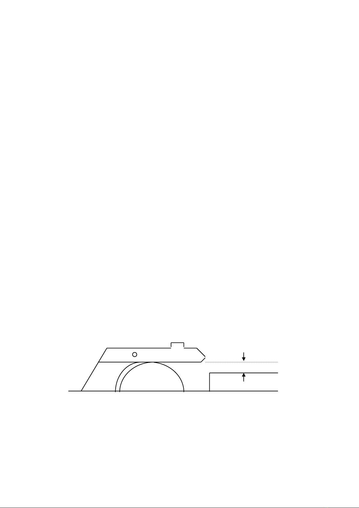
6.1 The Spindle Rise and Fall
The height of the saw spindle is adjusted using the rise and fall handwheel at the front of
the machine.
The blade should be set so that the distance between the bottom edge of the sawguard
and the top of the timber being cut does not exceed 10mm. In this position you should
aim to have 3-5 of the blade’s teeth in the wood during the cut. This will minimise the
amount of friction and enable you to maximise feed speed. Clearly, the thicker the stock
the more teeth there are in the wood. This increases friction, reduces feed speed, and
taxes the saw motor. The solution is to replace the blade with a coarser one. Avoid the
temptation to raise the blade to full height. While the number of teeth in the wood
decreases, the footprint of the blade in the wood is much greater. This increases the
chance of kick-back. There is also a much greater chance of injury with the blade at full
height.
10mm
6.2 Tilting the Spindle
The motor and motor bracket tilt on a quadrant of 450from the vertical, by means of the
handwheel positioned to the side of the machine. The graduated protractor scale at the
front of the saw indicates the angle at which it is set. A locking lever is positioned above
the rise and fall handwheel for locking / unlocking the tilt. Do not attempt to tilt the
sawblade with the lock engaged.
TA Operation/Maintenance Instructions Page 13 of 36
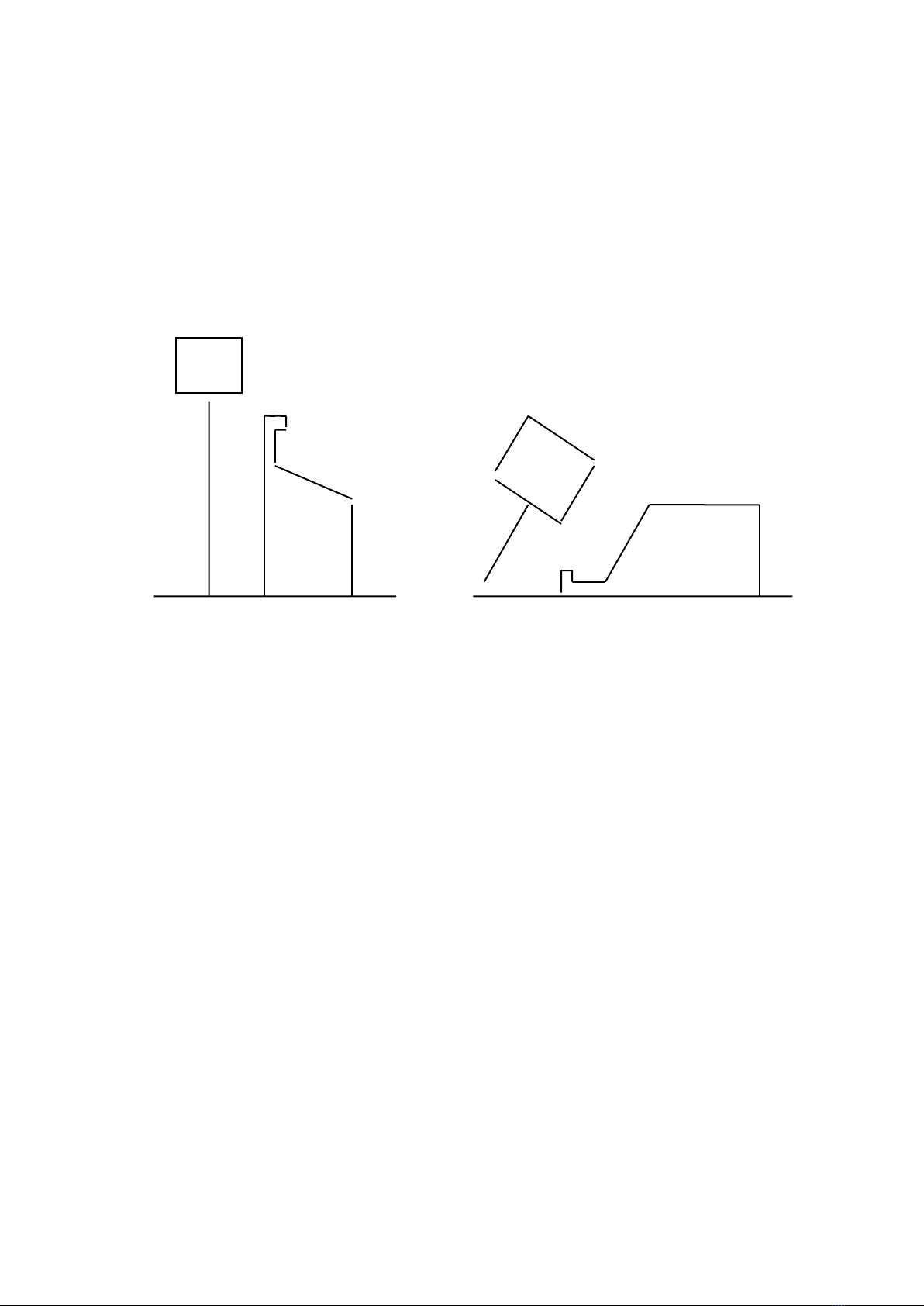
6.3 The Rip Fence
The function of the sawfence is to act as a guide and support to the timber. It can be
adjusted fore and aft to suit the operation being carried out. When ripping, the front edge
of the fence should be in line with the root of the teeth of the sawblade. When
crosscutting, the maximum possible length of fence should lie on the machine table. To
adjust, simply release the two clamping levers at the back of the fence. Note: the fence
casting is eased along its travel by means of a nylon roller. To ensure that the roller remains
in contact with the machine table in all fence positions, the fence extrusion should be set
slightly higher than the table itself. When sawing thin pieces of timber ensure that the two
positional fence is adjusted to suit:
High position for deep work Low position for shallow or angled cutting
6.4 The Rip Fence Fine Adjuster
For approximate setting of the width of cut the table rule can be used, located on the
fence support bar, although the accuracy of this will depend on the sawblade being
used. The most reliable method for setting the width of cut is to measure from the fence to
the inside edge of the tooth. This takes account of different amounts of set on the saw
teeth of other saws. To take account of any wobble on the saw, a trial cut should be
made and measured with a steel rule; then adjustments may need to be made using the
fine adjustment screw. The guards should be in place for the trial cut. Ensure that the
machine is switched off before making any adjustments.
6.5 The Riving Knife or Splitter
The riving knife should be adjusted so that at table level the distance between the front of
the knife and the saw teeth does not exceed 8mm and its arc follows that of the
sawblade.
Its height should be adjusted so that the bottom of the sawguard covers the teeth of the
sawblade. The sawguard must be adjusted so that it is parallel with the machine table
using the sawguard horizontal adjustment.

TA Operation/Maintenance Instructions Page 14 of 36
8mm Max.
6.7 Pushsticks
Pushsticks (provided as standard with this machine) should always be used when making
any cut less than 300mm in length or when feeding the last 300mm of a longer cut, to
avoid working with hands close to the sawblade. The leading hand should never be closer
than is necessary to the front of the saw and hands should never be in line with the saw
blade. When a pushstick is used, the left hand should be moved to a position along the
plate of the saw, so that in the event of an unexpected movement of the workpiece, the
fingers will not be thrown against the teeth.
A pushstick should always be used to remove the cut piece from between the saw and
fence, unless the width of the cut piece exceeds 150mm.
A pushblock should be used when cutting small workpieces or in circumstances where it is
necessary to push the workpiece against the fence.
6.8 The Optional Rear Extension Table
If an assistant is employed at the rear of the machine to remove cut pieces the table
should be extended so the distance between the saw blade spindle and the rear edge of
the table is at least 1200mm. The assistant should always remain at the outfeed end of the
extension table and should not lean forward and put his hands near to the saw teeth.
1200mm

TA Operation/Maintenance Instructions Page 15 of 36
6.9 Blade Changing
Saws should be regularly examined to check that the plate is free from cracks and is true,
that the tips are firmly held in position and damage free. The teeth should be sharpened
the moment they become dull. The Grinding of TCT Sawblades requires specialised
equipment. This creates a tendency to retain the blade in the saw long after initial dulling
takes place. This is a false economy.
To remove the sawblade first isolate the machine, then remove the gap plate. Loosen
screw ‘A’ on the sawguard and tilt the front of the guard upward to expose the blade.
Rotate the blade until one of the holes in the saw spindle (behind the fixed collar) is
exposed through the slot in the cradle plate. Slide the spindle lock bar down the slot and
into the exposed hole. This will prevent the spindle from rotating. Use the Saw Spanner
provided to loosen and remove the securing nut. Note the direction of the thread, left
hand. Finally remove the loose saw collar and blade. The use of a wire hook for
transferring the saw to the tool room reduces the risk of cut fingers and damaged saw
teeth (if the blade is dropped when carrying it by hand).
To replace the blade clean both saw collars, ensure that the sawblade being fitted is
clean and sharp, and place onto the spindle ensuring that the direction of rotation is
correct.
Replace the loose saw collar and saw nut and tighten.
Important: Remove the spindle lock bar prior to replacing the gap plate, levelling the
sawguard, and re-tightening screw ‘A’.
7.0 Blade Selection
The machine’s designation (e.g. TA315) indicates maximum sawblade diameter in mm.
Spindle speed is set accordingly, and we do not recommend the use of smaller diameter
sawblades, which require a much faster running speed. When using a smaller diameter
sawblade , be sure that its rpm rating is correct for the saw. The blade’s peripheral speed
will decrease. This means that feed speed (speed at which stock goes through the blade)
will also decrease. This could mean increased friction and burning. Smaller diameter
blades should have fewer teeth than the larger diameter blade that has been removed.
Do not attempt to use a blade that is less than 200mm dia on the TA315.
All blades will require a 30mm bore and a 14mm pinhole (25mm from centre to centre).
Selecting the correct blade for each operation is an essential link in the sawing process.
Your guarantee will be invalidated if you do not select the correct cutting tools.
The sawblade supplied with the machine is a 32-tooth tungsten carbide tipped anti-kick
back blade, with alternate top bevel and raker teeth to give a good finish for both ripping
and crosscutting applications. Its anti-kick back feature limits the size of bite any tooth can
take, and therefore the grip that the saw has on the wood, giving the operator better
control of the stock. It does however make the blade unsuitable for deep ripping. When
cutting material in excess of 76mm, use a blade which is expressly designed for this
purpose. Misuse will put undue load on the motor, which could cause long-term damage
to the motor windings.
Tungsten Carbide Tipped sawblades will stay sharp for much longer than conventional
saws and will produce a much higher quality of cut. The following table gives examples of
the type of TCT blades available, and their applications:

TA Operation/Maintenance Instructions Page 16 of 36
Type
Description
No.
Teeth
Softwood Rip
For rough ripping of softwoods and green hardwoods.
Large gullet space for chip clearance and rapid cutting
with grain
24
Universal Rip
Ripsawing of both hardwood and softwood and
occasional rough crosscutting. 200tooth angle, 100
alternate bevel.
32
Combination
Rip & Crosscut
General Purpose Blade providing a good finish for both
ripping and crosscutting applications. 100tooth angle, 100
alternate bevel.
48
Trimming
Accurate sizing and trimming of timber, plywoods and
particle boards, veneers, and soft plastics. 100tooth angle,
triple chip.
72
Finishing
Fine trimming and finishing applications for double sided
laminated boards, veneers, and hard plastics. 50 tooth
angle, triple chip.
96
Courtesy of Atkinson Walker
For maximum efficiency, always use the coarsest blade that produces adequate results.
7.1 Blade Maintenance
A dull, badly set or badly ground blade will cause slow, inefficient cutting. It will also
increase the effort required for feeding and possibly overload the saw motor. It is good
practice to have a second set of sharp blades available for when dull ones are away for
sharpening (for saw sharpening services look under ‘SAW SHARPENING & REPAIRS’ in the
Yellow Pages). Deposits of gum or resin near the saw teeth tend to cause a saw to stall or
the timber to stick. This gum can be best removed with trichlorethylene, kerosene or
turpentine. The most common method for cleaning off resin is to use a brush and scrape.
A wooden scraper will avoid unnecessary scratching of the sawblade surface. Never try to
clean a running blade.

TA Operation/Maintenance Instructions Page 17 of 36
8.0 Limitations of Use and Safe Working Practises
Training and instruction is a central requirement of the Provision of Use of Work Equipment
Regualtions 1998 (PUWER). No hand-fed circular saw can be operated by any person
under the age of 18 without them having first completed an approved course of training.
The regulation does realise that young persons may need to operate one of these
machines as part of a course, and such use is permitted provided that it is carried out
under the supervision of a person who has thorough knowledge and experience of the
machine and of its safeguarding requirements.
It is essential that all operators of circular saws are adequately trained in the use,
adjustment and operation of the machine, this covers in particular:
•The dangers associated with the operation of the machine.
•The principles of machine operation, correct use and adjustment of the fence, blade
and safeguards.
•The correct selection of sawblade for each operation.
•The safe handling of the workpiece when cutting.
•The position of the hands relative to the blade and the safe stacking of workpieces
before and after cutting.
Persons who install this machine for use at work have a duty under the Health and Safety
at Work Act 1974 to ensure, as far as is reasonably practicable, that nothing about the
way in which it is installed makes it unsafe or a risk to health at any time during setting, use,
cleaning, and maintenance. This includes such aspects as correct assembly, electrical
installation, construction of enclosures, and the fitting of guards and ventilation
equipment. When installing this machine consideration must be given to the provision of
adequate lighting and working space.
Repairs and maintenance must only be undertaken by competent technicians. Ensure
that all power supplies are isolated before maintenance work begins. Instructions for
routine maintenance work are included in this manual.
The machine is designed to be operated by only one person. If an assistant is employed
to remove cut pieces a table extension must be fitted to the rear of the machine as
detailed above.
No circular sawing machine is to be used for the crosscutting of logs and branches. These
operations relate mainly to the production of firewood and the practice of feeding the
wood by hand to a conventional sawbench is not permitted.
The use of a circular saw for the cutting of any rebate, tenon, or groove is prohibited,
unless the part of the blade above the table is effectively guarded. When it is not
practicable to carry out these operations with the riving knife and top guard in position,
suitable alternative guards and fixtures will be necessary.

TA Operation/Maintenance Instructions Page 18 of 36
8.1 Noise
Noise levels can vary widely from machine to machine depending on conditions of use.
Persons exposed to high noise levels, even for a short time, may experience temporary
partial hearing loss and continuous exposure to high levels can result in permanent
hearing damage. The Woodworking Machines Regulations require employers to take
reasonably practicable measures to reduce noise levels where any person is likely to be
exposed to a continuous equivalent noise level of 90 dB(A) or more over an 8 hour
working day. Additionally, suitable ear protectors must be provided, maintained and
worn.
Machines identified as generating unhealthy noise levels should be appropriately marked
with a warning of the need to wear hearing protection and it may be necessary to
designate particular areas of the workplace as ‘Ear Protection Zones’. Suitable warning
signs are specified in the Safety Signs Regulations Act 1995. It may be necessary to
construct a suitable enclosure, for which professional advice should be sought.
Further information and references to practical guidance are contained in free leaflets
available from The Health & Safety Executive.
Using correctly designed extraction hoods and a compatible system the compound
effect on this machine was to increase the readings by 1dB(A).
The following noise levels were recorded at a distance of one metre from the machine
(operator side) with a 24-tooth anti kick sawblade fitted, using varying feed rates and
depths of cut.
TIMBER
DEPTH OF CUT
NOISE LEVEL dB(A) @ 1M
None
No load
80
Softwood
20mm
85
Softwood
38mm
87
Softwood
75mm
88
Hardwood
20mm
86
Hardwood
38mm
88
Hardwood
75mm
89
The figures quoted for noise are emission levels and not necessarily safe working levels.
Whilst there is a correlation between emission levels and exposure levels, this cannot be
used reliably to determine whether or not further precautions are required. Factors that
influence the actual level of exposure to the work force include the duration of exposure,
the characteristics of the workroom, the other sources of dust and noise, etc., i.e. the
number of machines and other adjacent processes. Also the permissible exposure levels
can vary from country to country. This information, however, will enable the user of the
machine to make a better evaluation of the hazard and risk.
The list below outlines some of the variables which directly effect the noise level of the
machines:
VARIABLE
RELEVANT FACTOR
EFFECT
Timber
Species
Hard stiff timber can mean more noise
(approx. 2dB(A) difference when cutting
oak and pine) & more transmitted noise.
Width
Wide work pieces radiate noise over a
greater area increasing the noise level.

TA Operation/Maintenance Instructions Page 19 of 36
Thickness
Thin workpieces generally vibrate more
increasing the noise level.
Length
Long workpieces transmit noise away
from the cutting area towards the
operator.
Tooling
Width of Blade
This affects the windage noise and
increases roughly in proportion to the
width of cut.
Blade Sharpness
Dull and worn blades exert more force
on the timber thus creating more noise.
Balance
Out of balance blades mean vibration
and changes in cutting conditions,
resulting in increased noise levels.
Extraction
Air Velocity/ System Design
Resonant conditions can lead to high
noise levels, excessive turbulence and
chip impact can increase noise levels
substantially
8.2 Warning Labels
The warning label fixed to the machine gives the following advice. Please ensure that all
operators read it carefully.
Ensure that you fully understand the manufacturer’s
instruction manual and have received sufficient training in
the use of this machine and the particular safety
precautions to be observed.
BEFORE OPERATING THIS MACHINE ENSURE THAT:
1. All guards and fences are securely fitted and correctly
set in accordance with the current regulations.
2. Tooling is of the correct type, sharpness, and direction of
cut and is securely fastened.
3. Correct spindle speed and feed is selected (for the cutter
equipment) where appropriate.
4. Loose clothing is either removed or fastened and
jewellery removed.
5. Suitable jigs and push sticks are available for use where
appropriate.
6. The working area is well lit, clean and unobstructed.
7. Extraction equipment where appropriate is switched on,
properly adjusted and working efficiently.
DURING MACHINING:
1. Wear suitable protective equipment where necessary,
e.g. goggles, ear defenders and dust mask.
2. Ensure all moving parts of the machine are stationary
before setting, cleaning or making any adjustments.
3. Ensure all power sources are isolated before any
maintenance work commences.

TA Operation/Maintenance Instructions Page 20 of 36
General caution
Check guard
Refer to instruction manual
Use hearing protection
Use protective eyewear
Use protective footwear
Use protective apron
Wear a mask
All notices and labels which are affixed to the machine must be kept readable and may
not be removed. Any that have become damaged or unreadable must be replaced
promptly.
Table of contents
Popular Saw manuals by other brands


Target
Target PRO 35 III DIESEL operating instructions

ALDI
ALDI Workzone Titanium HM80MP user manual

Bauer
Bauer 21702CR-B user manual

Skil
Skil 5580 Operating and s Operating and safety instructions

Eurotops
Eurotops 20405 operating instructions

Record Power
Record Power SABRE-250 Original instruction manual


