manuals.online logo
Brands
  1. Home
  2. •
  3. Brands
  4. •
  5. See Water
  6. •
  7. Control Panel
  8. •
  9. See Water Oil Smart OSD1P-102 Series User manual

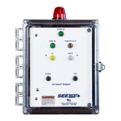
See Water Oil Smart OSD1P-102 Series User manual

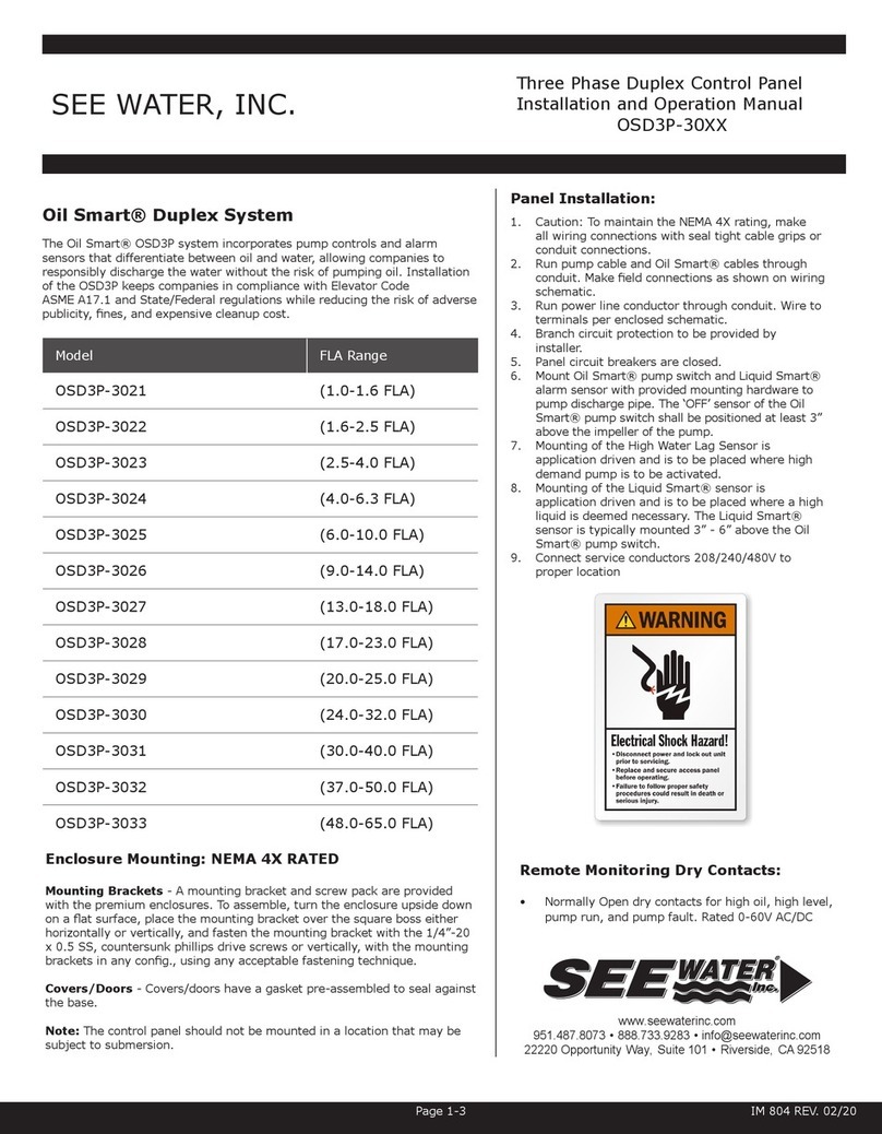
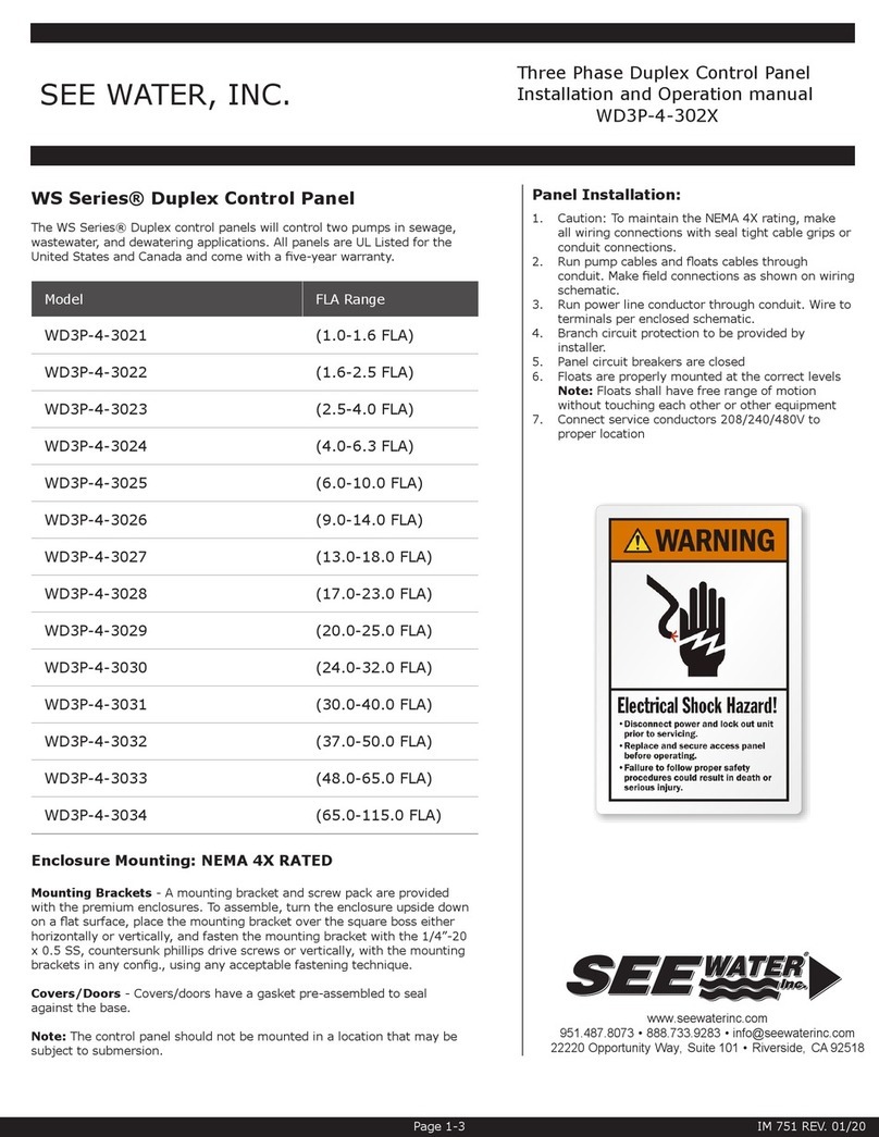
Single Phase Duplex Control Panel
Installation and Operation Manual
OSD1P-102X
SEE WATER, INC.
Panel Installation:
1. Caution: To maintain the NEMA 4X rating, make all
wiring connections with seal tight cable grips or conduit
connections.
2. Run pump cable and Oil Smart® cables through
conduit. Make eld connections as shown on wiring
schematic.
3. Run power line conductor through conduit. Wire to ter-
minals per enclosed schematic.
4. Branch circuit protection to be provided by installer.
5. Panel circuit breakers are closed.
6. Mount Oil Smart® pump switch and Liquid Smart®
alarm sensor with provided mounting hardware to
pump discharge pipe. The ‘OFF’ sensor of the Oil
Smart® pump switch shall be positioned at least 3”
above the impeller of the pump.
7. Mounting of the High Water Lag Sensor is application
driven and is to be placed where high demand pump is
to be activated.
8. Mounting of the Liquid Smart® sensor is application
driven and is to be placed where a high liquid is
deemed necessary. The Liquid Smart® sensor is
typically mounted 3” - 6” above the Oil Smart® pump
switch.
9. Connect service conductors 120/208/240VAC to proper
location.
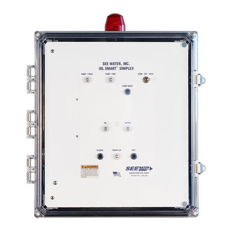
Oil Smart® Duplex System
The Oil Smart® OSD1P system incorporates pump controls and alarm
sensors that differentiate between oil and water, allowing companies to
responsibly discharge the water without the risk of pumping oil. Installation
of the OSD1P keeps companies in compliance with Elevator Code ASME
A17.1 and State/Federal regulations while reducing the risk of adverse
publicity, nes, and expensive cleanup cost.
Model FLA Range
OSD1P-1021 (0.0-7.0 FLA)
OSD1P-1022 (7.0-15.0 FLA)
OSD1P-1023 (15.0-22.0 FLA)
OSD1P-1024 (22.0-28.0 FLA)
OSD1P-1025 (28.0-36.0 FLA)
Enclosure Mounting: NEMA 4X RATED
Mounting Brackets - A mounting bracket and screw pack are provided
with the premium enclosures. To assemble, turn the enclosure upside down
on a at surface, place the mounting bracket over the square boss either
horizontally or vertically, and fasten the mounting bracket with the 1/4”-20
x 0.5 SS, countersunk phillips drive screws or vertically, with the mounting
brackets in any cong., using any acceptable fastening technique.
Covers/Doors - Covers/doors have a gasket pre-assembled to seal
against the base.
Note: The control panel should not be mounted in a location that may be
subject to submersion.
www.seewaterinc.com
951.487.8073 • 888.733.9283 • [email protected]
22220 Opportunity Way, Suite 101 • Riverside, CA 92518
Remote Monitoring Dry Contacts:
• Normally Open dry contacts for high oil, high level,
pump run, and pump fault. Rated 0-60V AC/DC
Page 1-3 IM 752 REV. 02/20
Your Trusted Source for Quality Control Panels.
®
SEE WATER, INC.
Sequence of Operation:
Typical Installation of Oil Smart® Duplex Control Panel
Oil Smart® Duplex Control Panel
Liquid Smart® Alarm Sensor
Oil Smart® Pump Switch
Submersible Pump #1
High Water Sensor
Submersible Pump #2
Normal Condition (Water Only)
When water comes in contact with the
short (on) sensor, the pump will turn
on. The pump will remain on until
water clears the long (off) sensor.
Oil Present Condition
If oil comes in contact with the (on)
sensor, the pump will not turn on.
Operation of Oil Smart®
Water (Oil Present Condition)
If the water level rises enough to
contact the (on) sensor under the
oil layer, the pump will turn on and
remain on until the (off) sensor clears
WATER
WATER
OIL
LAYER
WATER
OIL
LAYER
WATER
WATER
OIL
LAYER
WATER
OIL
LAYER
Operation of Liquid Smart®
High Water Level
When water comes in contact will both
sensors, the white water indicator on
the front panel will illuminate. This
condition will turn on the red beacon
alarm light and sound the alarm buzzer.
High Oil Level
If oil comes in contact with both sensors,
the yellow oil indicator on the front panel
will illuminate. This condition will turn on
the red beacon alarm light and sound the
alarm buzzer.
Single Phase Duplex Control Panel
Installation and Operation Manual
OSD1P-102X
Testing:
Oil Smart® Pump Switch Testing:
• Place your thumb on the short stainless steel sensor
of the Oil Smart® pump switch, and the pump will
turn on. While touching the short ‘ON’ sensor, touch
the long ‘OFF’ sensor with your ngers; remove your
thumb from the short ‘ON’ sensor and begin to move
your ngers down the ‘OFF’ sensor simulating water
being pumped down. Once ngers are removed from
‘OFF’ sensor, the pump will turn off.
• Optional: Fill the sump area with ground water, when
water reaches the ‘ON’ sensor, the pump will turn on
and remain on until water clears the ‘OFF’ sensor.
Liquid Smart® Alarm Testing:
• Submerge both sensors in oil and the yellow oil
indicator on the front panel will illuminate. To test
water sensor, submerge both sensor in ground water
and the white water light will illuminate.
• Both test will illuminate the 360 degree visible beacon
and sound an 85 decibel at 10’ buzzer.
www.seewaterinc.com
951.487.8073 • 888.733.9283 • [email protected]
22220 Opportunity Way, Suite 101 • Riverside, CA 92518
Page 2-3 IM 752 REV. 02/20
SEE WATER, INC.
Troubleshooting:
Caution: Before checking electrical connections within the control or
attempting to replace any components, turn off all branch circuits supplying
power to the main control panel.
Pump control does not activate the pump or pump does not run
• Verify polarity is correct.
• Conrm all connections are tight and secure.
• White plastic case must be kept clean. Clean with house hold rubbing
alcohol and rag.
• Keep control 1” - 2” clear of any metallic material. Mount to PVC pipe
or if mounted to metal pipe, make sure to mount with See Water quick
mount PVC bracket.
Alarm will NOT activate
• Conrm separate 120VAC power to circuit board TS1-1 and TS1-2.
Power can be jumpered from incoming voltage if needed.
• Check for any visual damage to optic or stainless steel sensor on the
Liquid Smart® sensor.
Preventive Maintenance
• The Oil Smart® pump switch and Liquid Smart® sensor must be kept
clean. If the switches are submerged during install or maintenance,
clean the white plastic case with rubbing alcohol. Consistent inspection
and preventive maintenance ensures longevity and proper operation of
components.
Single Phase Duplex Control Panel
Installation and Operation Manual
OSD1P-102X
Additional Panel Options:
24 - Pump Exerciser
• Auto cycles pumps daily, weekly or monthly.
Run Time Options:
• Position A: 50ms (DIP Switch 1,2, and 3)
• Position B: 100ms
• Position C: 4s
• Position D: 8s
Warranty:
See Water, Inc. warrants that products of its manufacture are
free from defects in material and workmanship for a period of 5
years from the date of purchase. This date shall be determined
by the date on the invoice and the serial number on the product.
Replacement of the product is at the discretion of See Water,
Inc. This warranty is valid when the product is installed in
compliance with the manufacturer’s installation instructions.
The manufacturer’s obligation under this warranty shall be
limited to the repair or replacement of any parts found by
the manufacturer to be defective, provided that the product
is returned to See Water, Inc.’s factory, postage prepaid with
proof of original purchase included.
The manufacturer of this warranty shall not be liable under this
warranty if the product has not been properly installed; any
alterations/additions/changes to the product will result in a void
warranty. Failure to properly install and test this product can
result in personal injury or equipment malfunction.
See Water, Inc. shall not be liable for any loss, damage or
expenses from installation or use of its products.
www.seewaterinc.com
951.487.8073 • 888.733.9283 • [email protected]
22220 Opportunity Way, Suite 101 • Riverside, CA 92518
Page 3-3 IM 752 REV. 02/20
28
3R
6P
AF
AH
C
CCD
DPR
ETD
LAD/
LAW
MD
PM
PX
SFD
ST
= Power On Dry Contact
= Painted Steel Enclosure
= Upgraded Enclosure (NEMA 6P Rated); Removes Buzzer
and Beacon
= Alarm Flasher
= Anti-Condensation Heater
= Additional Cord Length Greater Than 20’*
= Cycle Counter w/ LCD Display and Reset
= Dry Contact for Pump Run
= Elapsed Time Meter w/ LCD Display and Reset
= Lightning Secondary Surge Arrestor
= Main Disconnect
= Phase Monitoring
= Pump Portal® Wireless Remote Panel Control and
System Monitoring
= Seal Failure Circuit w/ Indicator Lights
= Upgraded Enclosure (Stainless Steel)
*Additional cord length greater than 20’. Specify after C.
Example: (OSD1P-1021-C50). Indicates 50’ cord lengths for all
components.
This manual suits for next models

6

Other See Water Control Panel manuals

See Water WS Series User manual

See Water

See Water WS Series User manual

See Water Oil Smart OSSIM-30 Setup guide

See Water

See Water Oil Smart OSSIM-30 Setup guide

See Water WS Series Setup guide

See Water

See Water WS Series Setup guide

See Water Oil Smart OSSIM-30 User manual

See Water

See Water Oil Smart OSSIM-30 User manual

See Water OSSIM-TP-30 Series User manual

See Water

See Water OSSIM-TP-30 Series User manual

See Water OSSIM-TP-100 Series User manual

See Water

See Water OSSIM-TP-100 Series User manual

See Water WS Series Setup guide

See Water

See Water WS Series Setup guide

See Water WS1P-TP-1001 User manual

See Water

See Water WS1P-TP-1001 User manual

See Water WD3P-4-302 Series User manual

See Water

See Water WD3P-4-302 Series User manual

See Water Oil Smart OSD3P-30 Series User manual

See Water

See Water Oil Smart OSD3P-30 Series User manual

Popular Control Panel manuals by other brands

KOOMANDO TM5886 user manual

KOOMANDO

KOOMANDO TM5886 user manual

Hisense HYXE-VA01A manual

Hisense

Hisense HYXE-VA01A manual

Mircom FA-200 Series Installation and operation manual

Mircom

Mircom FA-200 Series Installation and operation manual

Mitsubishi Electric E1061 installation manual

Mitsubishi Electric

Mitsubishi Electric E1061 installation manual

glass 1989 CHILLOUT Use and maintenance guide

glass 1989

glass 1989 CHILLOUT Use and maintenance guide

ADEMCO LST700 Series Insallation & maintenance manual

ADEMCO

ADEMCO LST700 Series Insallation & maintenance manual

BSS Audio Soundweb London BLU-6 installation guide

BSS Audio

BSS Audio Soundweb London BLU-6 installation guide

Bosch Solution 6+6 Wireless AE Quick reference guide

Bosch

Bosch Solution 6+6 Wireless AE Quick reference guide

Honeywell ENVIRAZONE PANEL W8835 Product data

Honeywell

Honeywell ENVIRAZONE PANEL W8835 Product data

Digital Monitoring Products XR500 Series Programming guide

Digital Monitoring Products

Digital Monitoring Products XR500 Series Programming guide

Extron electronics SCP 100P user manual

Extron electronics

Extron electronics SCP 100P user manual

RCS UPM-421 operating instructions

RCS

RCS UPM-421 operating instructions

CAME Z Series manual

CAME

CAME Z Series manual

Frick QUANTUM LX Control Panel Operation

Frick

Frick QUANTUM LX Control Panel Operation

Telex LCP-32/16 installation guide

Telex

Telex LCP-32/16 installation guide

Truma CP plus operating instructions

Truma

Truma CP plus operating instructions

Tyco AutoPulse Z-20 Operator's manual

Tyco

Tyco AutoPulse Z-20 Operator's manual

Kentec Electronics Sigma ZXT Operation manual

Kentec Electronics

Kentec Electronics Sigma ZXT Operation manual

manuals.online logo
manuals.online logoBrands
  • About & Mission
  • Contact us
  • Privacy Policy
  • Terms and Conditions

Copyright 2025 Manuals.Online. All Rights Reserved.