See Water Oil Smart OSSIM-30 Setup guide

Oil Smart® Simplex Panel (Model #OSSIM-30)
Oil Smart System:
The Oil Smart® System includes the Oil Smart®
Water Pump Control and Oil Smart® High Liquid
Alarm. The Oil Smart® Pump Controller, when
combined with a manual pump, automatically pumps
water from elevators, transformer containment barriers,
underground vaults, substations, and other applications
without the risk of pumping oil. While the Oil Smart®
Alarm provides information to building management or
maintenance personnel about leak or high liquid level
conditions at any given location. The alarm will
activate with the presence of any liquid/substance and
will identify if oil or water is present. Since 1995, the
Original and Patented Oil Smart System has been the
reliable choice for safely pumping water. Installation of
the Oil Smart System allows you to comply with State
and Federal regulations while reducing the risk of
adverse publicity, fines and expensive cleanup costs.
Features:
• No Moving Parts. Patented Electronic Oil Smart®
and Liquid Smart® Controls
• Indoor/Outdoor NEMA 4X Heavy Duty
Polycarbonate Enclosure: 10”x8”x4”, UL-50 Type
6P Listing
• Voltage: 120/240VAC Single Phase 50/60Hz, 30
Amp Motor Start Relay
• CSA International Certified No. 229594
• External Mounting Feet: Quick Installation.
• High Liquid Alarm with Test and Silence Features,
Red Beacon Alarm Light, White Light for Water
Present, Yellow Light for Oil Present, High 84
Decibel Audible Alarm. Complete Dry Contacts
for Each Alarm Condition.
• Oil Smart Pump Switch and Liquid Smart Alarm
Sensor with 20’ cord and mounting brackets.
• HOA Switch and Green Light for Pump Run
Panel Installation:
• Caution: To maintain the NEMA 4X rating, make
all wiring connections with seal tight cable grips or
conduit connections to be supplied by end user.
I. Determine hole location on panel for liquid-
tight or conduit connectors. Drill proper
sized holes for conduit connections.
II. Determine mounting location for control
panel. Mount panel using mounting feet
supplied.
III. Attach connectors and conduits.
IV. Run pump cable, Liquid Smart® cable, and
Oil Smart® cable through conduit. Make
field connections as shown on wiring
diagram (See Page 3).
V. Run two separate power line conductors
through conduit. (One 15 amp 120VAC for
alarm and one 20 Amp maximum for motor
load). Wire to terminals per enclosed
schematic. It is important that the alarm
circuit is independent of the pump to assure
that the alarm will activate if pump circuit
fails.
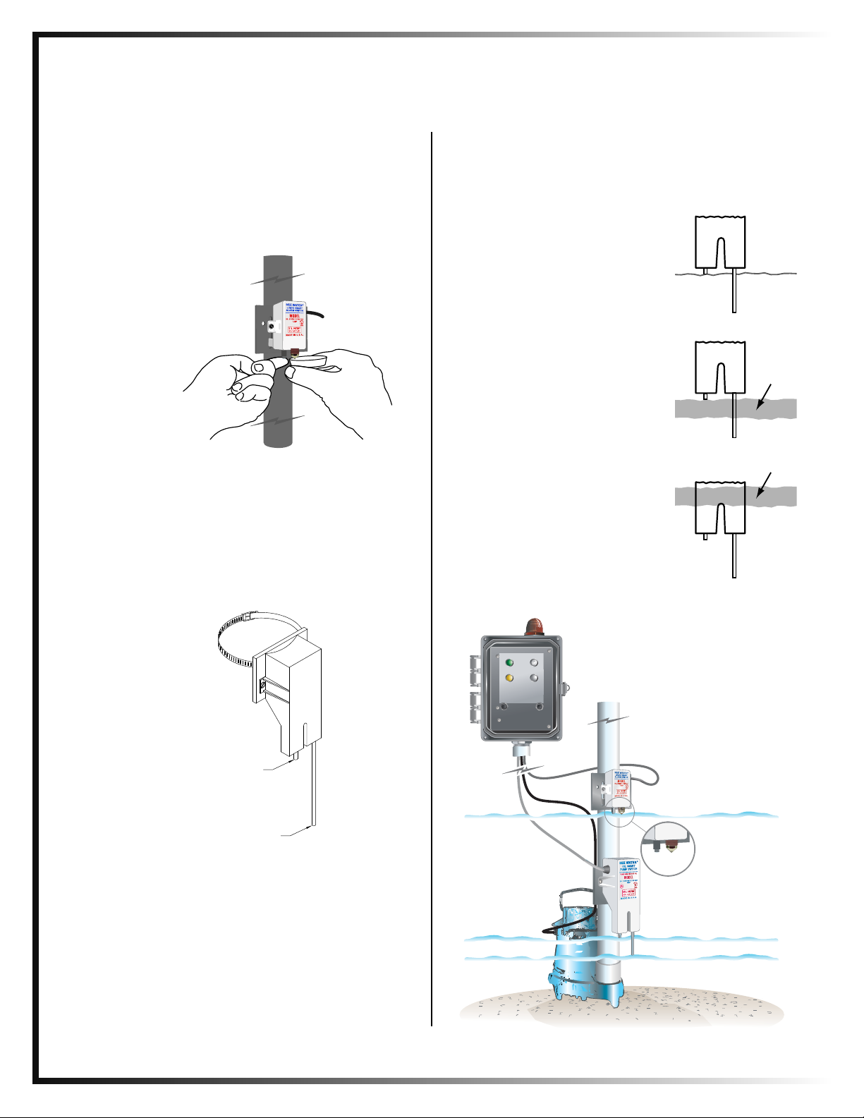
Components Installation:
I. The Oil Smart Pump Switch and Liquid Smart
Alarm Sensor shall be mounted in a clean
environment, clear of mud and all metallic
debris.
II. The switches shall be installed where the water
intrusion will not directly contact or splash the
white plastic case.
III. Mud or other conductive materials left on the
body of the switches will hamper its operation;
clean the switch with rubbing alcohol prior to
initital installation.
IV. Mount with enclosed mounting brackets. Note:
Keep sensors at least 2” clear of any metallic
material.
1. All installations must be in accordance with the National Electrical
Code, and any other applicable state and local electrical
requirements.
Sing
#
www.seewaterinc.com
or www.oilsmart.org
951.487.8073 • 888.733.9283
Email: info@seewaterinc.com
121 North Dillon Street • San Jacinto, CA 92583
P.O. Box 1269 • San Jacinto, CA 92581
Fail-Safe Technology since 1995.
©Copyright 2009 See Water, Inc. All Rights Reserved.
Installation and Operator's Manual
Oil Smart® Simplex Panel (Model #OSSIM-30)
Testing:
• Liquid Smart® Alarm Sensor: Fill small cup
supplied with oil. Submerge only the plastic lens
(optic sensor) into oil, the alarm will activate
showing oil present (yellow light). Now touch
finger to the exposed stainless steel sensor, the
alarm will show water present (white light) will
turn on.
• Oil Smart® Switch: Place the HOA switch on
control panel in the automatic position. Place your
thumb on the short sensor of Oil Smart® Pump
Switch and the pump will turn on. While touching
the short sensor, touch the long sensor “off” with
your fingers. Remove your thumb from on sensor
and begin to move your fingers down the off
sensor. Remove your fingers from off sensor and
the pump will turn off.
Operation:
Normal Condition (Water Only)
The short sensor probe turns the pump
"on" and the long sensor probe turns
the pump "off". When the short sensor
is in contact with water, the pump will
continue to cycle "on and off" until the
short sensor detects oil.
Oil Present Condition
The pump will not cycle if oil is in
contact with the short sensor.
High Water (Oil Present Condition)
If additional water enters the basin, it
will cause the oil layer to rise above
the short sensor, resulting in the pump
cycling.
"OFF"
"ON"
WATER
WATER
OIL
LAYER
WATER
OIL
LAYER
PUMP ON MANUAL OFF AUTO
WATER OIL
SILENCE TEST
SSEEEE
WWAATTEERR,,IInncc..
Oil Smart
®
Alarm System
©Copyright 2009 See Water, Inc. All Rights Reserved.
Oil Smart and Liquid Smart Maintenance:
Plastic Switch case must be kept clean. Free of: rust,
mud, soap, etc. If switch is submerged in water
during initial installation, switch must be cleaned.
Clean with a rag and household Alcohol or
kerosene. Consistent inspection and preventive
maintenance ensures longevity and proper operation
of components. It is recommended to develop
a schedule to keep the white plastic case clean.
Liquid Smart Switch
Oil Smart Switch
High Liquid Level
On
Off
Note: Off sensor needs to be a minimum
of 2" above the impeller of the pump

See Water
Alarm
Circuit Board
Terminal 1 Terminal 2
Motor
Starter
Blue
Red
White
Green
X
(120V) L
N
Water
Common
Oil
High Liquid
Terminal 1 (Alarm) Terminal 2 (Pump Control)
Liquid Smart 120V Dry Contacts
For 120V Power Supply
For 240V Power Supply
Setup for 120V *
(For 240V,
Remove Jumper)
L1 N* T1 T2
P N
Brown
Black
White
Power Supply Pump Oil Smart Switch
120V
P P N T1 T2
P N
Power Supply Pump Oil Smart Switch
120V
Brown
Black
White
©Copyright 2009 See Water, Inc. All Rights Reserved.
Data:
• Pollution degree 2
• Installation category II
• Altitude 2000m
• Humidity up to 5% to 95%
Warranty:
See Water® Inc. warrants that the See Water Control Panel will be free from defects in material and
workmanship for a period beginning as of the date of purchase for two (2) years. Replacement of the panel
and/or components is only at the sole discretion of See Water Inc. This warranty is valid only when the
product is installed in strict compliance with the manufacturer's installation instructions. See Water, Inc.
will in no way be responsible for the reliability of any pump that is connected to or operates with See
Water, Inc. products. See Water, Inc. will replace the panel when it is returned to See Water's factory,
postage prepaid with proof of original purchase included. It is imperative that in no way, can any
components/parts be removed from the control panel during installation. Any alterations/additions/changes
to the panel will result in a void warranty. Failure to properly install and test this product can result in
personal injury or equipment malfunction.
©Copyright 2009 See Water, Inc. All Rights Reserved.
Problem Possible Cause Solution
Pump Control does not activate The Oil Smart Switch will not Make sure phase and neutral are
the pump. Pump does not run. function with incorrect polarity. not reversed.
Loose connection in control panel. Confirm all connections are tight
or electrical system. and secure.
Non-Conductive Water Test pump switch with fingers per
(Highly Filtered Water) the instructions (See Page 2)
Defective Control Replace Control
Pump Control is not operating Problem with electrical system Check electrical circuits for
properly; not consistant or common neutrals;
staying on. may cause switch to not function
correctly.
Control Panel Wiring Problems Do not run DC conductors
through same conduit as AC
conductors. Circulating current
can cause problems.
Control is not clean of conductive White plastic case must be kept clean.
material. Clean with alcohol or an oil base
product: kerosene, solvent.
Control is mounted to metallic pipe Keep control (1" to 2") clear of
any metallic material. Mount to pvc
pipe or wrap electrical tape
between pipe and switch.
Float switch attached to pump Float switch must be removed,
secured in manual operation, or
replaced with correct pump.
Defective Control and/or Pump(s) Replace Control and/or Pump(s)
Alarm will not activate Power supply failure Confirm separate 120V power to
circuit board. Can be jumpered
from incoming power on pump
terminal if 120v is available.
Defective Alarm Sensor Replace Alarm Sensor
Loose connection in control panel. Confirm all connections are tight
or electrical system. and secure.
Pump will not turn on or pump is Incorrect match on control panel Confirm correct pump voltage and
not functioning properly. and pump. wires matched to correct control
panel
Loose connection in control panel. Confirm all connections are tight
or electrical system. and secure.
Defective Pump(s) Replace Pump(s)
Oil Smart Control Panel Troubleshooting Guide
Any technical questions on this product should be directed to See Water, Inc at 888-733-9283.
Other See Water Control Panel manuals

See Water
See Water WS Series Setup guide

See Water
See Water WD3P-4-302 Series User manual

See Water
See Water Oil Smart OSSIM-30 User manual

See Water
See Water Oil Smart OSD1P-102 Series User manual

See Water
See Water OSSIM-TP-100 Series User manual

See Water
See Water WS1P-TP-1001 User manual

See Water
See Water Oil Smart OSD3P-30 Series User manual

See Water
See Water OSSIM-TP-30 Series User manual

See Water
See Water WS Series Setup guide

See Water
See Water WS Series User manual


 Installation and operation guide")


