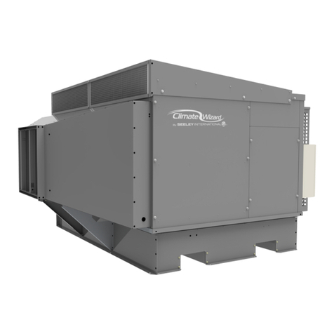
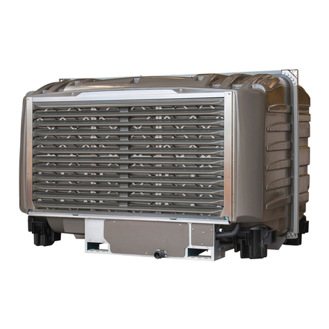
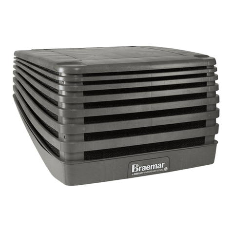
Seeley CW3 User manual

INSTALLATION MANUAL
CW3 MICROCORE INDIRECT
EVAPORATIVE COOLER
Original English Instructions


859741-L CW3 INSTALLATION MANUAL | 1
TABLE OF CONTENTS
WARNING! FAILURE TO INSTALL AND COMMISSION THE PRODUCT IN COMPLIANCE WITH THESE
INSTRUCTIONS, OR FAILURE TO DO THE JOB PROPERLY AND COMPETENTLY, MAY VOID THE
CUSTOMER’S WARRANTY. FURTHER, IT COULD EXPOSE THE INSTALLER AND/OR THE RETAILER TO
SERIOUS LIABILITY.
Index
TABLE OF CONTENTS 1
IMPORTANT SAFETY INSTRUCTIONS 2
COOLER VIEWS 3
EXPLODED VIEW 4
COOLER CONTENTS 6
COOLER INSTALLATION COMPONENTS 6
OPTIONAL COMPONENTS 6
COOLER CONTROLS 6
TRANSPORT 7
MOVING THE COOLER 7
LIFTING THE COOLER 7
UNPACKING THE COOLER 7
INSTALLATION 8
ASSESSMENT OF ROOF STRUCTURE 8
COOLER LOCATION 8
ACCESS FOR SERVICING AND MAINTENANCE 8
MOUNTING / SUPPORT 9
SUPPLY AIR DUCT PREPARATION 9
PREPARING THE TRANSITION 9
PITCHED ROOF INSTALLATION 10
LEVELLING THE SUPPLY DUCT 10
FLASHING THE SUPPLY DUCT 11
WEATHERSEAL ASSEMBLY 11
COMMUNICATION CABLE PREPARATION 12
POWER CABLE PREPARATION 12
COOLER METHOD OF INSTALLATION 13
PREPARING TO LIFT THE COOLER 13
LIFTING THE COOLER 13
COMMUNICATION CABLE INSTALLATION 15
ELECTRICAL REQUIREMENTS 16
ELECTRICAL SUPPLY INSTALLATION 16
MOTOR LOCKED-ROTOR PROTECTION 16
ELECTRICAL POWER CABLE 16
CONTROL MODULE WIRING DIAGRAM 16
WATER REQUIREMENTS 17
WATER SUPPLY INSTALLATION 17
WATER SUPPLY PRESSURE REGULATION 17
WATER SUPPLY ISOLATION 17
WATER SUPPLY FILTRATION 17
WATER HAMMER 17
WATER INLET SOLENOID VALVE 17
WATER DRAIN INSTALLATION 18
COOLER CONTROL COMPONENTS 19
WATER MANAGEMENT SYSTEM 19
COOLER CONTROL OPTIONS 20
MAGIQTOUCH CONTROLS 20
GROUP INSTALLATIONS 20
COMMISSIONING 21
INSTALLATION CHECKLIST 21
MAGIQTOUCH SERVICE MENU 22
WATER MANAGEMENT SYSTEM CHECKS 22
FAN CHECKS 22
COOLING CORE FLUSH 22
CUSTOMER HANDOVER CHECKLIST 22
ADJUSTING COOLER SETTINGS 23
FAULT CODE DESCRIPTIONS 24
TROUBLESHOOTING 25
APPENDIX A: GENERIC ROOF MOUNTING 26
GENERAL NOTES 26
TIMBER TRUSS - 600MM SPACING 28
TIMBER TRUSS - 1200MM SPACING 29
STEEL TRUSS - 600MM SPACING 30
STEEL TRUSS - 1200MM SPACING 31
CONVENTIONAL ROOF FRAMING 32
APPENDIX B: ‘PIECE BY PIECE’ INSTALLATION 34
WARRANTY TERMS (AUSTRALIA) 42
WARRANTY TERMS (USA) 46

2 | 859741-L CW3 INSTALLATION MANUAL
IMPORTANT SAFETY INSTRUCTIONS
READ AND SAVE THESE INSTRUCTIONS
FOR FUTURE REFERENCE.
Means for all pole disconnection must be incorporated in the
If the supply cord is damaged, it must be replaced by the
required:
Min Water Pressure 100kPa (15psi)
Max Water Pressure 800kPa (115psi)
•
•
•
•
Refer to installation section for details
WARNING - TO REDUCE THE RISK OF
FIRE, ELECTRIC SHOCK, OR INJURY TO
PERSONS, OBSERVE THE FOLLOWING:
•
•
•
• Do Not Use This Fan With Any Solid-State Speed Control
FOR AUSTRALIAN BUSHFIRE PRONE
AREAS
WARNING
be adequately sealed at the roof to prevent gaps greater than
WARNING: This cooler is NOT APPROVED for installation
in any bushre zoned area/property (BAL-12.5 to BAL-FZ).
EMPLOYER AND EMPLOYEE
RESPONSIBILITIES
The installation and maintenance of evaporative coolers at
height has the potential to create Occupational Health and
legislation, such as Acts, Regulations, approved Codes of
INSTALLER AND MAINTENANCE
CONTRACTORS - RISK ASSESSMENT
This should be considered in terms of:
• What are the chances of an incident happening?
• What could the possible consequence be?
• What can you do to reduce, or better still, completely get rid of
SOME POINTS TO CONSIDER
•
areas?
•
• What condition is the roof in? Should the trusses, underside
•
•
• Are all ladders, tools and equipment suitable in good
condition?
•
at the top? Is the top of the ladder clear of electricity supply
cables?
• Is there a roof anchor to attach a harness and lanyard to? If
so, instruction should be issued for the use of an approved
• Are all tools and materials being used, prevented from
slipping and falling onto a person at ground level? Is the area
•
surfaces?
•
•
alcohol?
•
lines?
OTHER IMPORTANT REQUIREMENTS
•
•
•
•
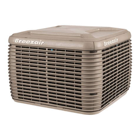
859741-L CW3 INSTALLATION MANUAL | 3
COOLER VIEWS
ILL2679-A
ILL2676-A
TOP ISO
ILL2680-A
ILL2677-A ILL2675-A
FRONT SIDE
SERVICES UNDERSIDE
1160mm
1160mm
1020mm
supply duct
Inlet
Inlet
Drain
Drain
CW logo location
212mm
212mm
ILL2678-A
Dimensions are in mm (inches in brackets).

4 | 859741-L CW3 INSTALLATION MANUAL
EXPLODED VIEW
ILL2982-B
ITEM PART NO. DESCRIPTION QTY
1562162 TANK 1
2562391 CLIP PANEL SIDE 8
3 CLIP PANEL TOP
4562179 PANEL SIDE
5855879 8
6562063 LID GRILLE EXHAUST 1
7562223 LID SCREW GRILLE 8
8 STRAP TRANSITION
10 122328 DROPPER TRANSITION ASSY 1
11 639381 T-WASHER
12 PLENUM INNER 1
13 PLENUM OUTER
21 122175RP MOTOR ASSY 1PH INVERTER DRIVE 1
22 122182RP MOTOR ASSY 1PH INVERTER DRIVE 1
23 562308 RING MOTOR LOCK 2
24 VENTURI SUPPLY 1
25 FAN SUPPLY 1
26 562186 MOUNT MOTOR SUPPLY 1
27 562056 VENTURI EXHAUST 1
28 FAN EXHAUST 1
INDEX PART NO. DESCRIPTION QTY
29 CAP FAN EXHAUST 1
30 863832 PLUG VENTURI 1
31 863665 STRAPS RETENTION MANIFOLD 16
32 CHLORINATOR LARGE ASSY 1
33 COVER CHLORINATOR MOUNT 1
34 FITTING ELBOW AIR-BREAK 1
36 1
40 833835 1
639392 BRACKET PROBE 1
41 PUMP 230/50 TWIN OUTLET 50Hz 2
41 PUMP 230/50 TWIN OUTLET 60Hz 2
48 122311RP DRAIN VALVE ASSY 12V MFG 1
49 1
52A 861593 1
53A ADAPTOR DRAIN 32-20MM 1
53 117928RP CONTROL ASSY 1
54 862758 ELECTRONICS MOUNT PLATE 1
55 862757 ELECTRONICS SPLASH COVER 1

859741-L CW3 INSTALLATION MANUAL | 5
EXPLODED VIEW
ILL2982-A
INDEX PART NO. DESCRIPTION QTY
14, 15,
17, 18 122199RP ENCAPSULATION INDIRECT & DIRECT RIGHT
14, 15,
17, 18 122205RP ENCAPSULATION INDIRECT & DIRECT LEFT
14A CHILLCEL 263*665*35 8
19 SPREADER ELBOW CLIP 16
20 863208 O RING BS112 16
ILL3892
INDEX PART NO. DESCRIPTION QTY
60 862761 TUBE SOLENOID CW3 1
61 863760 COVER SOLENOID CW3 1
62 859713 SOLENOID VALVE SS 12VDC 1
63 865615 1
64 815979 1
65 861586 3
66 COMPRESSION OLIVE KIT 1
67 BRASS TUBE 1
68 815978 WASHER RUBBER 1
68
65
66
61
60
62
64
63
65
67

6 | 859741-L CW3 INSTALLATION MANUAL
COOLER CONTENTS
COOLER INSTALLATION COMPONENTS
control items and other components that are required for
OPTIONAL COMPONENTS
ITEM 1. ITEM 2
ITEM 9 ITEM 10 ITEM 11
ITEM 12 ITEM 13
ITEM 3 ITEM 4
ITEM 6 ITEM 7 ITEM 8
ILL3813-A
ITEM 5
ITEM 1 ITEM 2
ILL -A3814
ILL2425-B
ILL3813-A
COOLER CONTROLS
ITEM 1 ITEM 2 ITEM 3 ITEM 4
ITEM 5 ITEM 6 ITEM 7 ITEM 8
ITEM 9 ITEM 10 ITEM 11
ITEM 12 ITEM 13
ITEM 1 ITEM 2
ITEM PART NO. DESCRIPTION QTY
1856162 1
2833880 1
3 Instructions - Installation 1
4122311RP Drain Valve Assy 12V 1
5 1
6 Supply Duct Height Gauge 1
7583020 Grommet for Dropper 1
8639381 T-Washer
9101713 Adapter Drain Fitting Assembly 1
10 123097 Kit Solenoid Valve & Covers 1
11 122328 Supply Duct Transition Assembly 1
12 875392
20
13 560359 1
ITEM PART NO. DESCRIPTION
1
2A
2B
Roofstand 0-10O
ITEM 12

859741-L CW3 INSTALLATION MANUAL | 7
TRANSPORT
ILL2773-B
Remove the top horizontal timber support members and
UNPACKING THE COOLER
control items and other components that are required for
ILL2772-A
ILL2772-A
ILL2773-B
MOVING THE COOLER
ILL2970-B
ILL2970-B
1 2 3
LIFTING THE COOLER
pallet
It is recommended to use a spreader bar on the straps or slings
beneath the lifting straps to avoid any damage to the cabinet

8 | 859741-L CW3 INSTALLATION MANUAL
INSTALLATION
COOLER LOCATION
The ideal location for the cooler is in a central position on the
Ensure location is a minimum of:
•
•
•
•
•
ILL2962-A
•
ILL3815-A
ILL -A3815
350 (14")mm
WEATHERSEAL SWING
CLEARANCE
600mm 2( 4")
WALL
CLEARANCE
350mm (14”)
WEATHERSEAL
OPENING
CLEARANCE
600mm (24”)
WALL
CLEARANCE
ACCESS FOR SERVICING AND
MAINTENANCE
access for installation and future maintenance and servicing
• Which has clear access to and around the cooler
•
•
•
cooler and service technicians
Required clearances around the cooler for future maintenance
ILL2987-A
equipment or additional labour involved in accessing the cooler
Note!
ASSESSMENT OF ROOF STRUCTURE
THE COOLER REQUIRES AN ADEQUATE ROOF
STRUCTURE TO BEAR THE LOAD OF ITS OPERATING
WEIGHT. IT IS LIKELY THAT MOST RESIDENTIAL
STRUCTURES WILL REQUIRE REINFORCEMENT.
Engineering designs of roofs, including the supporting
It is the installers responsibility to verify the integrity of the roof
of the structurally engineered roof mounting schemes provided
If these generic schemes are not applicable to the customer
installer has any doubt in regards to the structural integrity or
condition of the customer installation, then a structural engineer
SHIPPING OPERATING
WEIGHT
clearances;
•
•

859741-L CW3 INSTALLATION MANUAL | 9
INSTALLATION
SUPPLY AIR DUCT PREPARATION
ILL2774-A
ILL1646-A
PREPARING THE TRANSITION
ILL2775-A
Fit the transition onto the supply duct, ensuring that it is
ILL2776-A
MOUNTING / SUPPORT
Roofstands, accommodating 0-10 roof pitches, are available for
ILL3368-A
COOLER
FRONT COOLER
SIDE

10 | 859741-L CW3 INSTALLATION MANUAL
INSTALLATION
PITCHED ROOF INSTALLATION
ILL2778-A
The following method of height-setting is only applicable
for roof angles between 15 and 30 degrees.
ILL2977-A
ILL2978-A
IT IS IMPORTANT THAT THE COOLER IS LEVEL IN ALL
DIRECTIONS. COOLERS WHICH ARE NOT LEVEL MAY
CAUSE REDUCED WATER PUMP FLOW RATES AND/OR
INCREASED DRAIN WATER OVERFLOW.
ILL2980-A
Adjust the position of the supply duct such that the equal angle
LEVELLING THE SUPPLY DUCT
Once level, secure the supply duct to the roof structure using
roong screws
DO NOT USE THE PROVIDED TEK SCREWS – THESE ARE
FOR LATER USE ELSEWHERE.
The installer must ensure the dropper is secured adequately
ILL3916-A
used to accurately set the height of the supply duct above the

859741-L CW3 INSTALLATION MANUAL | 11
INSTALLATION
T-WASHER FITMENT
ILL2782-A
ILL2783-A
FLASHING THE SUPPLY DUCT
This must be completed
before tting the cooler.
DO NOT USE THE PROVIDED TEK SCREWS – THESE ARE
FOR LATER USE ELSEWHERE.
WEATHERSEAL ASSEMBLY
ILL2964-A
Important!

12 | 859741-L CW3 INSTALLATION MANUAL
INSTALLATION
COMMUNICATION CABLE PREPARATION
routed through the transition corner recess prior to the cooler
ILL3116-A
ILL3029-A
Pass the non-taped end of the control cable up into the supply
the inside of the supply duct, the free end needs to be located
POWER CABLE PREPARATION
FEED POWER CABLE
THROUGH REAR
ACCESS HOLE

859741-L CW3 INSTALLATION MANUAL | 13
INSTALLATION
ILL2785-A
ILL3027-A
ILL3028-A
Important!
LIFTING THE COOLER
Place the slings underneath the cooler and through the
PREPARING TO LIFT THE COOLER
IT IS THE RESPONSIBILITY OF THE RIGGER TO
DETERMINE THE APPROPRIATE METHOD AND
EQUIPMENT FOR LIFTING THE COOLER.
DO NOT LIFT USING ANY CABINET FEATURES,
ALTERNATE SLING LOCATIONS OR BY RETRO-FITTING
LIFTING LUGS.
The cabinet may be damaged and/or lift safety may be
DO NOT ATTEMPT TO LIFT THE COOLER WITHOUT THE
FOAM SUPPORTING BLOCKS.
If they are missing or damaged, contact the dealer and/or resort
DO NOT ATTEMPT TO LIFT THE COOLER ON THE PALLET.
Before the cooler is lifted:
•
•
•
•
•
ILL3026-A
COOLER METHOD OF INSTALLATION
1. Installation via crane (preferred) – cooler is lifted from its
2. Piece by piece assembly – cooler is disassembled on the
installation, be sure to consider regulations, location, access

14 | 859741-L CW3 INSTALLATION MANUAL
INSTALLATION
ILL2786-A
WARNING! BE EXTREMELY CAREFUL NOT TO TRAP
HANDS IN BETWEEN THE COOLER AND TRANSITION.
DO NOT POSITION ANY PART OF YOUR BODY
UNDERNEATH THE COOLER WHILE IT IS SUSPENDED BY
CRANE.
BE EXTREMELY CAREFUL NOT TO DAMAGE THE
TRANSITION STRAPS, COMMUNICATION OR MAINS
POWER CABLES.
ILL3030-A
the inside of the supply duct, guide the free end into the corner
ILL3036-B
the supply duct transition as the cooler is being
ILL3125-A

859741-L CW3 INSTALLATION MANUAL | 15
COMMUNICATION CABLE INSTALLATION
The communications cable should be hanging loose on the
INSTALLATION
ILL3029-B
Feed the communication cable through the rear access hole in
Route the communication cable across the cable tray on the
ILL3109-A
ILL3110-A
UNDERSIDE VIEW
TOP VIEW
ILL3112-A
UNDERSIDE VIEW
ISOLATION
SWITCH
ILL3111-D
WALL CONTROL CABLE
DRAIN VALVE CABLE
INSTALLATION
CONNECTIONS
ILL3111-D

16 | 859741-L CW3 INSTALLATION MANUAL
ELECTRICAL REQUIREMENTS
ILL2681-D
PUMP
LEFT
(INDIRECT)
PUMP
RIGHT
(DIRECT)
MOTOR
BOTTOM
POWER
ON / OFF
FUSE
250V, 10A
F2
MODBUS
TERMINATING
RESISTOR
SUPPLY
MOTOR (BOTTOM)
SIGNAL
SUPPLY
MOTOR
EXHAUST
MOTOR (TOP)
SIGNAL
EXHAUST
MOTOR
MOTOR
TOP
COMMS
SOLENOID
WATER
PROBE
DRAIN
CHLORINATOR
COMMS
ILL2681-D
CONTROL MODULE WIRING DIAGRAMELECTRICAL SUPPLY INSTALLATION
INSTALLATION OF THE COOLER MUST CONFORM
TO LOCAL ELECTRICAL RULES, REGULATIONS AND
STANDARDS.
It is a requirement of Seeley International that all coolers be
IMPORTANT!
Electrical Supply Specication (IEC):
220-240V / 50Hz / 1~ / 7.0A
Electrical Supply Specication (USA):
220-240V / 60Hz / 1~ / 7A FLA / 15A MOPD
MOTOR LOCKED-ROTOR PROTECTION
WARNING!
ILL2983-A
ELECTRICAL POWER CABLE
WARNING!
NOTE!
AUSTRALIA ONLY
REST OF WORLD
ILL3102-A
Important! Ensure the mains cable is not submerged
or touching the water in the tank at any point along the
cable length. Make use of the cable restraints. Cable tie to
existing looms if necessary.

859741-L CW3 INSTALLATION MANUAL | 17
WATER REQUIREMENTS
WATER INLET SOLENOID VALVE
WATER SUPPLY INSTALLATION
INSTALLATION OF THE WATER SUPPLY MUST CONFORM
TO LOCAL PLUMBING RULES, REGULATIONS AND
STANDARDS.
Water Connections:
Water Supply:
Water Supply Temperature:
Water Supply Salinity:
WATER SUPPLY PRESSURE REGULATION
Important!
Important!
ºº
is recommended that a suitable pressure relief valve is also
WATER SUPPLY ISOLATION
freezing conditions, to avoid possible damage to the cooler
WATER SUPPLY FILTRATION
Important!
lodge in the inlet solenoid valve, preventing it from functioning
hardness, acidity or chemical contaminants, then additional
WATER HAMMER
ILL3902
ILL3111-D
SOLENOID

18 | 859741-L CW3 INSTALLATION MANUAL
ILL2791-A
Important!
Drain Connection:
Drain Flow Rate:
Important! Water drained from the drain valve is high in salinity
Important!
points, and/or incorporating traps shall use a tundish or similar
WATER REQUIREMENTS
WATER DRAIN INSTALLATION
INSTALLATION OF THE WATER DRAIN MUST CONFORM
TO LOCAL PLUMBING RULES, REGULATIONS AND
STANDARDS.
ILL3111-D
DRAIN
Table of contents
Other Seeley Accessories manuals

Seeley
Seeley Climate Wizard CW-P15 Owner's manual

Seeley
Seeley Breezair EXS User manual

Seeley
Seeley Breezair EXT User manual

Seeley
Seeley LCQ User manual

Seeley
Seeley Convair CTA250 User manual

Seeley
Seeley Climate Wizard CW-80 User manual

Seeley
Seeley Aira AL Series User manual

Seeley
Seeley Climate Wizard CW-H10 User manual
Popular Accessories manuals by other brands

DirecTV
DirecTV Wireless Cinema Connection Kit user guide

HB Products
HB Products HBIB Installation and Calibration Manual

Black & Decker
Black & Decker SF100 instruction manual

Air Creation
Air Creation IXess 13 Maintenance manual

Vivanco
Vivanco PB 2000 / 33949 user manual

DAVIS
DAVIS Solar Power Kit installation manual