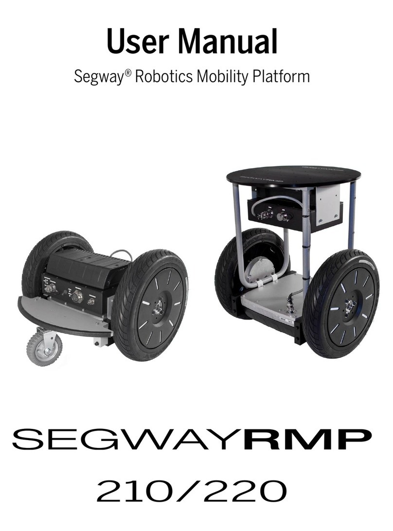
Segway RMP Lite 220 User manual

1
User Manual
Segway RMP
(Robot Mobile Platform)
RMP Lite 220
©2021 Segway-Ninebot All Rights Reserved

2
General Information
The Robot Mobile Platform(RMP)provides general or integrated
robot chassis solutions for enterprises or third-party developers,
with versatility, durability and performance in mind. RMP Lite 220
(hereinafter referred to as RMP) is a mobile robot chassis product
designed for indoor and outdoor distribution, inspection, service,
cleaning, and warehousing AGV. It is designed to provide
large-scale and customized services for companies in the robotics
field such as special application robots.
Main features of RMP:
• Hardware: compact and equipped with a large-capacity
battery;
• Software: compatible with ROS and Isaac operating systems;
• Hardware modular design, interface with software SDK,
support secondary development or customized service;
• Support extension kits include: light strips, sensor mounting
rods, and so on.

3
Safety
Incorrect use of RMP may cause loss of control, collision or fall of
the RMP, resulting in property damage, personal injury, and even
death. Therefore, in order to reduce risks and avoid injury, please
read and follow all instructions and warnings in this manual.
The following secure messaging conventions are used in this
document:
Warning!
Warns you of operations that may cause serious
injury or even death
Attention!
Warns you of operations that may cause minor or
moderate injuries
Please note
Indicates important information, but does not
involve personal injury
Warning!
Please keep RMP out of the reach of children and pets.
Accidental movement of RMP may cause injury or even death.
Please do not sit, stand or ride on the RMP. Doing so may cause
injury or even death.
Please do not control RMP to hit people or animals. Collision may
cause injury or even death.

4
When RMP is running, remind people nearby at all times.
Accidental collision with RMP may cause injury or even death.
Avoid power failure on slopes. RMP cannot maintain its position
on the slope when the power is off. The power off will cause RMP
to slide, which may cause injury or even death.
RMP can accelerate quickly. It is recommended that using low
speed to practice until the you are familiar with controlling RMP.
Accidental movement of RMP may cause injury or even death.
Please do not try to disassemble the battery, it may cause electric
shock, burns or even fire. Attempting to open the battery case will
damage the battery case, release toxic and harmful substances,
and also render the battery unusable.
The same with all rechargeable batteries, please do not charge
near flammable materials, which may cause a fire.
If the battery case is damaged or the battery emits peculiar smell,
smoke, overheating or leakage, please do not continue to use the
battery and do not contact with any substances leaking from the
battery to avoid poisoning.
Strictly observe and follow all safety information on the warning
label on the battery. Failure to do so may result in injury or even
death.

5
Please do not use cables that have been seriously worn or
damaged, which may shock yourself or damage the RMP.
Attention!
The performance parameters should be set correctly and
carefully. RMP follows the commands issued to it, users are
responsible for implementing correct and safe performance
parameters.
Do not charge the battery may cause permanent damage to the
battery.
Only can use the charger that is provided with RMP Lite 220 to
charge the batter.
Before operating RMP, please be sure to read the user’s manual
and be familiar with the operation of RMP and various
precautions.
Please Note
If the user modifies the chassis without communication with
Segway-Ninebot and causes an accident, Segway-Ninebot
does not assume any responsibility.

6
Table Of Contents
1 Product introduction ............................................................................................................7
1.1Product diagram ........................................................................................................ 7
1.2 Component description ............................................................................................ 8
1.3 Remote control ......................................................................................................... 9
1.3.1 Remote control diagram ................................................................................. 9
1.3.2 Receiver pairing ............................................................................................10
1.3.3 Remote control control car instructions ........................................................ 11
1.3.4 Upper computer control car instructions ...................................................... 12
2 Software introduction ........................................................................................................16
2.1 Documents provided to users ............................................................................... 166
2.2 Interface function introduction .............................................................................. 166
2.2.1 C/C++ Interface introduction .......................................................................166
2.2.2 ROS Interface introduction—SmartCar ........................................................20
2.2.3 Error code information table ........................................................................ 23
3 Firmware upgrade and version upgrade .......................................................................... 25
3.1 Firmware upgrade .................................................................................................. 25
3.2 Version upgrade .....................................................................................................28
Appendix I System parameters and mode switching logic ...................................................31
Appendix II Connector welding instructions ........................................................................ 34
Appendix III Connector pin angle definition instructions ...................................................... 37
Appendix IV C/C++ APIReference documents .................................................................... 37

7
1 Product introduction
1.1Product diagram
Figure 1
Figure 2

8
1.2 Component description
Table 1
No.
Component name
Description
1
Power button
On:Hold down, when power button and indicator light are
always on and accompanied by a beep, chassis boots
successfully. At this time, the chassis is in lock mode, and the
indicator light is steady yellow.
Off:Hold down until the prompt sound starts,release the
button,chassis shut down successfully. At this time, power
button and indicator light are always off.
2
Indicator light
Colors and status of the indicator light represent different
modes of the product.
3
Driving wheel
11 inch high adhesion pneumatic tire with good shock
absorption and design with drainage tank.
4
Universal wheel
Super Artificial rubber, lightweight and shock absorption.
5
Mounting hole
Use to install upper equipment.
6
Battery
Power supply to chassis and upper system.
7
Emergency stop
button
Use to switch the chassis to emergency stop mode in an
emergency.
8
Charging port
Connect the charger to charge the device.
9
Battery lock
Used to fix the battery, need to use the matching key to open.
10
Upper computer
power supply port
It supplies power to the upper computer, with a maximum
current of 10A.
11
Electric control box
Use to install circuit module to control the chassis.
12
Upper computer
power supply port
It supplies power to the upper computer.

9
1.3 Remote control
1.3.1 Remote control diagram
Figure 3
*The forward or backward of the remote control input (throttle or
rudder) can be realized by flipping the enable switch under the T8FB.
Figure 4
Coach interface / Simulator interface /
Firmware upgrade interface
Battery cover

10
*The alarm voltage of the remote control is adaptive to 2S, 3S, 4S
lithium batteries and 4 NI-MH batteries. That is, if T8FB is powered
by 2S, 3S, 4S lithium batteries or 4 NI-HM batteries, after connecting
the battery, T8FB will automatically set the low voltage alarm value
according to the battery type.
1.3.2 Receiver pairing
Each transmitter has an independent ID code. Before starting to
use the device, receiver must pair the code with the transmitter. After
pairing the code, the ID code is stored in the receiver, and there is no
need to pair it again, unless the receiver is used with another
transmitter. When you have a new receiver, you must pair the code
again, otherwise the receiver will not work normally.
( 1 ) Place the remote control and receiver horizontally with a
spacing of about 50cm;
(2)Turn on the power switch of the remote control to supply
power to the receiver, and the receiver’s LED light starts to flash
slowly;
(3)Press the pairing code button (ID SET)on the side of the
receiver for more than 1 second, the LED light starts to flash quickly,
that means the code is being paired, and the receiver will look for the

11
nearest remote control to pair the code;
(4)When the receiver’s LED light stops flashing, it means that
pairing the code is completed. If the receiver ’ s LED light flashes
slowly, it means that pairing the code has failed, the code needs to
be paired again.
1.3.3 Remote control control car instructions
(1)Turn on the RMP chassis: press the RMP power button;
Note: Please check the RMP status. Press and hold until the
buzzer sounds and there is no continuous beeping, the indicator light
is steady yellow.
(2)Turn on the remote control: push up the power switch of the
remote control;
Note: ensure that the remote control is not in the emergency stop
state and enters the enable state.That is, the emergency stop switch
is not at the bottom, and the enable switch is dialed from the top to
the bottom.
(3)At this time RMP is in Normal mode , see the table below for
specific operations:

12
Table 2: Car control and remote control operation
Car control
Remote control operation
Turn left/ right
Rudder lever
Move
forward/backward
Throttle lever
Emergency stop/ exit
emergency stop
Emergency stop switch:At the top: exit the emergency stop;
At the bottom: start the emergency stop
Adjust the maximum
value of angular
velocity
Maximum angular velocity adjustment knob: Turn left: the
maximum angular velocity decreases, Turn right:
increases.
Adjust the maximum
value of linear velocity
Maximum linear velocity adjustment knob: Turn left: the
maximum linear velocity decreases, Turn right: increases.
Enable/Disable
Turn the enable switch from the top to the bottom: Enable;
Turn the enable switch from the bottom to the top: Disable.
1.3.4 Upper computer control car instructions
The host computer is the control computer, which can directly
issue control commands and display various information changes on
the screen. The upper computer controls the lower computer and
provides some necessary operating environment for the lower
computer, and extends the man-machine control or demonstration
function that the lower computer can provide. The upper computer
has the characteristics of leading management, coordinating
resources, monitoring agency, and controlling RMP.
(1)Turn on the RMP chassis: press the RMP power button;

13
Note 1 : Please check the RMP status. Press and hold until the
buzzer sounds and there is no continuous beeping, the indicator light
is steady yellow.
Note 2: When the upper computer controls the car, the remote
control cannot be turned on. Or if the remote control is turned on,
turn its enable switch upward.
(2)Ensure that the RMP serial line or CAN line is connected to
the upper computer;
( 3 ) In the upper computer, give permissions to “ /sdcard/
segway/ hardware_log/”folder, otherwise it will fail to create a new
log file; give permissions to all files in the “/catkin_ws/ src/ RosCode/
segwayrmp/ lib/”directory(no need to reset after first setup) :
`cd /sdcard/segway/hardware_log`
`sudo chmod 777 /sdcard/segway/hardware_log/`
`cd $PRO_HOME$/catkin_ws/src/RosCode/segwayrmp/lib/`
`sudo chmod 777 *
(4)In ”catkin_ws/ src/ RosCode/ segwayrmp/ Cmakelists.txt”
file , according to the upper computer in x86_ 64 or arm platform,
select the compilation option,as shown below when compiling in
x86_64 platform, comment out “ libctrl_arm64-v8a.so ” with the
symbol “#”, (no need to reset after first setup):

14
`target_link_libraries(SmartCar`
`${catkin_LIBRARIES}`
`#${PROJECT_SOURCE_DIR}/lib/libctrl_arm64-v8a.so //in
x86_64 platform , comment out this line , in arm platform, do not
comment out this line`
`${PROJECT_SOURCE_DIR}/lib/libctrl_x86_64.so //in arm
platform,comment out this line,in x86_64 platform, do not comment
out this line`
(5)Enter ROS system,run the following command to compile
the “segway_msgs” package message.
cd catkin_ws
catkin_make
-DCATKIN_WHITELIST_PACKAGES='segway_msgs'
(6)Enter ROS system,run the following command to compile
the “segwayrmp” package message.
cd catkin_ws
catkin_make
-DCATKIN_WHITELIST_PACKAGES='segwayrmp'
(7)Control car in ROS system:
1)Create a new terminal,run the following command:
cd catkin_ws

15
roscore
2 ) Create a new terminal, run the following command, run
SmarCar node:
cd catkin_ws
source devel/setup.bash
rosrun segwayrmp SmartCar
3 )Create a new terminal , run the following command, run
routine test node:
cd catkin_ws
source devel/setup.bash
rosrun segwayrmp ChassisResponseTest

16
2 Software introduction
This chapter introduces relevant documents, software interface
functions and fault code information provided by RMP.
2.1 Documents provided to users
Table 3 Documents provided
Document
Function
Libctrl_x86_64.so
Provide C/C++ chassis-related
interfaces in x86 platform
Libctrl_arm64-v8a.so
Provide C/C++ chassis-related
interfaces in arm platform
Comm_ctrl_navigation.h
C/C++ API interface header file
ROSpackage
Provide chassis control ROS
nodes
2.2 Interface function introduction
2.2.1 C/C++ Interface introduction
Table 4 callback data type
Callback type
Callback No.
Function description
Data structure
Chassis_Data_Speed
1
Chassis speed
information
typedef struct{
int16_t l_speed;

17
int16_t r_speed;
int16_t car_speed;
int16_t turn_speed;
}chassis_speed_data_
t;
Chassis_Data_Ticks
2
Chassis encoder
information
typedef struct{
int32_t l_ticks;
int32_t r_ticks;
}motor_ticks_t;
Chassis_Data_Odom_
Pose_xy
3
Odom pose
information
typedef struct{
float pos_x;
float pos_y;
}odom_pos_xy_t;
Chassis_Data_Odom_
Euler_xy
4
Odom Euler
x/y axis information
typedef struct{
float euler_x;
float euler_y;
}odom_euler_xy_t;
Chassis_Data_Odom_
Euler_z
5
Odom Euler
Z axis information
typedef struct{
float euler_z;
}odom_euler_z_t;
Chassis_Data_Odom_
Linevel_xy
6
Odom speed
x/y axis information
typedef struct{
float vel_line_x;
float vel_line_y;
}odom_vel_line_xy_t;
Chassis_Data_Imu_G
yr
7
Gyroscope data
typedef struct{
int16_t gyr[3];
}imu_gyr_original_dat
a_;
Chassis_Data_Imu_Ac
c
8
Accelerometer
data
typedef struct{
int16_t acc[3];
}imu_acc_original_dat
a_;
Note 1:Odomdata:The default heading angle is 0 degrees at start up.
Note 2:IMU(gyroscope and accelerometer)data:the carrier coordinate
systemXYZ corresponds to the right front up.
Table 5 event definition
Event type
Event No.
Function description
ChassisBootReadyEvent
1
Chassis central control

18
board start up completed
PadPowerOffEvent
2
Chassis shutdown
OnEmergeStopEvent
3
Enter emergency stop
OutEmergeStopEvent
4
Exit emergency stop
OnLockedRotorProtectEvent
5
Locked rotor event occurs
OutLockedRotorProtectEvent
6
Locked rotor event
removes
OnLostCtrlProtectEvent
7
Lost control event occurs
OutLostCtrlProtectEvent
8
Lost control event removes
CalibrateGyroSuccess
9
Calibrate the gyroscope
success
CalibrateGyroFail
10
Calibrate the gyroscope fail
CalibratePasheCurrentSuccess
11
Calibrate phase current
success
CalibratePasheCurrentFail
12
Calibrate phase current fail
Table 6 get/set interface
Interface name
Interface description
get_err_state
Get the error code of the upper computer/central control
board/motor board/battery
get_bat_soc
Get the percentage of battery remaining
get_bat_charging
Get battery charge status(1: charging; 0: non-charging)
get_bat_mvol
Get battery voltage (unit: millivolt (mV))
get_bat_mcurrent
Get battery current (unit: mA)
get_bat_temp
Get battery temperature (unit: degrees Celsius (˚C))
get_chassis_work_model
Get chassis work model(0:Unload;1:Onload)
get_chassis_load_state
Get chassis load state (0:empty;1:full)
get_chassis_mode
Get chassis mode(0:Locked; 1:Control; 2:Push;
3:Emergency stop; 4:Error)
get_ctrl_cmd_src
Get the current chassis control source (0: remote
control; 1: upper computer)
get_vehicle_meter
Get chassis mileage (unit: meter(m))
get_host_version
Get the upper computer version number
get_chassis_central_version
Get the control board version number
get_chassis_motor_version
Get the motor board version number(Reserved)
get_line_forward_max_vel_fb
Get the forward speed limit value of the chassis (unit:
meter per hour(m/h))
get_line_backward_max_vel_fb
Get the backward speed limit value of the chassis (unit:
meter per hour(m/h))
get_angular_max_vel_fb
Get the limit value of chassis angular velocity (unit:

19
milliradian per second(mrad/s))
getIapTotalProgress
Get IAP progress
iapCentralBoard
Upgrade the central control board IAP
iapMotorBoard
Upgrade the motor board IAP
isHostIapOver
Check if IAP is over
getHostIapResult
Get the IAP result (3: completed; 4: failed: 5:
interrupted; 0: meaningless)
getHostIapErrorCode
Get IAP error code
get_chassis_hang_mode
Get whether the chassis is in the hang mode (0: not in
the hang mode; 1: in the hang mode)
get_charge_mos_ctrl_status
Get charging MOS status (1: charging MOS is on, 0:
MOS is off) (temporarily reserved)
set_cmd_vel
Set the chassis linear velocity and angular velocity (unit:
meter per second(m/s) and radian per second(rad/s))
set_line_forward_max_vel
Set the forward speed limit value of the chassis (unit:
meter per second(m/s))
set_line_backward_max_vel
Set the backward speed limit value of the chassis (unit:
meter per second(m/s))
set_angular_max_vel
Set the limit value of chassis angular velocity (unit: radian
per second(rad/s))
set_enable_ctrl
Set the enable state of the upper computer control car
on the chassis (1: enable; 0 disable)
init_control_ctrl
Chassis initialization interface
exit_control_ctrl
Chassis exit initialization interface
set_smart_car_serial
Set the serial port name used by the upper computer
dynamic library
set_comu_interface
Set the communication interface for communication with
the chassis (0: serial port; 1: CAN)
set_chassis_load_state
Set chassis load state (0:empty;1:full)
set_chassis_poweroff
Set chassis shutdown command
set_remove_push_cmd
Remove chassis push command
setHostIapCanceled
Cancel the upper computer IAP command
set_chassis_hang_mode
Set chassis hang mode(1:enter the hang mode:0:
exit the hang mode)
set_charge_mos_ctrl
Set charging MOS switch(1:turn on MOS, 0: turn off
MOS)(temporarily reserved)
2.2.2 ROS Interface introduction—SmartCar
Table 7 news release
Topic Name
Function
Description
Message Type
Message Type Info
Freque
ncy

20
Bms_fb
Battery related
information
Segway_msgs/ Bms_fb
int16 bat_soc
int16 bat_charging
int32 bat_vol
int32 bat_current
int16 bat_temp
1
Chassis_ctrl
_src_fb
Chassis control
command
source
Segway_msgs/
Chassis_ctrl_src_fb
uint16
chassis_ctrl_cmd_sr
c
1
Chassis_mil
eage_meter
_fb
Chassis
mileage
Segway_msgs/
Chassis_mileage_meter
_fb
uint32
vehicle_meters
1
Chassis_mo
de_fb
Chassis mode
Segway_msgs/
Chassis_mode_fb
uint16
chassis_mode
1
Error_code_
fb
Chassis error
code
Segway_msgs/
Error_code_fb
uint32 host_error
uint32 central_error
uint16
left_motor_error
uint16
right_motor_error
uint32 bms_error
1
Motor_work
_mode_fb
Chassis
working mode
Segway_msgs/
Motor_work_mode_fb
uint16
motor_work_mode
#0: no output
torque 1: output
torque
1
Speed_fb
Chassis speed
Segway_msgs/
Speed_fb
float32 car_speed
float32 turn_speed
float32 l_speed
float32 r_speed
uint64
speed_timestamp
40
Ticks_fb
Chassis
encoder
information
Segway_msgs/ Ticks_fb
int32 l_ticks
int32 r_ticks
uint64
ticks_timestamp
40
Odom
Odom data
Nav_msgs/odom
40
Imu
Imu data
Sensor_msgs/imu
40
Table 8 News Subscription
TopicName
Function
Description
Message Type
Message Type Info
Cmd_vel
Control
Geometry_msgs/twist
Angular.z //rad/s
Table of contents
Other Segway Robotics manuals
