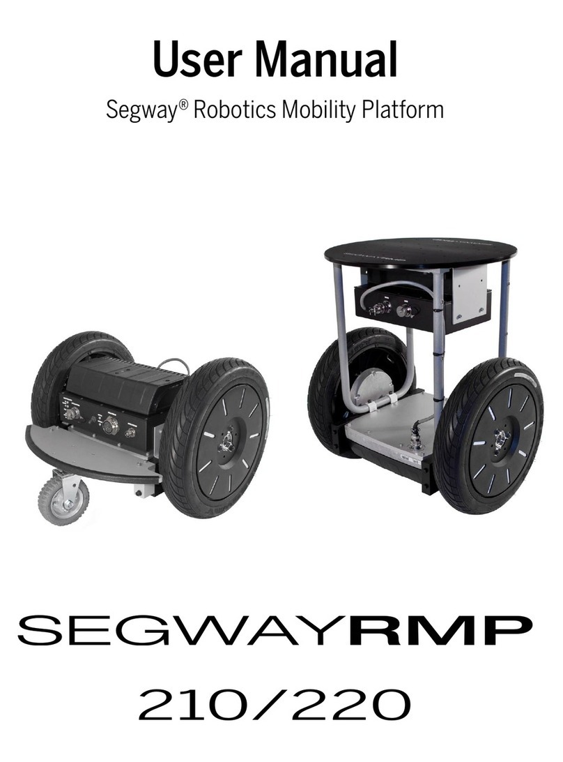
Segway RMP 440 LE V3 User manual

User Manual
Segway®Robotics Mobility Platform
RMP 440 LE V3
Robotics


3
User Manual
Contents
Copyright, Disclaimer,Trademarks, Patent, and Contact Information ..............................................................6
Introduction
Additional Information......................................................................................................................................... 7
Safety....................................................................................................................................................................8
Abbreviations ..................................................................................................................................................... 10
RMP 440 LE
Included Components.........................................................................................................................................11
Capabilities......................................................................................................................................................... 12
Physical Characteristics .................................................................................................................................... 13
Mounting Locations ........................................................................................................................................... 14
User Interface Panel........................................................................................................................................... 15
Performance Specifications .............................................................................................................................. 16
Environmental Specifications............................................................................................................................ 16
Endurance ...........................................................................................................................................................17
Transportation and Shipping............................................................................................................................. 19
Electrical Overview
System Components ......................................................................................................................................... 21
Operational Model
Operational States .............................................................................................................................................23
Faults ..................................................................................................................................................................24
Initialization........................................................................................................................................................24
Diagnostic Mode ................................................................................................................................................25
Bootloader Mode................................................................................................................................................25
Standby Mode ....................................................................................................................................................25
Tractor Mode ......................................................................................................................................................25
Disable Mode......................................................................................................................................................26
Decel To Zero (DTZ) Mode .................................................................................................................................26
Charging
Using the Power Cord ........................................................................................................................................ 27
Using the External Power Supply ......................................................................................................................28
Charge Status LEDs ...........................................................................................................................................28

4
RMP 440 LE
Powering On/Off
Powering On .......................................................................................................................................................29
Powering Off.......................................................................................................................................................29
Connecting
Connector I......................................................................................................................................................... 31
Connector II........................................................................................................................................................32
Connector III.......................................................................................................................................................33
Connector IV.......................................................................................................................................................33
Ethernet Connection..........................................................................................................................................34
Internal Connections
Hardware Controls .............................................................................................................................................35
Mode Selection ..................................................................................................................................................36
Status Indicators................................................................................................................................................36
Coin Cell Battery ................................................................................................................................................36
Maintenance
Fastener Torque..................................................................................................................................................37
Tire Pressure ......................................................................................................................................................37
Parts List ............................................................................................................................................................38
Removing Wheel Assemblies.............................................................................................................................39
Replacing Wheel Assemblies .............................................................................................................................39
Cleaning..............................................................................................................................................................39
Software Updates...............................................................................................................................................39
Batteries
Battery Care ....................................................................................................................................................... 41
Installation and Removal Instructions ..............................................................................................................42
Transportation and Shipping.............................................................................................................................42
Proper Disposal..................................................................................................................................................42
Replacing Batteries............................................................................................................................................42
Troubleshooting
Reporting Problems to Segway.........................................................................................................................43
Extracting the Faultlog.......................................................................................................................................43
Reading the Faultlog ..........................................................................................................................................43
Faults ..................................................................................................................................................................44
Charging Faults ..................................................................................................................................................48
Other Issues .......................................................................................................................................................48

5
User Manual

6
RMP 440 LE
Copyright, Disclaimer, Trademarks, Patent, and Contact Information
Copyright © 2015 Segway Inc. All rights reserved.
Disclaimer
The Segway RMP is not a consumer product. Usage examples shown on
rmp.segway.com
have not necessarily been reviewed nor
approved by Segway Inc. ("Segway"). Segway is not responsible for end customer modifications or additions.
Trademarks
Segway owns a number of trademarks including, but not limited to, Segway and the Segway "flyguy" logo that have been registered
in the United States and in other countries. Those trademarks followed by ® are registered trademarks of Segway. All other marks
are trademarks or common law marks of Segway. Failure of a mark to appear in this guide does not mean that Segway. does not use
the mark, nor does it mean that the product is not actively marketed or is not significant within its relevant market. Segway reserves
all rights in its trademarks. All other trademarks are the property of their respective companies.
Segway Patent Information
The Segway RMP is covered by U.S. and foreign patents. For a patent listing, see
http://rmp.segway.com/RMPPatents.pdf
Contact Information
For support, please contact Stanley Innovation or use the RMP forum at
http://rmp.segway.com/forum
Stanley Innovation
9 Henry Clay Drive, Merrimack, NH 03054, USA
Phone: 603-689-7083
E-mail: info@stanleyinnovation.com
Website:
http://www.stanleyinnovation.com

7
User Manual
Introduction
Introduction
The RMP 440 LE V3 incorporates Stanley Innovation's Robotics Mobility Platform V3 (RMP V3) hardware and software improvements
on top of the Segway RMP platform. The result is a product that starts with the robust and durable Segway RMP chassis and adds
features to provide greater versatility and ease-of-use.
Utilizing advanced electric drive, high quality lithium batteries, drive-by-wire control, and dynamic stabilization, these mobility
systems are ready to tackle the toughest challenges. The integration of the Robot Operating System (ROS) navigation and behavior
system allows for advanced behaviors such as mapping and navigation.
The RMP V3 utilizes a robust Ethernet protocol which allows seamless integration of IP radios. The system also has provisions for a
software update over USB so the RMP V3 can be updated whenever new code is released.
This manual describes the hardware and capabilities of the RMP V3. A separate communications manual describes the individual
messages sent to and from the platform, however, thanks to our ROS drivers most users will not have to dive that far into the system.
ROS allows for much higher level command and control so users can avoid packing bits into an Ethernet packet.
Stanley Innovation should be your first point of contact if you have any questions or concerns with your platform.You can reach us on
our website at
http://stanleyinnovation.com/contact-us/
.
Additional Information
More information on the RMP V3 can be found in the following documents and web pages:
•
http://wiki.ros.org/Robots/RMPv3
— provides information on using ROS with your RMP V3
•
http://rmp.segway.com/forum/
— a place to ask questions and receive answers about Segway RMP products
•
RMP V3 Interface Guide
— describes the Ethernet communication protocol used to talk directly to the RMP V3

8
Introduction
RMP 440 LE
Safety
Improper use of the RMP can cause personal injury, death and/or property damage from loss of control, collision, and falls. To reduce
risk of injury, read and follow all instructions and warnings in this manual.
The following safety messaging conventions are used throughout this document:
WARNING! Warns you about actions that could result in death or serious injury.
CAUTION! Warns you about actions that could result in minor or moderate injury.
NOTICE Indicates information considered important, but not related to personal injury. Examples
include messages regarding possible damage to the RMP or other property, or usage tips.
WARNING!
• Keep out of reach of children and pets. Unanticipated movement by the RMP could result in death or serious injury.
• Do not sit, stand, or ride on the RMP. Doing so could result in death or serious injury.
• Do not drive the RMP at people or animals. A collision could result in death or serious injury.
• Always alert people in the vicinity when an RMP is operating. An unexpected collision with the RMP could result in
death or serious injury.
• Avoid powering off on a slope. The RMP cannot hold its position when powered off and may roll downhill, causing
serious injury, death, or property damage.
• The RMP can accelerate rapidly. It is recommended that the RMP be securely raised so the wheels are off the ground
(or remove the wheels) until the user becomes familiar with the controls. Unanticipated movement by the RMP could
result in death or serious injury.
• Be careful when working with the DC power connections.You could shock yourself and/or damage the RMP.
• Remove batteries before working inside the RMP. You risk serious bodily injury from electric shock as well as damage to
the RMP.
• Do not submerge the RMP, batteries, or powerbases in water. Do not use a power washer or high-pressure hose to clean
a RMP. Avoid getting water into any of the connectors. If you suspect the batteries or powerbase have been submerged
or experienced water intrusion, call Segway Technical Support immediately at 1-866-473-4929, prompt #2. Until you
receive further instructions, store the RMP upright, outdoors, and away from flammable objects. Failure to do so could
expose you to electric shock, injury, burns, or cause a fire.
• Unplug or disconnect the RMP from AC power before removing or installing batteries or performing any service. Never
work on any part of the RMP when it is plugged into AC power. You risk serious bodily injury from electric shock as well
as damage to the RMP.
• The cells within the batteries contain toxic substances. Do not attempt to open batteries. Do not insert any object
into the batteries or use any device to pry at the battery casing. If you insert an object into any of the battery's ports
or openings you could suffer electric shock, injury, burns, or cause a fire. Attempting to open the battery casing will
damage the casing and could release toxic and harmful substances, and will render the battery unusable.
• As with all rechargeable batteries, do not charge near flammable materials. When charging, the batteries could heat up
and ignite a fire.
• Do not use a battery if the battery casing is broken or if the battery emits an unusual odor, smoke, or excessive heat or
leaks any substance. Avoid contact with any substance seeping from the battery. Batteries contain toxic and corrosive
materials that could cause serious injury.
• Observe and follow all safety information on the warning label found on the battery. Failure to do so could result in
death, serious injury, or property damage.
• Do not use cables that are frayed or damaged. You could shock yourself and/or damage the RMP.
• Use only Segway approved fasteners on the RMP. Other fasteners may not perform as expected and may come loose.
Failure to do so could expose you to risk of personal injury or property damage.
• Use assistance when moving or lifting the RMP. Single person lifting could result in serious injury.

9
User Manual
Introduction
CAUTION!
• Be responsible about setting performance parameters. Read the relevant sections of this manual before changing any
performance parameters. The RMP follows commands issued to it, and it is the responsibility of the user to properly
safeguard their controls.
• Failure to charge the batteries could result in permanent damage to them. Left unplugged, the batteries could fully
discharge over time, causing permanent damage.
• Use only charging devices approved by Segway and never attempt to bypass or override their charging protection
circuits.
• Always protect against electrostatic discharge (ESD) when working inside the RMP. The RMP could become damaged.
NOTICE
• This equipment has been tested and found to comply with the limits for a Class A digital device, pursuant to part 15
of the FCC Rules. These limits are designed to provide reasonable protection against harmful interference when the
equipment is operated in a commercial environment. This equipment generates, uses, and can radiate radio frequency
energy and, if not installed and used in accordance with the instruction manual, may cause harmful interference to
radio communications. Operation of this equipment in a residential area is likely to cause harmful interference in which
case the user will be required to correct the interference at his own expense.
• This Class A digital apparatus complies with Canadian ICES-003.
Cet appareil numérique de la classe a est conforme à la norme NMB-003 du Canada.
• Modifications not expressly approved by Segway may void the user's authority to operate this device under FCC
regulations and must not be made.

10
Introduction
RMP 440 LE
Abbreviations
ABB Auxiliary Battery Board — a PCB used to gather and report performance information from the auxiliary battery.
BCU Battery Control Unit — a PCB inside the battery pack that manages the charge of the individual cells.
BSA Balance Sensor Assembly — a group of PCBs used to obtain information about the vehicle's orientation.
CAN Controller Area Network — a message-based protocol used for communication between microcontrollers.
CCU Centralized Control Unit — a PCB that houses the SP, UIP, and NVM; it controls the RMP and handles communication.
CRC Cyclic Redundancy Check — a type of error-detection used to verify the accuracy of transmitted data.
DLC Data Length Code — a part of the CAN message header that specifies the size of the data packet being sent.
DTZ Decelerate To Zero — an operational mode in which the RMP comes to a stop and powers down.
LE Large Enclosure — a unified chassis/enclosure for 4-wheeled RMP models.
MCU Motor Control Unit — a PCB that controls the electric motors that turn the wheels.
NVM Non-Volatile Memory — a type of digital memory that can retain the stored information even when not powered.
OCU Operator Control Unit — software and hardware that provide an interface between the user and the RMP.
PCB Printed Circuit Board — a thin board with conductive pathways and electronic components mounted on it.
PSE Pitch State Estimate — a 3-axis inertial estimate of the orientation of the RMP.
RMP Robotics Mobility Platform — a propulsion system that can be used as a platform for making mobile robots.
ROS Robot Operating System — a set of open-source Linux tools for building and manipulating robots.
SCB Smart Charger Board — a PCB that controls battery charging functions.
SE Small Enclosure — a box that contains all of the electrical components of the RMP.
SID Standard ID — a CAN identifier that indicates the type of message being sent.
SOC State Of Charge — a measurement of battery charge from 0% (empty) to 100% (full).
SP Segway Processor — a microcontroller on the CCU that contains proprietary Segway code for controlling the RMP.
SPI Serial Peripheral Interface — a synchronous serial data link standard that operates in full duplex mode.
UDP User Datagram Protocol — a simple, transaction-oriented network protocol on top of TCP/IP.
UDFB User Defined Feedback Bitmap — a stored value that indicates what feedback data should be sent to the user.
UI User Interface — the means by which an operator interacts with a device.
UIP User Interface Processor — a microcontroller on the CCU that communicates with the OCU.
USB Universal Serial Bus — an industry-standard bus for communication and power supply between computers and peripherals.
VAB Vicor Adapter Board — a PCB that interfaces with Vicor DC-DC converters.

11
User Manual
RMP 440 LE
RMP 440 LE
The RMP 440 LE is a battery-powered Robotics Mobility Platform (RMP) meant to be used as the propulsion system for a robotic
product. It has four 21-inch all-terrain tires and two powerbases mounted to a single aluminum enclosure. Electrical components are
mounted inside the enclosure. Propulsion batteries are mounted to the bottom of the powerbases. The auxiliary battery is mounted
to the bottom of the enclosure between the two powerbases.
The on/off button, external connectors, and indicator lights are mounted on a User Interface Panel at the rear of the RMP.
Communication with the RMP occurs over Ethernet.
Inside the enclosure are the Centralized Control Unit (CCU), Auxiliary Battery Board (ABB), Smart Charger Board (SCB), and Power
Converter(s). Additional space is provided for users to install their own hardware.
Figure 1: RMP 440 LE
Figure 2: Starter Breakout Harness
Included Components
The RMP 440 LE comes with a disable button and power cord. The disable button must be connected for the RMP to enter Standby
Mode. When pressed, the disable button will cause the RMP to immediately shut down. The power cord is used to charge the RMP.
When connected, indicator lights on the User Interface Panel show the charging status of each battery.
Figure 3: Power Cord

12
RMP 440 LE
RMP 440 LE
Capabilities
The RMP is meant to be used by integrators when creating mobile robotic products. As such, the RMP was designed with flexibility
and expandibility in mind.
Driving
The RMP can drive forward, reverse, and can turn in place1. Turning is accomplished by skid steering — where the wheels actually skid
across the ground as the RMP turns. A variety of parameters can be adjusted for easier driving in different circumstances, making
it possible to have fine control at slow speeds and at high speeds. Adjustable parameters include maximum velocity, maximum
acceleration, maximum deceleration, maximum turn rate, and maximum turn acceleration.
For safety, a disable button is provided with the RMP. When pressed, the disable button will cause the RMP to shut down. A Decel To
Zero (DTZ) command can also be sent, either by hardware button (not supplied) or by software command.This command causes the
RMP to decelerate and come to a stop.
Payload
Users can mount equipment both to the outside and to the inside of the RMP. Mounting holes are provided along the sides of the
enclosure and mounting studs are provided internally. The internal space is roughly 300 mm long x 200 mm wide x 150 mm tall
(approx. 12 in long x 8 in wide x 6 in tall). For more information, see "Mounting Locations," p. 14.
The maximum total payload is 180 kg (400 lbs), evenly distributed.
Communication
Communication with the system for command and control is via Ethernet. The primary method of communication is via a ROS
driver that Stanley Innovation provides. This driver performs a Cyclic Redundancy Check (CRC) on all data and ensures that the
communication link is updated periodically to ensure the on-board firmware does not automatically slew the commands to zero.
Expansion
Central to the RMP's design is the ability for users to expand the platform's capabilities by integrating additional components. To
facilitate this Segway has provided communication and power interfaces on both the outside and inside of the platform. For details
about connecting to the RMP see "Connecting," p. 31, and "Internal Connections," p. 35.
The RMP can provide power for additional equipment. The RMP 440 LE has space for three Power Converters. For more information
see "Power Converter," p. 22.
Control Interface
Stanley Innovation provides a ROS driver. For details visit
http://wiki.ros.org/Robots/RMPv3
1Turn radius is dependent upon the friction between the RMP tires and the ground. In some circumstances the RMP may not be able to turn in place.

13
User Manual
RMP 440 LE
Physical Characteristics
For product dimensions, please refer to the diagrams below. A summary of the major dimensions is provided in Table 1.
NOTICE
Product options may change the characteristics of the RMP.
Characteristic Value
Overall
Length 1105 mm (43.5 in)
Width 842 mm (33.2 in)
Height 533 mm (21.0 in)
Chassis
Length 972 mm (38.3 in)
Width 360 mm (14.2 in)
Height 329 mm (12.9 in)
Clearance 110 mm (4.3 in)
Tires
Tire Size AT21x7-10
Wheel Base 571 mm (22.5 in)
Track Width 691 mm (27.2 in)
Recommended
Tire Pressure 6 psi
Other
Weight 120 kg (265 lbs)
Table 1: Physical Characteristics
842.01
33.15
505.18
19.89
533.40
21.00
449.87
17.71
248.20
9.77
120.90
4.76
571.74
22.51
533.40
21.00
971.60
38.25
872.85
34.36
360
14.17
1105.16
43.51
Figure 4: RMP 440 LE Top View
Figure 5: RMP 440 LE Front View Figure 6: RMP 440 LE Side View

14
RMP 440 LE
RMP 440 LE
Mounting Locations
Equipment can be mounted to the RMP using the provided mounting locations. Tapped holes are located on the sides of the
enclosure. Threaded studs are provided inside the enclosure.
External Mounting
There are 12 M6x8 tapped holes on each side of the enclosure. Dimensions are mm [in].
220
8.66
110
4.33
571.47
22.50
220
8.66
110
4.33
140
5.51
273
10.75
Figure 7: RMP 440 LE Side Mounting Holes
Internal Mounting
There are 6 M4x7 threaded studs inside the enclosure. Dimensions are mm [in].
0
.00
71
2.80
142
5.59
213
8.39
284
11.18
10.50
.41
273.50
10.77
0
.00
10.50
.41
70
2.76
129.50
5.10
140
5.51
412.38
16.24
Figure 8: RMP 440 LE Side Mounting Holes
0
.00
140
5.51
280
11.02
317
12.47
37
1.45
0
.00
193
7.59
40
1.57
Figure 9: RMP 440 LE Internal Standoffs
6.83
.27
195.10
7.68
35.16
1.38
297.18
11.70
Figure 10: RMP 440 LE Internal Equipment Space
NOTICE
Only mount equipment via the provided mounting locations. Drilling holes in the enclosure or other modifications to the RMP may
adversely affect the FCC rating, IP rating, and/or structural integrity of the RMP.

15
User Manual
RMP 440 LE
User Interface Panel
The power button, LEDs, and external connectors for the RMP are all located on the User Interface Panel on the rear of the RMP.
Users should familiarize themselves with the various connectors and LEDs. For information on the connectors and what plugs into
them see "Connecting," p. 31.
ON/OFF Button
Pressing this button for 2 seconds will start the
machine and turn on the auxiliary power supplies.
If the button is pressed during operation for 2
seconds the machine will send a power down
signal to any connected computers, wait 30
seconds for them to shut down, and then turn off
the auxiliary power.
Power and Status LEDs
These two LEDs indicate what mode the RMP is in.
They can be used to troubleshoot startup issues.
See "Powering On/Off," p. 29 for a list of what
the LEDs indicate. Figure 11: Interface Panel
Auxiliary Battery Battery 3Battery 2Battery 1Battery 0
RearFront
Figure 12: Battery Locations
Connector I
This connector is used for communication and for auxiliary power. Auxiliary power available depends on the Power Converters
installed. Up to three different DC voltages can be made available.
Connector II
The Disable Button connects here. The Disable signal must be sent for normal operation. Other signals include: the Decel Request,
used to initiate a Decel to Zero (DTZ); the Boot1 signal, used to enter Diagnostic mode; and the Boot2 signal, used to enter
Bootloader mode.
Connector III
This connector is used for connecting the RMP to AC power to charge the batteries. The power cord connects here and plugs into a
standard AC wall outlet. For more information on charging see "Charging," p. 27.
Charge Status LEDs
When charging the Charge Status LEDs will light up, indicating the status of each battery. For more information see "Charging," p.
27.

16
RMP 440 LE
RMP 440 LE
Performance Specifications
The RMP is driven by four independent and fully redundant brushless DC drive motors. It can operate both outdoors and indoors,
although the tires may damage carpet and scuff flooring. Traversable terrain includes asphalt, sand, grass, rocks, and snow.
All measurements are based on a standard RMP 440 LE with 21-inch wheels.
1 Turn-in-place capability and turning radius are dependent on the load conditions, operating surface type, tire friction, etc.
2Based on an unloaded platform.
3Based on an unloaded platform with 6 psi tires travelling in a straight line on level pavement. Actual performance may vary.
4Run time based on internal battery power. Extended run time is possible with charger connected.
5Turn-in-place and tight radius turns are not possible when operating on high traction surfaces with payloads at or near the maximum.
6The maximum payload that will allow the RMP to turn in place even on high traction surfaces.
Characteristic Value
Mobility
Max. Speed 8.0 m/s (18 mph)
Turn Radius10 minimum
Turn Envelope11105 mm (43.5 in)
Max. Slope230°
Peak Torque
(Each Wheel)
100 N-m (74 lb-ft)
Wading Depth
(Standard Gearbox)
248 mm (9.7 in)
Wading Depth
(Inverted Gearbox)
406 mm (16.0 in)
Maximum Range350 km (30 mi)
Power
Run Time4Up to 24 hours
Charge Time ~8 hours
Battery Chemistry LiFePO4
Propulsion Battery
Capacity
380 Wh each
Auxiliary Battery
Capacity
380 Wh
Payload
Max. Payload5180 kg (400 lbs) centered
High Traction Payload690 kg (200 lbs) centered
Table 2: Performance Specications
Environmental Specifications
The Segway RMP was designed to withstand environmental conditions both indoors and outdoors.
Characteristic Value
Operating Temp. Range 0°–50° C (32°–120° F)
Storage Temp. Range -20°–50° C (-5°–120° F)
Table 3: Environmental Specications

17
User Manual
RMP 440 LE
Endurance
Platform endurance is determined by measuring battery draw while performing various maneuvers.
In many cases the propulsion batteries will limit the runtime of the RMP. However, there are some scenarios in which the auxiliary
battery will be the limiting factor. Such cases include stationary operation and situations in which additional equipment is using the
auxiliary battery as a power source.
To calculate the energy used by a given maneuver, first determine the length of time the maneuver will be performed. Then multiply
that time (in hours) by the Watts used while performing the maneuver. This will give you the Watt-hours used per battery. Subtract
those Watt-hours from the Watt-hours remaining in the battery. Maximum battery capacity is 380 Watt-hours.
NOTICE
In the equations below, Power Draw (W) represents how much power is used by a single propulsion battery. Because every propulsion
battery will deplete at roughly the same rate, it is safe to assume this single battery is representative of all propulsion batteries.
Stationary Power Usage
When the RMP is maintaining a stationary position on level ground, the auxiliary battery is the limiting factor when calculating
runtime.The internal RMP components use approximately 16 Watts, allowing the auxiliary battery to last nearly 24 hours. In
contrast, the propulsion motors require only 7 Watts to maintain position on level ground, leaving 55% SOC left in the propulsion
batteries after 24 hours. During actual use, the power used by the propulsion batteries may be greater, especially if maintaining
position on a slope.
Straight Line Power Usage
The following empirical relationships can be used to provide a rough estimate of power usage when travelling in a straight line.
These relationships are based on tests performed on dry, level pavement and represent best-case scenarios. Actual performance
may vary.
Power draw for an unloaded platform:
W = 29.38 × p–0.16 × v1.137
W = Power Draw (Watts)
p = Tire Pressure (psi)
v = Velocity (m/s)
Power draw for a platform with 400 lbs additional mass:
W = 96 × p–0.5 × v1.1
W = Power Draw (Watts)
p = Tire Pressure (psi)
v = Velocity (m/s)
Figure 13: Turn-in-Place Power Usage
Turn-in-Place Power Usage
Due to the nature of scrub steering, the RMP uses considerable
power when turning in place. The information provided here is based
on tests performed on dry, level pavement with tire pressure at 6 psi
and 12 psi. Tests were performed at 1 rad/s. Greater speeds caused
the RMP to become unstable and are not recommended.Actual
performance may vary.
Above 400 Watts the RMP cannot turn continuously. This is
represented by the grey area in Figure 13.
Turn-in-place power usage at 1 rad/s can be approximated using the
following equation:
W = 2.24m + 181
W = Power Draw (Watts)
m = Additional Mass (lbs)

18
RMP 440 LE
RMP 440 LE
Turning Power Usage
When driving in circles or turning, power usage is based on the turning radius and the speed. The information provided here is
based on tests performed on dry, level pavement with tire pressure at 6 psi and 12 psi. The smaller the radius, the more power is
used. Actual performance may vary.
Figure 14 shows the power usage for an RMP with no additional mass. As mass increases, power usage also increases. The
equations below can be used to estimate power usage for an unloaded platform and for a platform with 100 lbs additional mass.
Figure 14: Turning Power Usage, Unloaded
The following empirical relationships can be used to approximate power usage when driving in circles.
Power draw for an unloaded platform:
W = (215v + 145)r–0.96
W = Power Draw (Watts)
v = Velocity (m/s)
r = Radius (m)
Power draw for a platform with 100 lbs additional mass:
W = (410v + 364)r–1.04
W = Power Draw (Watts)
v = Velocity (m/s)
r = Radius (m)

19
User Manual
RMP 440 LE
Transportation and Shipping
NOTICE
Lithium-ion batteries are regulated as "Hazardous Materials" by the U.S. Department of Transportation. For more information,
contact the U.S. Department of Transportation at
http://www.phmsa.dot.gov/hazmat/regs
or call 1-800-467-4922.
To prevent damage to your RMP, always ship it in the original crate it came in. The crate disassembles for easier storage. If you do not
have the original crate, contact Segway for a replacement (see "Contact Information," p. 6).
Characteristic Value
RMP
Packaging
Material Palletized Plywood Crate
Size 122 x 102 x 76 cm (48 x 40 x 30 inches)
Weight 140 kg (310 lbs)
Battery
Packaging
Material Corrugated Cardboard Box
Size 38 x 23 x 23 cm (15 x 9 x 9 inches)
Weight One Battery: 7 kg (16 lbs)
Two Batteries: 12 kg (26 lbs)
Label Class 9 Hazardous Materials
Commodity
Description
UN3480 Lithium-ion Batteries, 9
(Class 9 Hazardous Materials)
Ground Shipment — Batteries Installed
When shipping the RMP by ground with the batteries
installed, ship it in the original crate with a Class 9
Hazardous Materials label affixed to the outside of the
crate. Make sure that your shipper is HAZMAT certified
for Class 9 hazardous materials. See Table 4 for more
detailed information.
Characteristic Value
RMP
Packaging
Material Palletized Plywood Crate
Size 122 x 102 x 76 cm (48 x 40 x 30 inches)
Weight 165 kg (365 lbs)
Label Class 9 Hazardous Materials
Commodity
Description
UN3171 Battery Powered Equipment, 9
(Class 9 Hazardous Materials)
NMFC No. 190285 (for LTL shipments)
Class 100 (for LTL shipments)
Ground Shipment — Batteries Separate
When shipping the RMP by ground with the batteries
packaged separately, only the batteries require special
accommodation. There are no restrictions on packaging
and transportation for non-battery RMP components.
Ship the batteries in their original UN marked packaging
with a Class 9 Hazardous Materials label affixed to the
outside of each battery box. Make sure that your shipper
is HAZMAT certified for Class 9 hazardous materials. See
Table 5 for more detailed information.
Table 4: Ground Shipment — Batteries Installed
Table 5: Ground Shipment — Batteries Separate
Air Shipment — Batteries Separate
When shipping the RMP by air, package the batteries
separately. Only the batteries require HAZMAT
accommodation. There are no restrictions on packaging
and transportation for non-battery RMP components.
Ship the batteries in their original UN marked packaging
with a Class 9 Hazardous Materials label affixed to the
outside of each battery box. Also affix a "Cargo Aircraft
Only" label to the outside of each battery box. Make
sure that your shipper is HAZMAT certified for Class 9
hazardous materials. In addition, prepare 4 copies of the
DGD (Declaration for Dangerous Goods) document. See
Table 6 for more detailed information.
Table 6: Air Shipment — Batteries Separate
Characteristic Value
RMP
Packaging
Material Plywood Crate
Size 122 x 102 x 76 cm (48 x 40 x 30 inches)
Weight 140 kg (310 lbs)
Battery
Packaging
Material Corrugated Cardboard Box
Size 38 x 23 x 23 cm (15 x 9 x 9 inches)
Weight One Battery: 7 kg (16 lbs)
Two Batteries: 12 kg (26 lbs)
Labels Class 9 Hazardous Materials
Cargo Aircraft Only
Commodity
Description
UN3480 Lithium-ion Batteries, 9
(Class 9 Hazardous Materials)
Documents Declaration for Dangerous Goods,
4 copies

20
RMP 440 LE
RMP 440 LE
Table of contents
Other Segway Robotics manuals
