SEIAOTEK ST-M1602PS User manual

User Manual
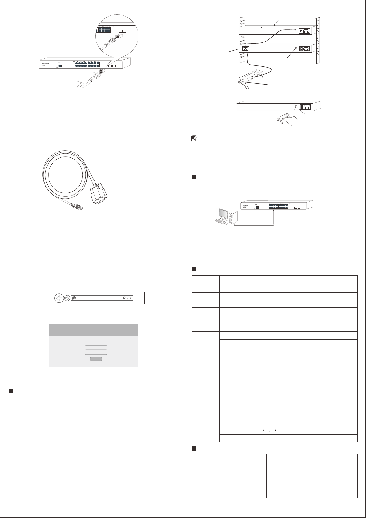
Packing List
PoE+ Switch
User Manual
Power Cable
Bracket kits
Product description
Device Installation
Installation Precautions
Note
A tamper-evident seal is sealed on a mounting screw of the switch chassis. When the
agent maintains the switch, the maintenance switch is required The seal remains intact.
If the user needs to open the switch case, please obtain the permission of the local agent.
Otherwise, due to all consequences caused by opening the cabinet will be borne by the
user himself.
Prepare the installation tools
1. Static bracelet
2. Screw driver
3. Optional: flat-blade screw driver, needle-nose pliers, diagonal pliers
Install the switch into a 19-inch standard cabinet
Step 2: Use the screws to fix the two L-shaped brackets on both sides of the switch.
Step 1: Check the grounding and stability of the rack-mountable.
To avoid damage to the switch or personal injury caused by improper use, please follow up
the below precautions:
1. During the installation procedure, wear an anti-static wristband, keep the switch powered off.
Ensure that the input voltage under the input voltage range.
2. Ensure that the heat dissipation holes of the switch are well ventilated.
3. Do not disassemble the switch.
4. Do not supply power to the switch before cleaning it. Do not use any liquid to scrub the switch.
5. Keep the switch far away from power lines, lights, and power grids.
Step 3: Place the switch in a proper position in the rack, and fix the L-shaped brackets on the
guide grooves at both ends of the rack with screws (if users required) to ensure that the
switch is installed on the rack smoothly
Install the switch to the desktop
After sticking the foot pads on the four corners of the bottom surface of the switch, please place
and keep the switch face up on the stable desktop.
PoE ports
SFP Slots
Console
Default
Ground terminal
Power connector
Interface/button Description
1-16: 10/100/1000M PoE+ ports, Support Auto-MDI/MDIX function.
17-18: Gigabit SFP Slots.
Console port: Connect the Serial Cable to the Serial port of the computer
to manage and configure the switch.
Restart or reset buttons: Press and hold this button around 10 seconds,
the switch will recovery to factory settings.
Connect the power cable with the switch.
Connect the protective ground wire to prevent lightning strikes.
Hardware connection
Connect SFP Slots
Step 1: Grab the handle end of the optic fiber module, confirm that the handle of the optic fiber module
facing upwards, and then insert the optical module into the 17~18 SFP Slots of the switch.
Step 2: After confirming the Rx and Tx ports on the optic fiber module, insert the two fiber connectors at
one end of the fiber into the Rx and Tx ports of the optical module respectively, and then plug the
two fiber connectors at the other end of the fiber into the opposite device. Tx and Rx ports.
R
PWR
Link/Act
Indicator light
ON
OFF
ON
Flashing
OFF
Switch power supply is normal
The switch is not powered on or the power supply is abnormal
Port is connected
Port is transmitting data
The port is not connected, or the connection is abnormal
Status Description
16-Port Gigabit Managed Layer 2
PoE+ Switch with 2 SFP slots
ST-M1602PS
PWR
Link/Act
1~16: 10/100/1000M PoE+ Ports
17~18: Gigabit SFP Slots
Default
Console
Ground terminal
Power connector
Power switch
Foot pad
Foot pad
Power Switch Switch on/off.
Warranty Card
Note: Please refer to the User Manual for Detail Warranty policy
Model NO.
Serial NO.
Purchase Date
RMA Number
Return Reason
Customer Name
Customer Address
Customer Email
Interface
PoE Ports 1~16: 10/100/1000M PoE+ Ports
SFP Slots 17~18: Gigabit SFP Slots
Name
Model
16-Port Gigabit Managed Layer 2 PoE+ Switch with 2 SFP slots
ST-M1602PS
Connect Rj45 port
Connect one end of the network cable to the Rj45 port of the switch, and the other end to the
RJ45 Ethernet port of the opposite network device.
Connect to the console port
Connect the RS232 DB9 male end of the serial cable to the computer, and connect the Rj45end
to the Conport port of the switch.
Connect the ground wire
Step 1: Connect one end of the ground wire to the ground terminal of the switch.
Step 2: Connect the other end of the ground wire to other equipment that has been grounded,
or directly connect it to the ground bar of the equipment room engineering terminal.
Note
Log in to the WEB Management Page
1. Connect the computer to the switch through a network cable.
2. Set the computer's local IP address to 192.168.1.X (X is 2~254, and is not occupied by other
devices), and the subnet mask is 255.255.255.0.
The ground wire of the switch should be connected to the engineering ground of the equipment
room. The grounding fire water pipe and the lightning rod of building are not properly grounded.
3. Open the computer's local browser (take IE as an example), enter http://192.168.1.1 into
the address, and press Enter to log in Switch Web Management page.
http://192.168.1.1
4. Enter the user name and password (the default is admin), and then click the login button.
Username:
Password:
Login
5. Log in to the switch web management page and start to configure the switch.
Specifications
Common Tips
What should I do if I can’t log in to the switch's web management page?
Please try the following solutions:
Confirm that the switch is powered on.
1. Confirm that the computer and the switch network cable are connected properly.
2. Confirm that the computer's Ethernet (or local connection) IP address has been set to
192.168.1.X (X is 2~254, and it is not occupied by other devices).
3. Clear the cache of the browser, or change the browser, and confirm that the connection
method of the browser is never dial connection.
4. Turn off the computer's firewall or replace a computer.
5. Confirmed that there is no other devices whose IP address is also 192.168.1.1.
6. If you still cannot log in after the above operations, please restore the factory settings.
The specific operations as follows:
7. When the Power indicator is on, press and hold the Default button on the front
panel of the switch around 10 seconds.
8. Release when all the indicators are on. When the Power indicator keeps on or the
SYS indicator flashing again, the factory settings recovery successfully.
LED
PWR , Link / Act
Store-and-forward
Half-duplex back pressure and IEEE802.3x full-drplex flow control
Bandwidth 36Gbps
Packet Forwarding Rate 26.78Mpps
MAC Address 8K
Network
Standards
IEEE802.3i 10BASE-T, IEEE802.3u 100BASE-TX,
IEEE802.3ab 1000BASE-T, IEEE802.3z 1000BASE-LX,
IEEE802.3x Flow Control, IEEE802.3az EEE,
IEEE802.1p, IEEE802.1x, IEEE802.1d, IEEE802.1s,
IEEE802.3af Power over Ethernet,
IEEE802.3at Power over Ethernet
Processing
Types
Performance
Specification
Power lnput AC 100~240V 50~60Hz
Dimension 440mm (L) x 220mm (W) x 44mm (H)
Cables UTP Cat 5 or above
Environment
Specification
Working Temperature: 0 C 45 C, Humidity: 10% ~ 90% RH non-condensing
Storage Temperature: 20°C ~ 70°C, Humidity: 5% ~ 95% RH non-condensing
Rs232 DB9 male end
Rj45 end
This switch
Other devices
Or
Ground terminal
Ground wire
Ground bar
Ground terminal
Ground wire
Ground bar
Switch
PC Cable
PoE Power Max PoE Output (Channel)
PoE Power Budget
30W
150W (250W Optional)
Other SEIAOTEK Switch manuals

SEIAOTEK
SEIAOTEK ST-IND0802PS User manual

SEIAOTEK
SEIAOTEK ST-M2402TS User manual

SEIAOTEK
SEIAOTEK ST-G16T User manual

SEIAOTEK
SEIAOTEK ST-IND0402TS User manual

SEIAOTEK
SEIAOTEK ST-M4804TX User manual

SEIAOTEK
SEIAOTEK ST-F0802PE User manual

SEIAOTEK
SEIAOTEK ST-M2404PX User manual

SEIAOTEK
SEIAOTEK ST-M4804TS User manual

SEIAOTEK
SEIAOTEK ST-IND0402MPS User manual

SEIAOTEK
SEIAOTEK ST-M2404PS User manual


Popular Switch manuals by other brands


q-Tech
q-Tech QSW-4700 Series Hardware installation and reference guide

Planet
Planet FGSW-2612PVS user manual

AVPro Edge
AVPro Edge AC-MX88-AUHD-GEN2 user manual

HYDACELECTRONIC
HYDACELECTRONIC HNS 3000 Series operating instructions

CyberView
CyberView Matrix Cat6 IP KVM user manual

Black Box
Black Box LGB1048A user manual