SEIAOTEK ST-IND0806MPS User manual

Device installation
Installation Precautions
Install equipment
Desktop installation
Industrial switches support two installation methods, desktop installation and DIN rail
installation. The following will introduce the two installation methods respectively Specific steps.
To avoid damage to the switch or personal injury caused by improper use, please observe the
following precautions.
For safety, please do not place the switch near water or damp places, and prevent water or
moisture from entering the switch case
• Please ensure that the working environment of the switch is clean. Excessive dust will cause
electrostatic adsorption, which will not only affect the life of the equipment, but also easily
cause Communication failure
• Please keep the ventilation holes of the switch unblocked, do not stack them
• Please ensure that the switch is working under a correct and stable voltage
• Before using the switch, be sure to reliably ground through the ground terminal on the rear
panel of the switch
• Before cleaning the switch, pull out the power plug of the switch. Please do not wipe the
switch with damp cloth, and do not use liquid cleaner Wash switch
• Do not open the case when the switch is working. Even when it is not powered.
Product description
Indicator light status Description
PWR ON Switch power supply is normal
OFF The switch is not powered on or the power supply is abnormal
SYS
OFF
The system is working fine
ON
The system does not start
1~14
OFF
Port is connected
Flashing Port is transmitting data
ON
The port is not connected, or the connection is abnormal
For devices without foot pads in the accessories, you can directly place the switch on a dry and
well-grounded workbench.
For the equipment with foot pads in the accessories, the specific installation process is as follows:
(1) Carefully turn the switch upside down. Clean the grooves on the bottom of the switch chassis
with a soft cloth, so that there is no oil or dust adsorption.
(2) Tear off the adhesive paper on the surface of the foot pad that comes with the machine, and
paste the foot pad into the groove on the bottom of the switch chassis.
(3) Carefully place the switch upright and place it on a clean, stable, and well-grounded workbench.
Rail installation
(1) Insert the top of the DIN rail into the notch under the rigid metal spring.
DC Indicator light
P1 Power Indicator light
P2 Power Indicator light
SYS
Front panel diagram
Side panel diagram
Console port
DC input
Recovery button (10s)
Power input P1 terminal
Power input P2 terminal
Alarm Output
Rear panel diagram
DIN-Rail
User Manual
L2 Managed Industrial-grade Fiber PoE Switch
Packing List
One PoE Switch
One User Manual
One Phoenix Terminal
Din-Rail Mounted Kits
•
•
•
•
ST-IND0806MPS
1~8: 1000Mbps PoE Port
9~14: 1000Mbps SFP Slots
PoE Indicator light
R
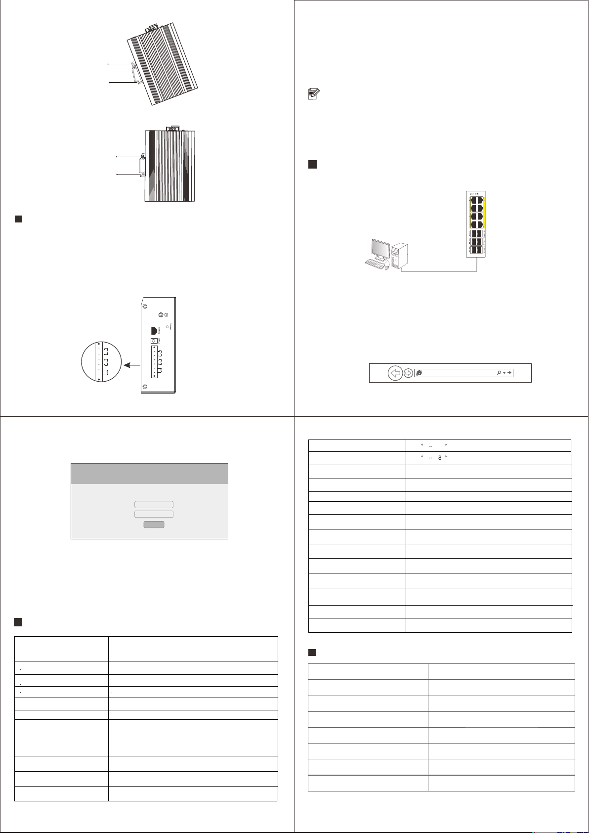
Log in to the Web GUI
1. Connect the computer to the switch with a network cable.
switch
2. Set the computer's local connection IP address to 192.168.1.X (X is 2~254, and is not
occupied by other devices), and the subnet mask is 255.255.255.0.
3. Open the computer's local connection browser (take IE as an example), enter
http://192.168.1.1 in the address bar, and press Enter to enter Switch web management
page.
http://192.168.1.1
4. Enter the user name and password (the default is admin), and then click the login button.
username:
password:
log in
5. Log in to the web management page of the switch successfully, and you can start to
configure the switch.
Specifications
cable
PC
Metal spring
DIN rail
Metal spring
DIN rail
(2) Quickly press the DIN rail base unit into the position shown in the figure below.
Redundant power input
The switch provides two redundant power inputs, that is, two power inputs of the terminal block.
If one power supply fails, the remaining power supply can still be powered to ensure that the switch
maintains a normal working state.
The two 4-pin wiring terminals on the top board of the switch have two contacts for the two DC
inputs of the switch. The schematic diagram of the wiring terminal is shown below.
note
Before connecting the DC power supply to the input of the switch, make sure that the DC
power supply voltage is stable.
1. Insert the negative/positive DC wire into the V-/V+ terminal of the terminal block.
2. In order to prevent the DC wires from loosening, please use a small flat blade screwdriver to
tighten the wires in front of the terminals Clamp the screws.
3. Insert the plastic terminal block connector into the terminal block located on the top plate of
the switch.
Interface Down ports 1-8: 10/100/1000M PoE Ports
Uplink port 9-14: 1000M SFP Slots
28Gbps
Packet Forwarding Rate 20.83Mpps
MAC Address Table 8K
Operating temperature
Stored temperature
Relative humidity
Cooling method Fanless design, natural heat dissipation
Dimension 153*128*54mm
Installation DIN-Rail mounted
IP grade IP40
Power surge protection IEC 61000-4-5 Level X (6KV/6KV)(8/20us)
Network port surge protection
Radiation immunity IEC 61000-4-3 Level 3(10V/m)
Instant pulse anti-interference
Conducted anti-interference
Power frequencymagnetic field
immunity
Voltage drop
Anti-static interference
Indicator light P2, P1, DC, SYS, SFP: Link/Activity indicator
Network Protocol
IEEE802.3i, IEEE802.3u, IEEE802.3ab
IEEE802.3z, IEEE802.3x, IEEE802.1p
IEEE802.1x, IEEE802.1d, IEEE802.1s
IEEE802.3 af, IEEE802.3 at, IEEE802.3az
Power supply Phoenix terminal, Dual redundant power supply
Voltage DC 44-57V
Switching capacity
IEC 61000-4-5 Level4 (4KV/4KV)(10/700us)
IEC 61000-4-4 Level 3(1V/2V)
IEC 61000-4-6 Level 3(10V/m)
IEC 61000-4-8 Level 3(30V/m)
IEC 61000-4-11 Level 3(10V)
IEC 61000-4-2 Level 4(8K/15K)
Port output maximum power 30W
Warranty Card
-40 C +75 C
-40 C + 5 C
Note:Please refer to the User Manual for Detail Warranty policy.
Model NO.
Serial NO.
Purchase Date
RMA Number
Return Reason
Customer Name
Customer Address
Customer Email
5%~95% RH non-condensing
Other SEIAOTEK Switch manuals

SEIAOTEK
SEIAOTEK ST-F0802PE User manual

SEIAOTEK
SEIAOTEK ST-M2404PS User manual

SEIAOTEK
SEIAOTEK ST-G08T User manual

SEIAOTEK
SEIAOTEK ST-M2404PX User manual

SEIAOTEK
SEIAOTEK ST-M2402TS User manual

SEIAOTEK
SEIAOTEK ST-M4804TX User manual

SEIAOTEK
SEIAOTEK ST-M1602PS User manual

SEIAOTEK
SEIAOTEK ST-IND0402TS User manual

SEIAOTEK
SEIAOTEK ST-G16T User manual

SEIAOTEK
SEIAOTEK ST-IND0402MPS User manual


Popular Switch manuals by other brands

ModelCraft
ModelCraft 205517 operating instructions

NETGEAR
NETGEAR WFS709TP - ProSafe Smart Wireless Controller Software administration manual

Siemens
Siemens SIMATIC NET RUGGEDCOM RS1600 installation manual

Siemens
Siemens SIMATIC NET RUGGEDCOM i801 installation manual

NuVinci
NuVinci N360 Guidelines

TESmart
TESmart HKS0201A30 user manual


