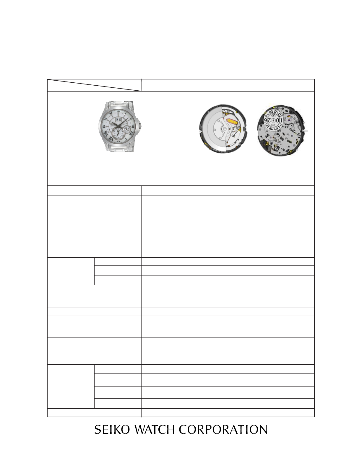
Seiko 7D56A Quick start guide

[SPECIFICATIONS]
Item Cal. No.
Power generator
Rechargeable
battery
Monthly rate: less than 15 seconds (worn on the wrist at temperature
range between 5 ºC and 35 ºC)
Nil
Use 10-second gate
Movement: less than 0.70 µA
Circuit block: less than 0.40 µA
Circuit block for calendar: less than 0.40 µA
Automatic generating system
MT920 Manganese titanium lithium rechargeable battery
0.45V - 2.50V
Validity of time relay function: approximately 4 years (from full charge)
16 jewels
1/44
PARTS LIST/TECHNICALGUIDE
KINETIC Cal. 7D56A
7D56A
Driving system
Additional function
Crown operation
Loss/Gain
Regulation system
Gate time for rate measurement
Current consumption
Power supply
Operating
voltage range
Duration of charge
Number of jewels
Normal position
1st click position
2nd click position
Coil resistance
• 3 hands (Hour/Minute/Second )
• Big calendar (Date)
• Year /Month indicator
• 24 hour indicator
Stepping motor 2 pieces and 1 piezoelectric motor for calendar
• Perpetual calendar function up to 28 Feb 2100
• Power save function
• Time relay function
• Energy depletion forewarning function
• Overcharge prevention function
• Electronic circuit reset function
• Date correction function
• Second hand stop function
Free
Calendar setting
• Diameter
Outside :
Ø 32.0 mm
Casing :
Ø 30.0 mm
• Height: 6.10
mm
Time setting
Movement
Second coil block: 2.00 - 2.45 KΩ
Hour and minute coil block:
Coil for driving hands: 1.00 KΩ- 1.25 KΩ
Coil for detecting generation: 270Ω- 330 KΩ
Generating coil block: 360 - 420Ω

Cal.7D56A
2/44
SPECIFICATIONS
SEIKO Kinetic Perpetual Cal. 7D56 is developed based on the design of SEIKO Kinetic Auto Relay Cal.
5J series with a newly designed perpetual calendar mechanism featuring a unique big date display.
Although Cal.7D series features new functions, the experience of repairing the existing KINETIC series
watches will be helpful. In repairing Cal. 7D series, you are requested to have the full knowledge of its
functions and strictly observe the repairing and checking instructions provided in this guide so that
the watch will be repaired correctly.
● POWER SAVE FUNCTION AND TIME RELAY FUNCTION
In order to conserve the stored electrical energy, the watch automatically enters power save mode
to stop the hands from moving approximately 24 hours after the watch is taken off the wrist. When
you decide to wear the watch again, simply swinging the watch several times will awaken it and
the hands will indicate the correct time to resume normal operation.
* The time retrieved by the time relay function may include a certain amount of time loss or gain within
the range of accuracy of the watch (15 seconds per month).
* In a case that the fully charged watch enters the power save mode, the time relay function of the
watch remains operable for approximately four years.
<Remarks on Power Save Function>
●When the watch is left untouched for approximately 24 hours (approximately one day), the
power save function is automatically activated.
* While the second hand is moving at two-second intervals, the power save function cannot be
activated.
●When the power save function is activated, the hour, minute, second and 24-hour hands will
stop moving.
* While the watch is in power save mode, the calendar continues to function normally.
* When the watch is left untouched in power save mode and if the date does not change correctly,
the stored electrical energy is being depleted. Recharge the watch until the watch resumes the
usual one-second interval movement, and then reset the time and calendar before starting to wear
it again.
* When the watch wakes up from power save mode while it is running on extremely low electrical
power, the second hand starts moving at two-second intervals.
● PERPETUAL CALENDAR FUNCTION
●Once set, the calendar automatically adjusts for odd and even months including February of
leap years. (Exceptionally, the manual adjustment at the end of February is required for
the years that are divisible by four but are not leap years, which comes only once every
hundred years, for example, the year 2100.)
* It takes approximately two seconds for the calendar to change its display. However, it may take
two minutes if the temperature is low or the stored electrical energy is being depleted.
●While the watch is in power save mode, the perpetual calendar continues to function.
●Even if the watch is completely stopped due to a shortage of stored electrical energy, the
calendar can be manually adjusted by simple procedures.
O
C
T
D
E
C
F
E
B
1. Each calendar item should be adjusted in sequence of year, month and
then date.
Pull out the crown to the first click.
* If your watch has a screw lock type crown, unscrew the crown first,
and then pull it out to the first click.
2. Turn the crown until the year becomes adjustable.
* Each calendar item becomes adjustable in sequence of date, month
and then year, by turning the crown.
* The calendar can be adjusted by turning the crown in either
direction upward or downward.
* The year indicator shows the number of the year(s) past since the
last leap year. When setting the year, check whether the year you
are going to set is a leap year or not, if it is not a leap year, check
how many years have passed (1, 2 or 3) since the last leap year.
FEATURES

Cal.7D56A
3/44
SPECIFICATIONS
L.Y. +1 +2 +3
2008
2012
2092
2096
2009
2013
2093
2097
2010
2014
2094
2098
2011
2015
2095
2099
Year Indication
Year
One year Two Years Three Years
Leap Year
Year indicator
O
C
T
D
E
C
F
E
B
O
C
T
D
E
C
F
E
B
O
C
T
D
E
C
F
E
B
O
C
T
D
E
C
F
E
B
CAL. 7D56
Number of the years
passed since
the last leap year
1. By swinging the watch
1. Swing the watch from side to side rhythmically at a rate of twice a second
as shown in the illustration below.
This movement will recharge the watch to start moving at the normal
one-second intervals from the two-second interval movement. If you
find the second hand moving at two-second intervals after swinging the
watch, swing it further until the second hand moves at the normal one-
second intervals.
2. By using the KINETIC Energy Supplyer YT02A
Set the crown to the 7D position.
• Make sure that the watch is correctly posi-
tioned as it may affect the amount of power
generated.
• The amount of power generated may vary de-
pending the models of the watch.
7D
* The design of the year indicator may vary depending on the model.
✶After swinging the watch, check that the second hand is moving at one-second intervals.
2. It is recommended that the watch be swung further until it can reserve enough power to run
the watch for approximately one day.
As a guideline, 200 swings will generate the power to run the watch for approximately one day.
The second hand will start moving at one-second intervals.
* To charge the rechargeable battery efficiently, swing the watch from side to side rhythmically at
a rate of twice a second, making an arc of about 20 cm.
* No additional benefit is obtained by swinging the watch more quickly or with greater vigor.
* When the electrical energy stored in the rechargeable battery is completely depleted after the
watch is left untouched for a long time, the watch requires at least 450 swings to generate
power to resume the normal operational movement.
HOW TO CHARGE THE WATCH

Cal.7D56A
4/44
SPECIFICATIONS
●Date, month and year are interlocked on the perpetual calendar. To set the month or year,
advance the date by turning the crown until the month or year becomes adjustable.
* The calendar can be adjusted by turning the crown in either direction upward or downward at the
first click position.
<Remarks on month, year settings>
When the date advances to change to "1 ," the month indicator rotates for one month to indicate
the following month. When the date advances further until the month indicator moves forward
from December (DEC) to January (JAN), the year indicator rotates to show the following year.
CAUTION
●When setting the calendar in the direction backward, put the date back for one or two days
behind the date you wish to set, and then advance it to the desired date.
* Follow the above procedure for setting the calendar in the direction backward, otherwise the date
numeral may not appear in the center of the calendar frame. Even though this happens, the date
display will be aligned correctly the following day.
* When setting the calendar backward to dates in December, the year indicator may not be correctly
aligned. In that case, set the calendar back to November then forward it to the correct date in
December.
3. Turn the crown to rotate the year/month indicator until the desired indication appears. Continue
to turn the crown until the month becomes adjustable.
Year/Month indicator
Month indicator
(Example: July)
4. Turn the crown to set the month display hand to indicate the correct month. Then continue to
turn the crown to set the date.
5. Upon completion of the calendar adjustment in sequence of year, month and date, push the
crown back into the originalposition.
Example: Date display of the 26th
Year indicator
(Example: Leap year)
HOW TO SET THE PERPETUAL CALENDAR

OSCILLATING
WEIGHT SCREW
0022 490
OSCILLATING WEIGHT
0500 531
OSCILLATING WEIGHT WHEEL
1002 504
RECHARGEABLE
BATTERY CLAMP SCREW
0012 354
RECHARGEABLE
BATTERY CLAMP
4225 542
RECHARGEABLE
BATTERY UNIT (MT920)
3023 24X
INSULATOR FOR
RECHARGEABLE
BATTERY
4216 541
CASEBACK
1
2
3
4
5
6
7
Remarks on removing the winding stem
To remove the winding stem when taking out the
movement from the case or while disassembling
the parts during repair work, be sure to pull out
the crown to the first click, and then, remove the
winding stem while pushing the setting lever.
Please refer to the remarks on the following pages.
Lubricating of some parts is shown in “ REMARKS ON DISASSEMBLING AND REASSEMBLING
THE MOVEMENT.”
[AUTOMATIC GENERATING MECHANISM]
Cal.7D56A
5/44
PARTSLIST

1.Positioning pin A for spring
for intermediate wheel
for indicator for month
CALENDAR TRAIN
BRIDGE SCREW
0012 354
DATE DISK
FOR UNIT’S DIGIT
DATE DISK
FOR TEN’S DIGIT
DATE DISK
HOLDER
0839 506
CALENDAR TRAIN
BRIDGE
0125 514
YEAR INDICATOR
DRIVING WHEEL
SPRING
0353 529
DATE JUMPER
FOR UNIT’S DIGIT
1024 500
To be removed while
assembling
To be removed while
assembling.
1. Pisitioning pin B for alignment
2.This is the repairing tool
(7D48A-JP).
Please look at the Watch
Repairing Tool Catalogue.
2. This is the repairing tool
(7D48A-JP).
Please look at the Watch
Repairing Tool Catalogue.
12
9
8
10
11
13
14
[CALENDAR UNIT (1)]
Please refer to the remarks on the following pages.
Lubricating of some parts is shown in “ REMARKS ON DISASSEMBLING AND REASSEMBLING
THE MOVEMENT.”
Cal.7D56A
6/44
PARTSLIST

MONTH INDICATOR WHEEL
1021 506
DETECTION WHEEL FOR MONTH
INDICATOR
1002 510
INTERMEDIATE YEAR
INDICATOR WHEEL
0817 516
DETECTION WHEEL FOR
YEAR INDICATOR
1002 511
YEAR INDICATOR DRIVING WHEEL
0802 512
YEAR INDICATOR WHEEL
1021 507
23
24-HOUR INDICATOR
WHEEL
1021 502
INTERMEDIATE MONTH
INDICATOR WHEEL
0817 515
21
DETECTION WHEEL
FOR 24-HOUR INDICATOR
1002 509
22
25
2ND INTERMEDIATE DATE WHEEL
0817 513
24
CALENDAR CONTROL WHEEL
1002 507
26
SCREW FOR PIEZOELECTRIC
MOTOR COVER
0022 230
27
PIEZOELECTRIC MOTOR
COVER
0839 505
Pisitioning pin B for alignment
To be set for assembling
15
16
17
18
19
20
28
PIEZOELECTRIC MOTOR
CONNECTING SPRING
1018 500
[CALENDAR UNIT (2)]
Cal.7D56A
7/44
PARTSLIST

34
MONTH INDICATOR
WHEELJUMPER
1024 504
35
INTERMEDIATE MONTH
INDICATOR WHEEL
SPRING
1024 503
36
DA
TE JUMPER FOR
TEN’S DIGIT
1024 501
Positioning pin A for spring
for intermediate wheel
for indicator for month
To be set for assembling
29
1ST INTERMEDIATE DATE WHEEL
0817 512
30
PIEZOELECTRIC ROTOR BLOCK
4146 514
31
INSULATOR FOR
PIEZOELECTRIC MOTOR
4216 540
32
PIEZOELECTRIC MOTOR CONDUCTIVE PLATE
0105 502
33
PIEZOELECTRIC STATOR BLOCK
4583 500
[CALENDAR UNIT (3)]
Please refer to the remarks on the following pages.
Lubricating of some parts is shown in “ REMARKS ON DISASSEMBLING AND REASSEMBLING
THE MOVEMENT.”
Cal.7D56A
8/44
PARTSLIST

45
CIRCUIT BLOCK FOR
CALENDAR
4000 669
37
CALENDAR PLATE
4408 563
38
DATE DRIVING WHEEL
FOR TEN'S DIGIT
0802 506
39
DATE PINION
FOR TEN'S DIGIT
1013 504
40
CALENDAR CORRECTOR
3RD INTERMEDIATE WHEEL
0962 501
41
CALENDAR CORRECTOR
4TH INTERMEDIATE
WHEEL
0962 502
43
3RD INTERMEDIATE DATE
WHEEL
0817 514
44
HOUR WHEEL
0271 564
46
CONNECTOR B
4313 582
47
CONNECTOR A
4313 581
48
PIEZOELECTRIC MOTOR
SETTING LEVER
0981 500
49
CONTROL WHEEL
JUMPER
1024 502
42
CALENDAR CORRECTOR
2ND INTERMEDIATE WHEEL
0962 559
50
EARTHING SPRING
4281 510
[CALENDAR UNIT (4)]
Please refer to the remarks on the following pages.
Lubricating of some parts is shown in “ REMARKS ON DISASSEMBLING AND REASSEMBLING
THE MOVEMENT.”
Cal.7D56A
9/44
PARTSLIST

SCREW FOR CIRCUIT
BLOCK COVER A
0012 354
CIRCUIT BLOCK COVER A
4457 505
CIRCUIT BLOCK COVER D
4457 774
SCREW FOR CIRCUIT
BLOCK COVER C
0012 354
CIRCUIT BLOCK COVER C
4457 966
OSCILLATING WEIGHT
BRIDGE
0198 503
INTERMEDIATE WHEEL
FOR AUTOMATIC
GENERATING
1002 505
CIRCUIT BLOCK
4000 594
51
52
53
54
55
56
57
58
Please refer to the remarks on the following pages.
Lubricating of some parts is shown in “REMARKS ON DISASSEMBLING AND REASSEMBLING THE
MOVEMENT.”
[CIRCUIT BLOCK]
Cal.7D56A
10/44
PARTSLIST

73
67
59
INSULATOR FOR CIRCUIT BLOCK
4216 538
60
GENERATING COIL BLOCK
4002 525
61
SECONDS COIL BLOCK
4002 524
63
TRAIN WHEEL BRIDGE
SCREW
0012 354
65
TRAIN WHEEL BRIDGE
0125 556
SECONDS WHEEL
0240 506
FOURTH WHEEL
0241 566
69
70
GENERATING ROTOR
4146 522
SECONDS ROTOR
4146 521
INTERMEDIATE MINUTE WHEEL
0766 553
75
76
CENTER WHEEL BRIDGE
4283 557
78
SETTING LEVER JUMPER
0388 558
64
CENTER WHEEL
0221 712
62
HOUR AND MINUTE
COIL BLOCK
4002 530
66
INTERMEDIATE SECONDS
WHEEL
0317 557
68
THIRD WHEEL
0231 556
71
72
HOUR AND MINUTE ROTOR
4146 523
SETTING WHEEL
0281 552
74
MINUTE WHEEL
0261 553
77
SETTING LEVER JUMPER
SCREW
0012 354
79
SETTING LEVER
0383 557
67
73
[MOTORS/GEAR TRAIN MECHANISM/SETTING MECHANISM (1)]
Please refer to the remarks on the following pages.
Lubricating of some parts is shown in “REMARKS ON DISASSEMBLING AND REASSEMBLING THE MOVEMENT.”
Cal.7D56A
11/44
PARTSLIST

YOKE
0384 557
TRAIN WHEEL SETTING LEVER
0391 557
CLUTCH WHEEL
0282 523
85
RECHARGEABLE
BATTERY CONNECTION(+)
4271 522
87
80
81
84
SECONDS STATOR
4239 523
83
SETTING STEM
CALENDAR CORRECTOR
1ST INTERMEDIATE
WHEEL
0962 557
GENERATING STATOR
4239 527
86
88
89
HOUR AND MINUTE
STATOR
4239 522
90
CROWN POSITION
DETECTING PIN
0027 369
82
MAIN PLATE
0100 567
[SETTING MECHANISM (2)]
Please refer to the remarks on the following pages.
Lubricating of some parts is shown in “REMARKS ON DISASSEMBLING AND REASSEMBLING THE MOVE-
MENT.”
Cal.7D56A
12/44
PARTSLIST

Cal.7D56A
13/44
PARTSLIST
lHow to find the correct parts, if not determined by 4 digit caliber number
Remarks
Code for DATE
DISK FOR
UNIT’S DIGIT
Code for DATE
DISK FOR TEN’S
DIGIT
Color of figure Color of back-
ground
0878 A90 0878 A91 Black White
0878 B06 0878 B05 White Black
9 DATE DISK FOR TEN'S DIGIT 10 DATE DISK FOR UNIT'S DIGIT
82 SETTING STEM
Following parts are determined based on the design of watches, such as hands height, dial color,
and design of cases. Please refer to the SEIKO WATCH PARTS CATALOGUE in order to choose
corresponding parts.

Distinction between the hour and
minute rotor and the seconds rotor
Cal.7D56A
14/44
PARTSLIST
DISTINCTION AMONG THE DIFFERENT TYPES OF JUMPERS
36 DATE JUMPER FOR TEN’S DIGIT
34 MONTH INDICATOR WHEEL JUMPER
1024504
35 IMMEDIATE MONTH INDICATOR
WHEEL SPRING
1024503
11 DATE JUMPER FOR UNITS DIGIT
12 YEAR INDICATOR DRIVING WHEEL SPRING
0353529
lHow to discriminate resembled parts
lTools and consumables required for disassembling/reassembling
• Movement holder
Universal movement holder (S-682)
• Watch oils
SEIKO watch grease (S-6) and watch oils (AO-3 and AO-2)
S-6 AO-2
AO-3
* The Cal. 7D series requires a precise alignment of its calendar train wheels, jumpers and
springs. These two positioning pins will increase an efficiency of assembling them in
correct positions.
1024501
1024500
HOUR AND MINUTE ROTOR and SECONDS ROTOR
JUMPERS
Positioning pin set (set of 2pins) for
Cal.7D series. Positioning pin B Positioning pin A
71 H o u r a n d
minute rotor
70 Seconds rotor
4146 523 4146 521

Push here.
Cal.7D56A
15/44
TECHNICALGUIDE
REMARKS ON DISSASEMBLING AND REASSEMBLING THE MOVEMENT
lHow to remove the SETTING STEM before dismantling the movement
Crown position: 1st CLICK POSITION
Push the SETTING LEVER gently (refer to the picture on
the right) in order to disengage it from the SETTING
STEM.
Then pull out the crown with the stem completely.
* After dismantling the movement from the case,
push back the crown with the SETTING STEM to the
movement.

79 SETTING LEVER
80 YOKE
81 TRAIN WHEEL SETTING LEVER
•Make sure that the spring portion of the YOKE
(“A” in the illustration) makes secure contact
with the pin.
•Lubricating
See the illustration at right.
CLUTCH WHEEL
“A” portion
YOKE
SETTING LEVER
•When installing the SETTING LEVER, insert the
tube on its underside properly into the long
slot of the TRAIN WHEEL SETTING LEVER (“B” in the
illustration). To facilitate the setting procedure,
push the TRAIN WHEEL SETTING LEVER in the
direction of the arrow in the illustration before
installing the SETTING LEVER.
Note: If a defective contact occurs between
the spring portion of the YOKE and the
pin, the manual power save function
may not be activated.
“B” portion
TRAIN WHEEL SETTING LEVER
13
77 SETTING LEVER JUMPER SCREW
78 SETTING LEVER JUMPER
•How to install
·Check that the SETTING LEVER JUMPER
is securely set in position before tightening
the SETTING LEVERJUMPER SCREW.
·Then, gently bend the spring portion of
the SETTING LEVER JUMPER so that it
catches the tube of the setting lever.
Note: Take care not to bend the spring
portion more than necessary.
•Lubricating
See the illustration at right.
SETTING LEVER JUMPER
SCREW
TUBE OF THE SETTING LEVER
Cal.7D56A
16/44
TECHNICALGUIDE
lSetting mechanism

Cal.7D56A
17/44
TECHNICALGUIDE
lGear train mechanism
43 CENTER WHEEL BRIDGE
•Setting position
See the illustration at right.
•How to install
“A” and “B” portions have elasticity and
are made tight for the guide tubes to which
they are set. After setting the spacer for
CENTER WHEEL AND PINION, press down those
portions so that it is well seated in position.
“A” portion “B” portion
Note: Take utmost care not to deform or
damage the portion that makes
contact with the CENTER WHEEL
AND PINION.

Note: Be sure to observe the position, type of oil and quantity of lubrication specified in the illustration.
Lubricating: :AO-3
MINUTE WHEEL
CENTER WHEEL
SETTING WHEEL
INTERMEDIATE
MINUTE WHEEL THIRD WHEEL FOURTH
WHEEL
HOUR AND
MINUTE ROTOR
•Lubricating
For the lubrication of these parts, refer to the illustrations below.
:AO-2
70 SECONDS ROTOR 71 HOUR AND MINUTE ROTOR 67 FOURTH WHEEL 68 THIRD WHEEL
72 SETTING WHEEL
Cal.7D56A
18/44
TECHNICALGUIDE
For the discrimination and setting position of the parts, refer to the table below.
Notes
* Take care not to mistake
the the INTERMEDIATE
SECOND WHEEL for the
THIRD WHEEL.
* They can be discriminated by
the thickness of the pinions.
Notes
* Take care not to mistake the
THIRD WHEEL and PINION FOR
THE INTERMEDIATE SECONDS
WHEEL.
* They can be discriminated by the
thickness of the pinions (THE
THIRD WHEEL AND PINION has
the thicker pinion)
Thickness
of the
pinion
*Make sure the INTERMEDIATE
MINUTE WHEEL is put in the
correct direction
(see the illustration below).
74 MINUTE WHEEL
65 SECONDS WHEEL
66 INTERMEDIATE SECONDS
WHEEL
73 INTERMEDIATE MINUTE
WHEEL

56 OSCILLATING WEIGHT BRIDGE
57 INTERMEDIATE WHEEL FOR AUTOMATIC GENERATING
69 GENERATING ROTOR
·Lubricate the ball-bearing of the OSCILLATING WEIGHT BRIDGE as shown below before reassembling
it to the MAIN PLATE.
·Lubricate the upper and lower pivots and other portions of the GENERATING ROTOR and
INTERMEDIATE WHEEL FOR AUTOMATIC GENERATING as shown in the illustration.
INTERMEDIATE WHEEL
FOR AUTOMATIC
GENERATING
GENERATING
ROTOR
Note: Be sure to observe the position, type of oil and quantity of the lubrication specified in the
illustration.
INTERMEDIATE WHEEL
FOR AUTOMATIC
GENERATING
OSCILLATING WEIGHT BRIDGE
Cal.7D56A
19/44
TECHNICALGUIDE
13
SECONDS
ROTOR
INTERMEDIATE
SECONDS WHEEL
SECONDS WHEEL
Notes:
* Lubricate the MINUTE WHEEL before reassembling
it to the TRAIN WHEEL BRIDGE. When lubricating it,
take care not to stain the pinion with oil.
* Do not lubricate the lower pivots of the THIRD WHEEL
and INTERMEDIATE SECONDS WHEEL excessively.
Be sure to observe the specified quantity.
lAutomatic generating mechanism
lCalendar mechanism
Refer to pages 21 to 31.

1 OSCILLATING WEIGHT SCREW
·Before tightening the OSCILLATING WEIGHT SCREW,
check that the gear of the OSCILLATING WEIGHT
WHEEL securely engages with the pinion of the
INTERMEDIATE WHEEL FOR GENERATING ROTOR
(“A”portion in the illustration).
·Tighten the OSCILLATING WEIGHT SCREW firmly,
applying more force than usual. If the
OSCILLATING WEIGHT SCREW becomes loose,
electricity generation will be defective.
2 OSCILLATING WEIGHT
•Lubricating
Lubricate the BALL-BEARING of the OSCILLATING
WEIGHT as shown in the illustration at right.
Note: Be sure to lubricate at the position and
in the quantity specified in the
illustration.
•How to remove
Insert the tip of the tweezers into the “A”
portion gap in the illustration, and pry up the
rechargeable battery unit to remove it.
•How to install
Set the minus lead terminal to the guide post
“B” in the illustration, push “C” portion down
vertically so that the rechargeable battery unit
is well seated in position.
Notes:
* Take utmost care not to short-circuit the (+) and (–) terminals, as this will deteriorate the battery unit.
* Never clean the rechargeable battery unit, as it is an electronic part containing an IC.
OSCILLATING WEIGHT SCREW
“A” portion
“C” portion
“A” portion
7 Rechargeable battery unit
“B” portion
Minus lead terminal
Cal.7D56A
20/44
TECHNICALGUIDE
Table of contents
Other Seiko Watch manuals

Seiko
Seiko AUTO CALENDAR J User manual

Seiko
Seiko 4R35 User manual

Seiko
Seiko 6A32 Installer manual

Seiko
Seiko 7T11 User manual

Seiko
Seiko S141 User manual

Seiko
Seiko 6R21 User manual

Seiko
Seiko ASTRON User manual

Seiko
Seiko Telemeter Operating instructions

Seiko
Seiko Cal. 8L35 User manual

Seiko
Seiko 5M62 User manual

Seiko
Seiko H024A Quick start guide

Seiko
Seiko C-21 User manual

Seiko
Seiko ANALOGUE QUARTZ SOLAR V145 User manual

Seiko
Seiko 7B26 User manual

Seiko
Seiko Alba User manual

Seiko
Seiko Pulsar 7T32 User manual

Seiko
Seiko M-3 User manual

Seiko
Seiko 7002 User manual

Seiko
Seiko 5M45 User manual

Seiko
Seiko 7K52 User manual