Seikom Electronic NLSW 75-AEx User manual
UserManual
NLSW®75-A Ex (Gg)&
Sensor F3.x Ex
24 V AC, 24 V DC, 230 V AC
Version 1.0

User Manual
NLSW®75-A Ex (Gg) & Sensor F3.x Ex
Page 2
+49 2058 2044 •info@seikom-electronic.com •www.seikom-electronic.com
The person installing the devices as well as the system operator are obligated to ensure the
satisfaction of the mandatory national ex-legislation.
Electrostatic charges on plastic parts and wires must be avoided.
The devices must be protected from any damage. Stray radiation must be avoided.
The wire connecting the flow sensor must be attached to stationary surfaces and must be
protected from any harm.
The product fulfills the requirements specified in the European directives WEEE 2012/19/EU
and RoHS 2011/65/EU.

User Manual
NLSW®75-A Ex (Gg) & Sensor F3.x Ex
+49 2058 2044 •info@seikom-electronic.com •www.seikom-electronic.com
Page 3
CONTENT
1. PREAMBLE ....................................................................................................................... 4
1.1 Safety Instructions .................................................................................................................. 4
2. GENERAL INFORMATION ON EXPLOSION PROTECTION..................................................... 4
2.1 Electrical specifications for Ex-i ............................................................................................... 5
2.2 Intrinsically safe parameters.................................................................................................... 5
2.3 Sensor Properties for Series F3.x Ex ......................................................................................... 6
2.4 Type code ............................................................................................................................... 6
2.5 Dimensions of the air flow sensors F3.x Ex ............................................................................... 7
2.5.1 F3 Ex ................................................................................................................................... 7
2.5.2 F3.1 Ex ................................................................................................................................ 7
2.5.3 F3.2 Ex ................................................................................................................................ 7
2.6 Temperature class .................................................................................................................. 7
2.7 General requirements ............................................................................................................. 8
2.7.1 Intended use........................................................................................................................ 8
2.7.2 General safety instructions .................................................................................................. 8
3. INSTALLATION AND COMMISSIONING .............................................................................. 8
3.1 Installation conditions of the air flow sensors F3.x Ex..............................................................10
3.2 Installation.............................................................................................................................10
4. MAINTENANCE AND SERVICE ......................................................................................... 11
4.1 Definitions .............................................................................................................................11
5. TROUBLESHOOTING....................................................................................................... 12
6. DISPOSAL ...................................................................................................................... 12
7. LABELLING OF THE AIR FLOW SENSORS F3.X EX............................................................. 12
8. GENERAL DESCRIPTION NLSW®75-A EX.......................................................................... 13
9. TECHNICAL DATA OF THE AIR FLOW MONITORS NLSW®75-A EX...................................... 13
10. INSTALLATION OF THE AIR FLOW MONITORS NLSW®75-A EX .......................................... 14
10.1 Commissioning and switch-point adjustment......................................................................14
11. EU KONFORMITÄTSERKLÄRUNG ............................................... Error! Bookmark not defined.

User Manual
NLSW®75-A Ex (Gg) & Sensor F3.x Ex
Page 4
+49 2058 2044 •info@seikom-electronic.com •www.seikom-electronic.com
1. PREAMBLE
1.1 Safety Instructions
Please read the entire operating instructions to ensure the full operational capability of the devices
and your own safety before starting their installation. If questions arise you may contact the
manufacturer SEIKOM Electronic GmbH & Co.KG directly. The directions, contained in these
operating instructions, must be followed.
The following standards were considered in the evaluation of the product:
a) IEC 60079-0:2017 Ed. 7 ”Explosive atmospheres –Part 0: Equipment –General
requirements “
b) IEC 60079-11:2011 Ed. 6 + Corr. 2012 / EN 60079-11:2012 ”Explosive atmospheres –Part
11: Equipment protection by intrinsic safety “i” “
c) TRGS 727:2016 “Vermeidung von Zündgefahren infolge elektrostatischer Aufladung“
2. GENERAL INFORMATION ON EXPLOSION PROTECTION
The intrinsically safe air flow sensor measures air flow velocities in the range of 0.1 ... 20.0 m/s via
the calorimetric principle. According to the operating principle either the degree of cooling (cooling
method) or the required amount of heat, necessary to maintain the heating sensor elements’
temperature constant (constant temperature method), is determined to indicate flow.
The air flow sensors of the series F3.x Ex are built for commercial use and shall only be used according
to the technical documentation provided by SEIKOM-Electronic GmbH & Co.KG and specifications on
their labels. The air flow sensors shall only be operated with certified products via an intrinsically safe
electrical circuit, which is fed by Zener-barriers. These barriers satisfy valid standards and provisions.
The general provisions on the construction of facilities in areas exposed to explosion hazards (e.g.,
EN 60079-14) need to be considered. Additional important details can be found in the alongside
delivered EC type examination certificate.
The requirements regarding simple electrical utilities applicable within areas exposed to explosion
hazards due to gases in zone 1 according to EN 60079-11 are satisfied.
In accordance with its label, the air flow sensor can be used as specified below:
➢In zone 2 (Gas-Ex, EPL Gc) in ex-groups IIA, IIB und IIC.
The qualification concerning the surface temperature is T4. The equipment does not present an
ignition source for any gases, vapours and fogs with an ignition temperature above 135 °C.
The permissible ambient temperature range for the air flow sensor is -10°C ≤Ta ≤50°C. The
permissible ambient temperature range for the NLSW®75-A Ex evaluation electronics goes from -20°C
≤Ta ≤50°C. The permissible media temperature (air flow sensor) is 0°C ≤T ≤60°C.
Self-heating is generally negligible; in case of failure the threshold values of temperature class T4
may be reached.
User Manual
NLSW®75-A Ex (Gg) & Sensor F3.x Ex
+49 2058 2044 •info@seikom-electronic.com •www.seikom-electronic.com
Page 5
2.1 Electrical specifications for Ex-i
When installing, please note that the Z- barriers BZE804 and BZE805 have different values.
If the barriers are swapped, the airflow monitor NLSW®75-A Ex will not work properly.
2.2 Intrinsically safe parameters
Type
Value
Ui
25 V DC
Ii
80 mA
Pi
0.35 W @ 40°C
0.24 W @ 110°C
Ci
negligible
Li
negligible

User Manual
NLSW®75-A Ex (Gg) & Sensor F3.x Ex
Page 6
+49 2058 2044 •info@seikom-electronic.com •www.seikom-electronic.com
2.3 Sensor Properties for Series F3.x Ex
Type
F3 Ex
F3.1 Ex
F3.2 Ex
F3.3 Ex
Article-No.
50276Ex/50
50276Ex/130
50276Ex/165
50276Ex/300
Approx. Immersion depth
50 mm
130 mm
165 mm
300 mm
Permissible
media temperature
0°C … 60°C
Permissible
ambient temperature
-10°C … 50°C
Temperature gradient
10 K/min
Connection
PG7
Probe tube material
CuZn39Pb2, nickel-plated
Compression strength
10 bar
Electrical connection
2.5 m / 3 x 0.75 mm2
Protection class
IP67
Evaluation unit
NLSW®45-3 Ex, NLSW®75-A Ex
Wire colors
Black numbered
Tested according to DIN EN 61010-1:2011-07
by TÜV Nord
2.4 Type code
There is only one kind of flow sensor F3, the different types vary only by their length. Please review
the table shown above.
User Manual
NLSW®75-A Ex (Gg) & Sensor F3.x Ex
+49 2058 2044 •info@seikom-electronic.com •www.seikom-electronic.com
Page 7
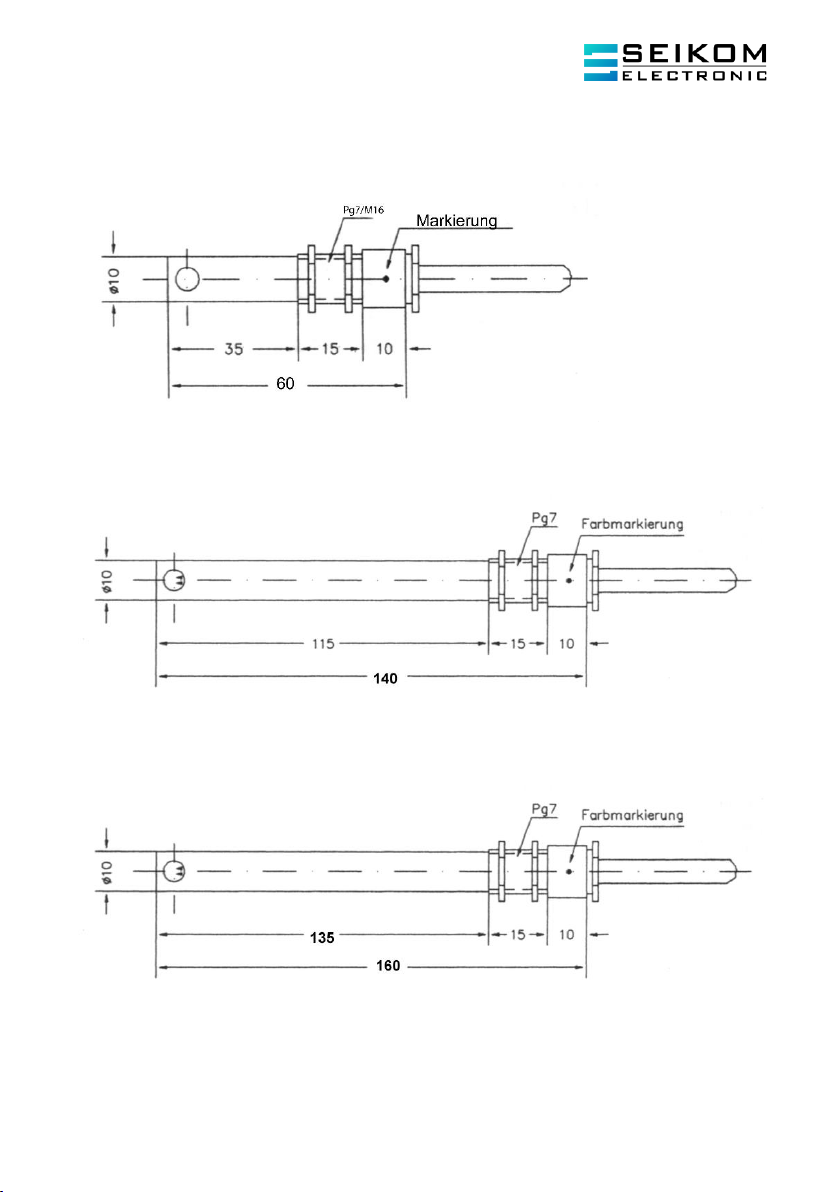
2.5 Dimensions of the air flow sensors F3.x Ex
2.5.1 F3 Ex
2.5.2 F3.1 Ex
2.5.3 F3.2 Ex
2.6 Temperature class
The sensors are suitable for use with temperature class T4.

User Manual
NLSW®75-A Ex (Gg) & Sensor F3.x Ex
Page 8
+49 2058 2044 •info@seikom-electronic.com •www.seikom-electronic.com
2.7 General requirements
2.7.1 Intended use
a) Safe use can only be ensured if the devices are used according to the specifications of the
operating instructions provided in this document. Moreover, the legal and safety
requirements specific to the individual use must be satisfied. This is also applicable to the
use of additional equipment such as accessories.
b) Incorrect use of the product or deviation from the directions contained by this instruction
result in a cancellation of our liability. Furthermore, any warranty on products or spare
parts will be cancelled.
c) The products are no safety features in the scope of their dedicated use.
d) Only original parts from the manufacturer can be used.
2.7.2 General safety instructions
The sensor corresponds to the best available technology and is reliable in operation. If installed
or operated incorrectly, for instance due to installation or operation by unqualified personnel, a
residual risk may arise from the sensor.
Any person conducting the installation, start-up, maintenance or repair of the air flow sensors
and monitors must have read and understood the operating instructions and especially the
safety instructions.
a) Consider general engineering rules and the dedicated use when choosing a product.
b) All electrical and mechanical equipment must be suitable for their intended use.
c) Pay attention to the information provided in this manual as well as the permissible
operating conditions printed on the label/type plate of the respective product.
d) Ensure that only products with the required ignition protection type, depending on the
zone, are installed!!
e) The products are only approved for their designated and appropriate use in ordinary
industrial atmosphere. Immersion in liquids is impermissible.
f) Ensure that no falling objects may hit the product. In connection with rust (corrosion),
light metal and kinetic energy an exothermal, ignitable reaction can result.
g) The operator has to ensure the lightning protection according to local regulations.
h) Follow general engineering rules when choosing and operating products.
i) The person performing the installation of the air flow sensors and their connection to the
flow monitors is responsible for their correct function and must ensure that they are
eligible for their intended use.
j) The intrinsically safe connection, including the air flow sensors, must be carried out via
approved flow monitors, which, if necessary, must be installed with suitable Zener-
barriers or switching amplifiers.
3. INSTALLATION AND COMMISSIONING
Depending on the IP protection class time intervals for cleaning of the equipment (accumulation of
dust) must be set. Additional important facts:
a) The product can be installed in zone 2 (Cat. 3G, EPL Gc) or in zone 1 (Cat. 2G, EPL Gb) in
intrinsically safe electrical circuits by professionals equally competent to qualified
personnel according to TRBS 1203.
b) The information provided on the label must be followed bindingly during installation.

User Manual
NLSW®75-A Ex (Gg) & Sensor F3.x Ex
+49 2058 2044 •info@seikom-electronic.com •www.seikom-electronic.com
Page 9
c) The products can only be operated in ordinary industrial atmosphere. The manufacturer
must be contacted if the atmosphere contains aggressive components. In case of adverse
ambient conditions, the sensors need to be protected accordingly.
d) Usage of the devices is only permissible when they are fully mounted and connected in an
intact condition. Damages would enable a zone entrainment which must therefore be
considered by the operator. Usage of devices with damaged casing is not permitted.
e) The defined permissible ambient conditions must be met, the products must be protected
from adverse ambient conditions.
f) Thermal radiation of other components and products must be considered.
g) The air flow sensors must be protected from impermissible inflow of liquids and/or
pollution.
h) Tight or stuck parts, e. g. due to frost or corrosion, cannot be loosened with force if
exposed to an explosive atmosphere. Icing must therefore be avoided.
i) The air flow sensors can only be exposed to minor vibrations, see IEC 34-14.
j) To ensure the dissipation of electrostatic charges, national regulations must be considered.
k) Especially capacities that build up in an isolated manner must be avoided.
l) The flow sensor housing should be connected to the potential equalization
electrostatically, a threshold value of 1MΩis permissible.
m) Only Zener-barriers and switching amplifiers with Ex-area approved output circuits can be
used. In Europe the use within zone 1 requires an EC type examination for the relevant
equipment, issued by a for explosion protection appointed authority.
n) The power P0 of all supply units combined must be lower or equal to the power Pi of the
air flow sensors.
o) The supply voltage of the supply units must be lower or equal to the voltage Ui of the air
flow sensors.
p) The current Io of all supply units combined must be lower or equal to the current Ii of the
air flow sensors.
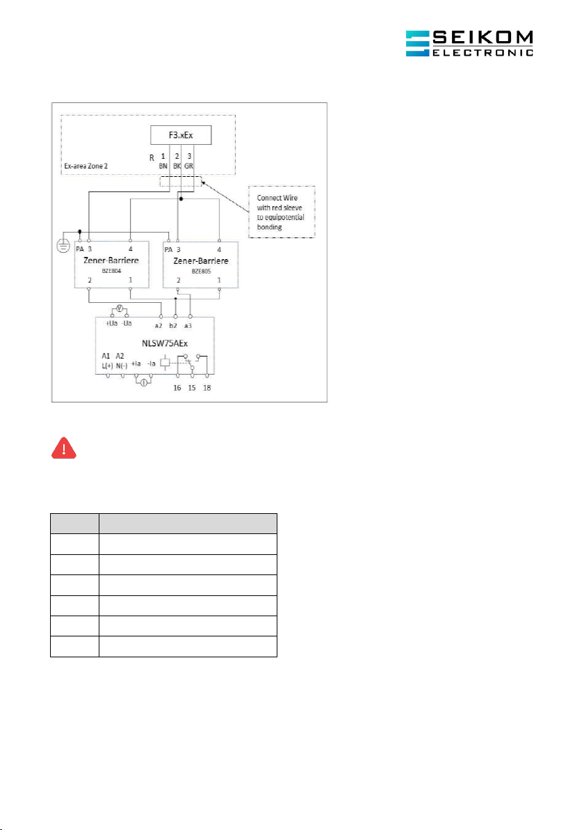
q) For the installation of an intrinsically safe electrical circuit, a block diagram (system
description) is necessary, which must be provided by the builder or operator.
r) If a Zener-barrier is used, a potential equalisation between the grounding connection and
the flow sensor casing alongside the intrinsically safe electrical circuit must be ensured.
s) The certificates including the therein defined special conditions must be considered.
t) Tight or stuck parts, e. g. due to frost or corrosion, cannot be loosened with force if
exposed to an explosive atmosphere.
u) The flow sensors cannot be used in facilities with cathodic corrosion protection. Although
special precautions might enable the use of the flow sensors in this special case, the
manufacturer must be contacted in any scenario. Parasitic currents cannot be discharged
via the construction.
v) Within the area exposed to an explosion hazard the installation must comply with local
regulations.
The following conditions must be met:
a) Installation and maintenance may only be executed in atmospheres without any explosion
hazard and in compliance with the applicable national regulations depending on the
location of operation.
b) Additional precautions must be made if hydrogen sulphide, ethylene oxide or carbon
monoxide may be or are present. These substances require only very low energy to ignite.
c) In case these substances and a substance of explosion group IIC and a presumably
explosive atmosphere are present only non-arcing tools can be used!
User Manual
NLSW®75-A Ex (Gg) & Sensor F3.x Ex
Page 10
+49 2058 2044 •info@seikom-electronic.com •www.seikom-electronic.com
3.1 Installation conditions of the air flow sensors F3.x Ex
Please consider the following points while mounting the air flow sensors to avoid any malfunction:
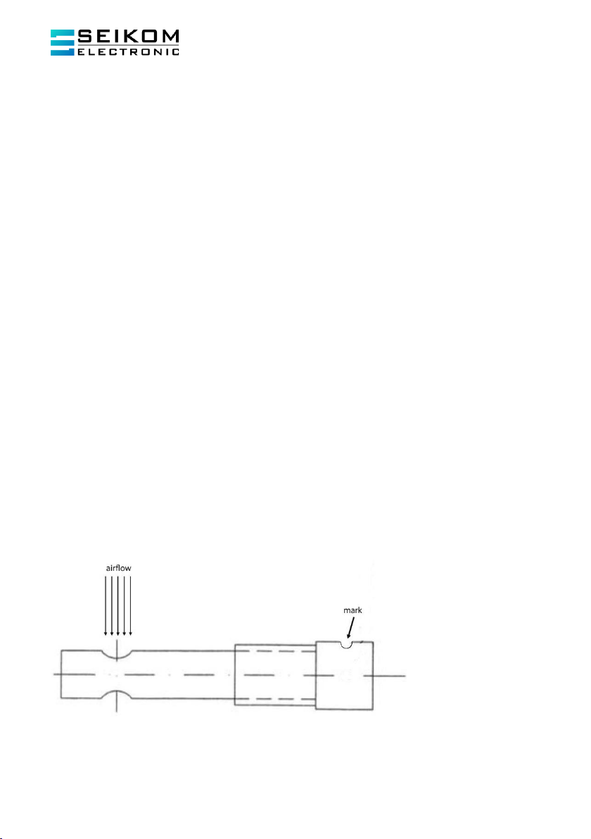
a) The tip of the sensor should be placed in the centre of the tube. The gaseous medium
must fully flow through the drilled hole located within the tip section of the sensor.
b) The mark on the base of the sensor may be used to verify whether the opening of the
drilled hole points in the direction of the flow.
c) In case of vertical tubing the direction of flow should be upwards. An inlet zone of 5xD,
before the sensor, and an outlet zone of 3xD, after the sensor should be maintained
(D=inner diameter of the pipe).
d) The air flow sensor must be connected with the air flow monitor according to the block
diagram. Any alteration of the connections leads to malfunction and may result in defects.
e) The shield must be connected to the potential equalization.
f) An extension of the sensor wiring (shielded) is only permitted if the wiring is used in non-
explosive atmosphere. Yet, a total length of 30 m at a minimum cross section of 1,5 mm²
cannot be exceeded.
During operation the following points concerning the wiring must be considered:
a) In case of flexible mounting the applicable temperature range is -5 °C up to +80 °C with a
minimum bend radius of 10x wire diameter.
b) In case of stationary mounting the applicable temperature range is -40 °C up to +80 °C
with a minimum bend radius of 10x wire diameter.
The wiring is not eligible for outdoor use or burying in the ground. Please contact the manufacturer if
the present operating conditions deviate from the specifications.
3.2 Installation
The sensor can be mounted via the PG7 connected to the sensor housing. Furthermore, mounting
can be supported by the alongside delivered PG7-nuts. During mounting the mark may be used to
ensure the correct orientation of the hole within the tip of the sensor, so that the medium can fully
flow through it. During startup of the device with media temperatures below 0 °C and strong air flow,
the start-up time may increase to 60 s.
User Manual
NLSW®75-A Ex (Gg) & Sensor F3.x Ex
+49 2058 2044 •info@seikom-electronic.com •www.seikom-electronic.com
Page 11
4. MAINTENANCE AND SERVICE
4.1 Definitions
Definitions according to IEC 60079-17:
Maintenance and repair: A combination of activities, carried out to maintain an object in a certain
condition or to regain this condition, which satisfies the requirements of the relevant specifications
and ensures the ability to perform the demanded functions.
Inspection: An activity, involving the thorough investigation of an object, with the aim of obtaining a
reliable conclusion regarding the condition of the object, which is conducted without removal of the
object, or if necessary with partial removal, complemented by actions such as measurements.
Visual Inspection: A visual inspection is an examination during which visible faults may be
recognized (e.g. missing screws) without application of any tools or gaining further access.
Close Inspection: An inspection that exceeds the visual inspection, during which faults may be
recognized (e. g. loose screw) that require further access or the utilization of tools. Neither opening a
housing nor switching to zero potential is usually required for a close inspection.
Detailed Inspection: An inspection that exceeds the close inspection, enabling the detection of
faults (e. g., loose connections) that can only be recognized if a housing is opened and/or, if
necessary, tools and testing equipment are utilized.
a) Maintenance activities can only be performed by qualified personnel.
b) Accessories used within areas exposed to explosion hazards have to satisfy the
requirements of the European directives and national legislation.
c) Maintenance activities involving the removal of sensors can only be performed in areas
without any explosion hazards.
d) Only original parts, dedicated for the use within areas exposed to explosion hazards, can
be used for the replacement of components.
e) Products within the area exposed to an explosion hazard must be serviced and cleaned
regularly. The intervals must be determined by the operator according to the
environmental stress on site.
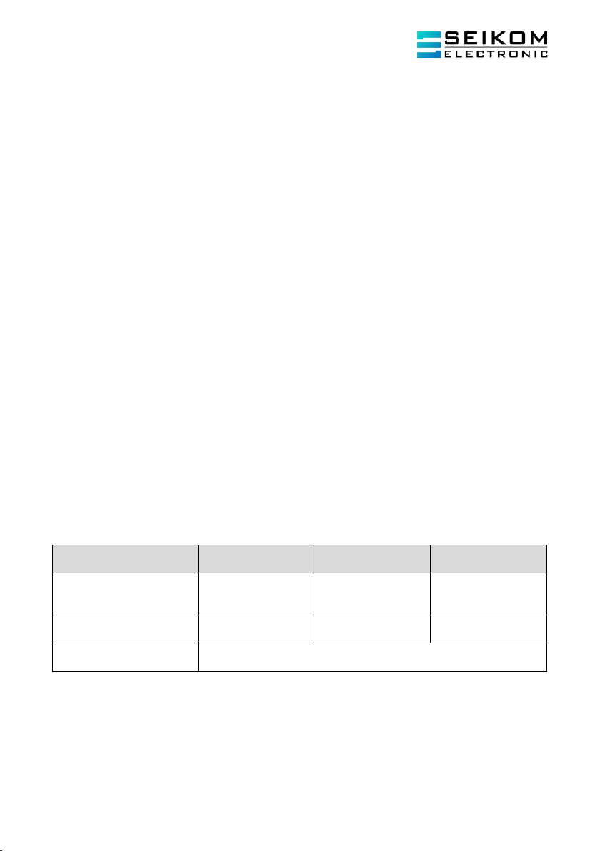
Activity
Monthly visual
inspection
Close inspection
every 6 month
Detailed inspection
every 12 month
Visual check of the sensors
regarding damage, removal
of accumulated dust
●
Inspection regarding
intactness and function
●
Inspection of the entire
facility
Responsibility of the operator
Polluted air flow sensors shall only be cleaned in lukewarm soapy water. Before reinstallation the
sensors should be air-dried completely. Never use hard or sharp objects (e. g. screwdriver, steel
brush) for cleaning.
User Manual
NLSW®75-A Ex (Gg) & Sensor F3.x Ex
Page 12
+49 2058 2044 •info@seikom-electronic.com •www.seikom-electronic.com
5. TROUBLESHOOTING
Products used in areas exposed to explosion hazards cannot be altered or modified. Repair of the
product can only be performed by qualified and authorised personnel which has received
specialised education in this field.
Problem
Cause
Solution
NLSW®75-A Ex does not
work
No or wrong supply voltage
Check supply voltage and
connection
NLSW®75-A Ex cannot
identify flow
Sensor not installed correctly or
the measured range does not
correspond to the technical
data
Check installation conditions
and installation
NLSW®75-A Ex shows
changed behaviour
Sensor is polluted
Clean the sensor with lukewarm
soapy water
NLSW®75-A Ex switches in
case of fast temperature
increase
The temperature gradient
exceeds the technical data
Re-adjust switchpoint /
reinforcement / zero point
6. DISPOSAL
The disposal of the packaging materials and used parts must be in accordance with the national
regulations relevant in the location of operation of the product.
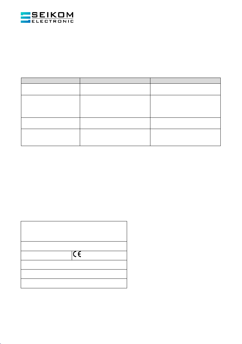
7. LABELLING OF THE AIR FLOW SENSORS F3.X EX
Every air flow sensor of the series F3.x Ex carries a readable label which specifies the required
explosion protection class as specified below. The label cannot be removed. Generally, a readable
identification of the required explosion protection class in field use must be attached before the first
use of the product.
SEIKOM-Electronic GmbH & Co.KG
Fortunastraße 20
D-42489 Wülfrath
Type: F3.x Ex
[Serial number]
[Year of construction]
TFR: 18 ATEX 0003
EII 3G Ex ic IIC T4 Gc
0 °C ≤Ta ≤60 °C
A sensor, that was once used in a not intrinsically safe electric circuit, cannot be used in intrinsically
safe electric circuits subsequently.

User Manual
NLSW®75-A Ex (Gg) & Sensor F3.x Ex
+49 2058 2044 •info@seikom-electronic.com •www.seikom-electronic.com
Page 13
8. GENERAL DESCRIPTION NLSW®75-A EX
With this air flow monitor, you can depict air flows via an externally connected display or realize a
min-max-control via a limiting value transmitter. The monitor also has a continuously adjustable
change-over contact. You can adjust the analog outputs by setting 0V in the absence of flow and
10 V at maximum flow (20 mA). The switch-point of the output relay can be adjusted in the range of
0 …10 V.
9. TECHNICAL DATA OF THE AIR FLOW MONITORS NLSW®75-A EX
Type
NLSW®75-A Ex
Article-No.
70789Ex/DC
70789Ex/AC
60620Ex
Operating voltage
24 V DC
24 V AC
230 V AC
Voltage tolerance
± 5%
Overvoltage category
II
Signal display, voltage
Green LED
Max. power
consumption.
5 VA
Permissible ambient
temperature
-20°C … 50°C
Signal output flow
1 change-over contact
Switch function in case
of flow
Relay contact changes
Current and contact
rating
250 V AC, 6 A, 1,5 kVA
Signal display flow
Yellow LED
Analog outputs
0 …10 V / 4 …20 mA relative
Burden
200 Ω
Applicable range of
media temperature
0°C … 60°C
Switch-point
Adjustable via potentiometer
Measurable range
Adjustable via potentiometer, 0,5m/s… 20.0 m/s
Flow sensors
F3Ex, F3.1Ex, F3.2Ex, F3.3Ex
Z-Barrier
2 pcs. included in delivery
Electrical connection
16 clips, 2.5 mm²
Protection class casing
IP20
Protection class clips
IP20
Casing
Standard housing N75
Casing dimensions
(L x W x H)
112 mm x 75 mm x 73 mm
Mark of conformity

User Manual
NLSW®75-A Ex (Gg) & Sensor F3.x Ex
Page 14
+49 2058 2044 •info@seikom-electronic.com •www.seikom-electronic.com
10. INSTALLATION OF THE AIR FLOW MONITORS NLSW®75-A EX
The air flow monitors of the series NLSW®75-A Ex must be mounted together with the safety barriers,
outside of the area exposed to an explosion hazard. The protection class IP20 of the housing must be
considered.
Connection and start-up must be conducted by qualified personnel. The mandatory competence of
qualified personnel includes knowledge of the types of ignition protection as well as provisions and
regulations concerning equipment in ex-zones! Verify whether the classification (according to these
instructions and the labelling of the devices) is sufficient for the dedicated use.
The housing enables mounting on a profile rail NS35/7,5 according to DIN EN 50022-35. If the profile
rail is exposed to larger vibrations, it has to be mounted in a vibration-reducing manner. Please
follow the provisions of DIN EN 60034-14 (IEC34-14).
Furthermore, the following points must be considered:
a) For the installation of an intrinsically safe electrical circuit a block diagram (system
description) is required, which must be supplied by the builder or operator
b) The installation can only be conducted in a cleared status
c) The start-up can only be performed after the mounting and electrical connection have
been finished
d) The permissible ambient conditions specified in this operating instruction cannot be
exceeded
ATTENTION: It is not permitted to connect the connection “N” of the supply voltage
with b2 (strand no. 2) of the sensor wire when using a 24 AC and DC air flow monitor of
the series NLSW®75-A Ex!
10.1 Commissioning and switch-point adjustment
The relation between air flow velocity and resistance change is non-linear. In the lower section
(small flow) the change of resistance is large. The change of resistance becomes smaller with
constant increase of them flow velocity in the upper section. This characteristic should be
considered when adjusting the switch-point. Moreover, the following requirements must be taken
into account:
Small changes of flow in the high section of flow velocity: The switch-point must be chosen
close to the usual value of the flow, because the changes of the measured value are very small with
changing flow. Since the temperature compensation lags behind the real change of temperature,
such a kind of switch-point adjustment is only possible in use cases with slow temperature change.
Small changes of flow in the small section of flow velocity: The switch-point can be selected
with a certain distance to the usual value of the flow, since changes in the measured value are large
for changing flow. Temperature changes are not influencing the switching behavior.
Large changes of flow: In this case a yes/no response is desired (e. g. to verify that a fan is working
or not).Therefore a large interval may be selected, so that neither temperature changes nor
turbulences may impact the switching behavior.

User Manual
NLSW®75-A Ex (Gg) & Sensor F3.x Ex
+49 2058 2044 •info@seikom-electronic.com •www.seikom-electronic.com
Page 15
For the start-up the following approach is recommended:
1. Install the air flow sensor and monitor according to the instructions.
2. Connect analog measuring equipment.
3. Set potentiometer “Reinforcement” to minimum sensitivity (left stop).
4. Switch Supply voltage; the green LED lights up and the device is ready to operate within
two seconds.
5. Without flow, adjust the the output voltage or current with potentiometer “Zero Point” to
0V or 4mA.
6. Activate the flow generation.
7. At maximum flow, adjust the output voltage or current to 10V or 20mA with
potentiometer “Reinforcement”.
8. Turn the potentiometer „switch-point“ slowly towards maximum until the yellow LED
lights up and the potential-free switcher operates; in order to obtain stable switching
conditions the potentiometer “airflow” should be turned slightly over the switch-point.
9. Review the settings: In order to review the settings turn the air flow off, the yellow LED
extinguishes, the potential-free switcher operates, activate the air flow, the yellow LED
lights up, the potential-free switcher operates again.
The air flow monitor is now adjusted to monitoring function.
Please find the relation between air flow and switching position of the potential-free switcher below:
Flow ≥Threshold value
Signal output switches
Yellow LED „airflow“ lights up
Flow < Threshold value
Signal output does not operate
Yelow LED „airflow“ does not light up
Please do not hesitate to contact us in case of questions or problems.
Technical development and errors reserved, Revision status: 01/2021
User Manual
NLSW®75-A Ex (Gg) & Sensor F3.x Ex
Page 16
+49 2058 2044 •info@seikom-electronic.com •www.seikom-electronic.com
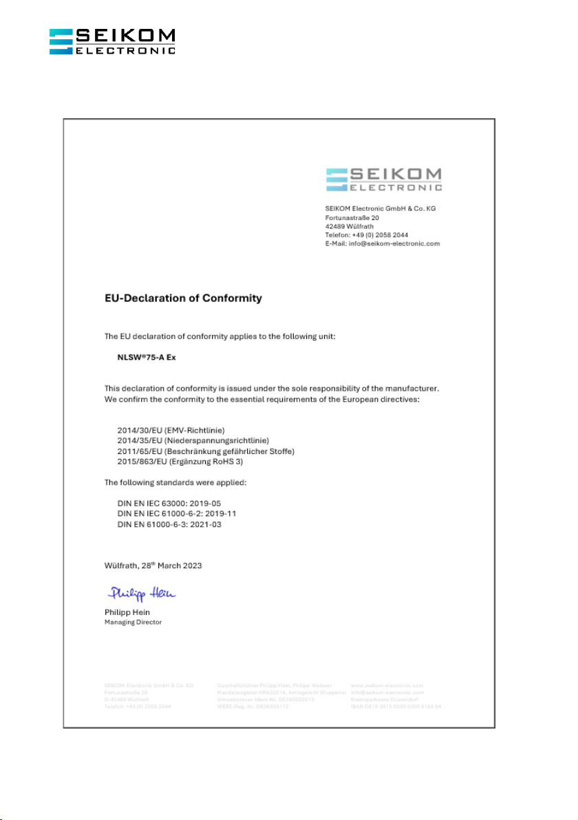
11. EU DECLARATION OF CONFORMITY

User Manual
NLSW®75-A Ex (Gg) & Sensor F3.x Ex
+49 2058 2044 •info@seikom-electronic.com •www.seikom-electronic.com
Page 17

Page 18
+49 2058 2044 •info@seikom-electronic.com •www.seikom-electronic.com
Wachsendes Netz lokaler Vertriebshändler online verfügbar
www.seikom-electronic.com
Unser Produktportfolio
Strömung
Temperatur
Druck
Luftqualität und CO2
Zener Barrieren
Universal Transmitter
+49 2058 2044
info@seikom-electronic.com
www.seikom-electronic.com
SEIKOM-Electronic GmbH & Co. KG
Fortunastraße 20
42489 Wülfrath
This manual suits for next models
1
Table of contents
Popular Security Sensor manuals by other brands


Honeywell
Honeywell Fire-Lite Alarms SD365T Installation and maintenance instructions

ZKTeco
ZKTeco LD01 user manual

Buckingham
Buckingham 2139 ASSEMBLY & ATTACHMENT INSTRUCTIONS

B.E.G.
B.E.G. LUXOMAT Indoor 180/R-2W UK Operating and mounting instructions

SECO-LARM
SECO-LARM Enforcer series manual

Hytronik
Hytronik HC403VRC-KD Installation and instruction manual


