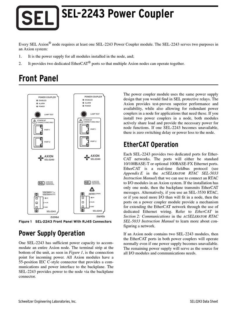
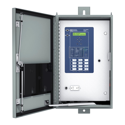
Sel SEL-2600 User manual

Date Code 20000525 SEL-2600 RTD Module
SEL-2600 RTD Module
Instruction Manual
Features & Benefits
Transmit 12 RTD-based temperature measurements and a single contact status
up to 500 meters using inexpensive fiber-optic cable with the SEL-2600 RTD
Module. The SEL-2600 connects directly to the SEL-701 Motor Relay using fiber-
optic connectors built into each device and also connects to the SEL-2030 Commu-
nications Processor using a single SEL-2800 Fiber-Optic Transceiver. The fiber-
optic link eliminates expensive cable pulls and provides electrical noise immunity
and ground isolation.
➤Measure up to 12 RTD temperatures plus one contact input with
zero settings.
➢100-ohm platinum
➢100-ohm nickel
➢120-ohm nickel
➢10-ohm copper
➤LEDs indicate device status, transmit status, and contact
input status.
➤Power from 120 Vac or 240 Vac.
➤Operates in extreme ambient temperatures from –40º to +85ºC.

SEL-2600 RTD Module Date Code 20000525
Initial Checkout
2
Initial Chec out
Step 1. Connect Terminal 26 to an appropriate ground.
Step 2. Apply line power to the SEL-2600 at Terminals 23 and 24
(120 Vac) or Terminals 23 and 25 (240 Vac).
The SEL-2600 will power up and perform internal diagnostics.
The module is ready when the green ENABLE LED illuminates.
Step 3. Verify the red TX LED pulses twice per second. Each pulse
corresponds to the transmission of RTD data, device status, and
contact input status.
Step 4. Connect Terminal 20 to Terminal 21 to test the contact input. The
red INPUT LED illuminates when the contact input is electrically
shorted.
Step 5. SEL-701 Motor Relay Application
➢Connect the SEL-2600 to the SEL-701 Motor Relay as
shown in Figure 1 on page 4. Set the relay as directed in
SEL-701 Motor Relay Application on page 4.
NOTE: The SEL-701 front panel may display “RTD Fail re” if the correct RTDs are not
yet connected. The SEL-701 METER T report displays the RTD temperat re as
“Comm Fail” if the fiber connection is not operating properly.
SEL-2030 Communications Processor Application
➢Connect the SEL-2600 to the SEL-2030 Communications
Processor as shown in Figure 2, Figure 3, or Figure 4 on
page 7. Set the SEL-2030 as directed in SEL-2030 Communi-
cations Processor Applications on page 6.
Step 6. Follow the wiring diagram in Figure 5 on page 13 to connect
RTDs to the SEL-2600.
NOTE: If RTDs are not available, test the SEL-2600 RTD inp ts by connecting all
three terminals for each RTD together. For example, sing two short wires, con-
nect Terminals 01, 02, and 03 together. The SEL-701 METER T report displays the
corresponding temperat re as “Short.” The SEL-2030 stores the hexidecimal
val e 8000h in the corresponding data register.

Date Code 20000525 SEL-2600 RTD Module
Installation 3
Installation
Step 1. Locate an appropriate mounting panel or enclosure near the
protected device.
Step 2. Drill four mounting holes (see Figure 6 on page 14).
Step 3. Secure the SEL-2600 using the four bolts and locknuts provided.
Step 4. Ground the SEL-2600 by connecting Terminal 26 to an
appropriate electrical ground.
Step 5. Connect as many as 12 RTDs to the SEL-2600 terminal blocks
(see Figure 5 on page 13).
Step 6. Record the type and location of each RTD in Table 1 on page 4.
Step 7. Connect a dry contact to the SEL-2600 contact input Terminals 20
and 21 as appropriate.
!CAUTION: Do not connect ac or dc voltage to the contact inp t.
Step 8. SEL-701 Motor Relay Application
➢Connect the SEL-2600 to the SEL-701 Motor Relay using a
single fiber-optic cable (SEL part number C801FZ or
C801FD). Follow the SEL-701 setting instructions in
SEL-701 Motor Relay Application on page 4.
SEL-2030 Communications Processor Application
➢Connect the SEL-2600 to the SEL-2030 Communications
Processor using a single fiber-optic cable and a fiber-optic
transceiver as outlined in SEL-2030 Communications Proces-
sor Applications on page 6.
Step 9. Connect ac line power to the SEL-2600 through Terminals 23 and
24 (120 Vac) or Terminals 23 and 25 (250 Vac). The green
ENABLE LED illuminates when ac power is applied and the
internal diagnostics are complete.
Step 10. Verify the SEL-2600 is operating properly.
➢The green ENABLE LED is illuminated.
➢The red TX LED pulses twice per second.
➢The red INPUT LED illuminates when the SEL-2600 contact
input is energized.
➢The SEL-701 or SEL-2030 receives valid RTD measure-
ments.

SEL-2600 RTD Module Date Code 20000525
SEL-701 Motor Relay Application
4
Table 1 RTD Type and Location Worksheet.
SEL-701 Motor Relay Application
The SEL-701 Motor Relay provides comprehensive motor protection, includ-
ing short circuit, load loss, load jam, and frequent starting protection as well as
unbalance current and phase reversal protection. The patented motor thermal pro-
tection element used by the SEL-701 Motor Relay accurately tracks the heating
effects of overloads and unbalance current.
Combining the SEL-2600 and the SEL-701 Motor Relay enhances this list of
protection features by adding remote RTD-based thermal protection.
Figure 1 Motor Protection with the SEL-701 Motor Rel y.
T ble 1 RTD Type nd Loc tion Worksheet
RTD Input RTD Loc tion RTD Type
RTD1
RTD2
RTD3
RTD4
RTD5
RTD6
RTD7
RTD8
RTD9
RTD10
RTD11
RTD12
Motor Load
SEL-2600 SEL-701
Relay
Fiber-Optic Ports
(b ilt into SEL-2600 & SEL-701)
Up to 500 meters via
single fiber-optic cable,
SEL
p
art n mber C801FD
Up to 12 RTD inp ts, pl s
one contact (speed switch, etc.)

Date Code 20000525 SEL-2600 RTD Module
SEL-701 Motor Relay Application 5
Step 1. Connect the SEL-2600 to the SEL-701 Motor Relay using fiber-
optic cable C801FD. Connect the cable between the SEL-2600
Fiber-Optic TX output and the SEL-701 Motor Relay Fiber-Optic
RX input.
Step 2. Set the SEL-701 Motor Relay to accept the RTD temperature data
packets (see Data Packet Definition on page 11) sent by the
SEL-2600. You can use any of the following three methods to
enter the settings.
➢Relay front-panel menus: Set Relay\Relay Elements\RTD
CONFIGURATION.
➢Personal computer connected to the relay serial port, running
SEL-701PC software.
➢Personal computer connected to the relay serial port, using a
terminal emulation software package.
In the SEL-701 Relay, set the RTD Input Option setting
(RTDOPT) equal to EXT. This enables use of the external module
data. Set the RTD Location and RTD Type settings based on the
information you recorded in Table 1 on page 4. Finally, set the
RTD Alarm and Trip Temperature settings as required for your
application.
Refer to the SEL-701 Motor Relay Instruction Manual for more
details regarding calculation and entry of these settings.
Step 3. After accepting the relay settings, verify correct RTD temperature
measurement using one of these methods.
➢Relay front-panel menus: Meter Values\Thermal & RTD
Data.
➢Personal computer connected to the relay serial port, running
SEL-701PC software.
➢Personal computer connected to the relay serial port, using a
terminal emulation software package and the METER T
command.
The relay will indicate the temperatures of each connected,
healthy RTD. If the relay reports that an RTD is open or shorted,
or if the temperature reading is wrong, verify the wiring at the
SEL-2600. Also verify the RTD type connected to that input
matches the RTD type setting.

SEL-2600 RTD Module Date Code 20000525
SEL-2030 Communications rocessor Applications
6
SEL-2030
Communications Processor Applications
Use the SEL-2600 RTD Module in combination with the SEL-2030 Commu-
nications Processor to enhance many protection and monitoring applications. The
SEL-2030 monitors temperature data from the SEL-2600, performs threshold com-
parisons, and sends control commands to a protective relay.
The applications shown in Figure 2, Figure 3, and Figure 4 on page 7 repre-
sent a few of the possible configurations using the SEL-2600 and the SEL-2030.
Contact SEL for help in applying these products in other configurations.
Program the SEL-2030 to perform four automated steps:
Step 1. Receive temperature data from the SEL-2600.
Step 2. Store the temperature data in memory.
Step 3. Perform temperature threshold comparisons.
Step 4. Issue control commands to a protective relay based on the
temperature comparisons.
The next few pages describe how to configure the SEL-2030 to perform the
four automated steps shown above. It is assumed that the SEL-2600 is connected to
Serial Port 4 of the SEL-2030. Refer to the SEL-2030 Communications Processor
Reference Manual and the SEL-2030 Communications Processor User’s Guide for
further information on programming concepts.
Receive Temperature Data
Connect the SEL-2600 to the SEL-2030 using an SEL-2800 Fiber-Optic
Transceiver and fiber-optic cable C801FD. Set the port settings of the SEL-2030
as shown.
SET P 4
DEVICE = S
CONFIG = N
PORTID = SEL-2600 RTD Module
BAUD = 2400
DATABIT = 8
STOPBIT =
PARITY = N
RTS_CTS = N
XON_XOFF= N
TIMEOUT = OFF

Date Code 20000525 SEL-2600 RTD Module
SEL-2030 Communications rocessor Applications 7
Figure 2 Motor Protection with the SEL-501 Rel y.
Figure 3 Gener tor Protection with the SEL-300G Rel y.
Figure 4 Tr nsformer Protection with the SEL-587 or SEL-387 Rel y.
SCADA
EIA-232
PC/HMI
SEL-2800
Fiber-Optic Transceiver
SEL-2030
Comm nications Processor
SEL-501 Relay SEL-2600
RTD Mod le
Motor Load
EIA-232
SCADA PC/HMI
SEL-2800
Fiber-Optic Transceiver
SEL-2030
Comm nications Processor
SEL-300G Relay SEL-2600
RTD Mod le
Generator Prime
Mover
Transformer
SCADA
EIA-232
PC/HMI
SEL-2800
Fiber-Optic Transceiver
SEL-2030
Comm nications Processor
SEL-587/387 Relay SEL-2600
RTD Mod le

SEL-2600 RTD Module Date Code 20000525
SEL-2030 Communications rocessor Applications
8
Store Temperature Data in SEL-2030 Memory
Use the SET A command to reserve memory.
SET A 4
AUTOBUF = N
STARTUP =""
SEND_OPER= N
REC_SER = N
MSG_CNT = 0
ARCH_EN = N
USER = 54
The USER setting reserves a data region with 54 registers. Each register is
2 bytes for a total length of 108 bytes. This data region holds the received data
packet and mathematical equations for threshold comparisons.
The SEL-2030 automatically moves the data section of each received data
packet (see Table 3 on page 11) into the reserved USER data region at the addresses
shown in Table 2 on page 9.
The SEL-2600 data packet includes temperature information for each of the
four types of RTDs. To access the correct temperature, use the memory map loca-
tion associated with the correct RTD type.
Data from the USER region can be accessed using an absolute address or in
the form “n:USER:offset”where ‘n’is the port number and ‘offset’is the value
shown in the offset column of Table 2 on page 9. For example, access the RTD 2,
10-ohm copper data using the absolute address F80Ah or the offset form:
“4:USER:0Ah”. The examples in the remainder of this section use the offset form.
Perform Temperature Threshold Comparisons
The example SEL-2030 settings shown below compare the measured
temperature of RTD 2 (10-ohm copper) against a threshold of 28C. If the measured
temperature is valid (i.e., the RTD is not shorted or open) and is above the thresh-
old, Bit 0 of register 035H is set to ‘1’. Serial Port 4 is again assumed.
SET M 4
033h = 28 #Store temp threshold
2 034h = 4:USER:033h #Get the threshold
3 034h -= 4:USER:0Ah #Subtract the RTD temp
4 035h:0 = 4:USER:034h: 5 #Get sign bit of result
5 035h:0 *= !4:USER:0Ah: 5 #Test bit 5 of temp
6 035h:0 *= !4:USER:0Ah: 4 #Test bit 4 of temp
The text following the pound (#) symbols are comments and are not required
to set the SEL-2030.
Line 1: Stores the temperature threshold in register 033h.
Line 2: Copies the threshold to register 034h in preparation for Line 3.

Date Code 20000525 SEL-2600 RTD Module
SEL-2030 Communications rocessor Applications 9
Line 3: Subtracts the measured RTD temperature from the threshold and
stores the result in register 034h. If the result is negative, the mea-
sured RTD temperature is above the threshold and Bit 15 (the sign
bit) of 034h is set.
Line 4: Copies the sign bit (Bit 15) of 034h into Bit 0 of 035h.
Line 5: Clears Bit 0 of 35h if RTD is shorted.
Line 6: Clears Bit 0 of 35h if RTD is open.
Table 2 SEL-2030 Communication s Processor M emory Map
This logic can be expanded to operate on additional RTDs. Use the SET A
command to reserve additional registers for mathematical equations.
SET A USER 4
USER = 57
T ble 2 SEL-2030 Communic tions Processor Memory M p
Address (hex) Offset D t Description
F800h–F801h 0–01h Milliseconds since device power-up
F802h 02h Device status
F803h 03h RTD 1, 100-ohm platinum
F804h 04h RTD 1, 100-ohm nickel
F805h 05h RTD 1, 120-ohm nickel
F806h 06h RTD 1, 10-ohm copper
F807h 07h RTD 2, 100-ohm platinum
F808h 08h RTD 2, 100-ohm nickel
F809h 09h RTD 2, 120-ohm nickel
F80Ah 0Ah RTD 2, 10-ohm copper
•
•
(this 4-register sequence is repeated for RTD 3 through RTD11)
•
•
F82Fh 2Fh RTD 12, 100-ohm platinum
F830h 30h RTD 12, 100-ohm nickel
F831h 31h RTD 12, 120-ohm nickel
F832h 32h RTD 12, 10-ohm copper
F833h–F835h 33h–35h Storage for mathematical functions

SEL-2600 RTD Module Date Code 20000525
SEL-2030 Communications rocessor Applications
10
Use the SET M command to add the equations. The following settings show
how to add RTD 12, 100-ohm platinum (4:USER:02Fh) at a threshold of 31C.
SET M 4
7 036h = 3 #Store temp threshold
8 037h = 4:USER:036h #Get the threshold
9 037h -= 4:USER:02Fh #Subtract the RTD temp
0 038h:0 = 4:USER:037h: 5 #Get sign bit of result
038h:0 *= !4:USER:02Fh: 5 #Test bit 5 of temp
2 038h:0 *= !4:USER:02Fh: 4 #Test bit 4 of temp
Issue Control Commands to Relay
Connect the SEL-2030 to the protective relay. Establish communications as
outlined in the SEL-2030 Communications Processor Reference Manual and the
protective relay’s instruction manual.
Use the SET P command to set AUTO_CONFIG to “Y.”This enables auto-
matic control capabilities for the serial port connected to the relay. Use the SET A
command to set SEND_OPER to “Y.”This enables fast operate commands based
on logic bit transitions. Use the SET L command to control four breakers using fast
operate commands based on the result of a single temperature comparison.
The following example settings assume the relay is connected to SEL-2030
Serial Port 10, and the SEL-2600 is connected to Serial Port 4.
SET L 0
SBR = 4:USER:35h:0 #If above threshold open breaker
CBR = 0
SBR2 = 4:USER:35h:0 #If above threshold open breaker 2
CBR2 = 0
SBR3 = 4:USER:35h:0 #If above threshold open breaker 3
CBR3 = 0
SBR4 = 4:USER:35h:0 #If above threshold open breaker 4
CBR4 = 0
The example can be modified to control each breaker based on separate tem-
perature thresholds. The section titled Perform Temperature Threshold Compari-
sons on page 8 shows how to program the SEL-2030 for multiple temperature
comparisons. The following settings use the results of those comparisons to control
Breakers 1 and 2.
SBR = 4:USER:35h:0 #If RTD 2 > 28 degrees C open breaker
CBR = 0
SBR2 = 4:USER:38h:0 #If RTD 2 > 3 degrees C open breaker 2
CBR2 = 0
Refer to the specific protective relay’s instructional manual for more informa-
tion on fast operate commands, relay wiring, and relay configuration.

Date Code 20000525 SEL-2600 RTD Module
Data acket Definition 11
Data Pac et Definition
The SEL-2600 RTD Module sends a binary data packet every 0.5 seconds. The
packet contains data for all four types of supported RTDs so no settings are required
in the SEL-2600 (patent pending). Using the SEL-2800 Fiber-Optic Transceiver,
any EIA-232 device can be configured to understand the binary data packet con-
tents shown in Table 3.
Table 3 SEL-2600 RTD Module Data Packet Definition
T ble 3 SEL-2600 RTD Module D t P cket Definition
D t
V lue
D t
Size
Description
A546h 2 bytes Beginning of Message Code
74h 1 byte Message Length (116 bytes)
0000000000h 5 bytes Routing Value (0)
00h 1 byte Status Byte
12h 1 byte Function Code
00h 1 byte Sequence Byte
00h 1 byte Pad Byte
xxxxxxx 4 bytes
Milliseconds Since SEL-2600 Power-Up
or Clock Rollover (86,400,000 ms/5265C00h)
xx 2 bytes Device Status (Bitmap)
Bit 0: Power Supply Status
Bit 1: RTD Circuitry Status
(0 = okay; 1 = fail)
Bit 2: Watchdog Timer Status
(0 = okay; 1 = fail)
Bit 3: 8 V Power Supply Status
(0 = okay; 1 = fail)
Bit 4: 5 V Power Supply Status
(0 = okay; 1 = fail)
Bit 5: –5 V Power Supply Status
(0 = okay; 1 = fail)
Bits 6–14: Unused, Zero
Bit 15: Contact Input State
(0 = deasserted; 1 = asserted)
xxxx 96 bytesaTemperature Data (
C)
Word One: PT100 temperature
Word Two: NI100 temperature
Word Three: NI120 temperature
Word Four: CU10 temperature
(Continued)

SEL-2600 RTD Module Date Code 20000525
SEL-2600 Guideform Specifications
12
SEL-2600 Guideform Specifications
RTD (Resistive Temperature Device) monitoring shall be provided by a
microprocessor-based module with the following characteristics.
➤Module shall be capable of acquiring RTD data from as many as
12 RTDs.
➤Module shall accept input from any of four different types of
three-wire RTDs (100-ohm platinum, 100-ohm nickel, 120-ohm
nickel, and 10-ohm copper) on every RTD input terminal.
➤Module shall accept a single contact input.
➤Module shall require no configuration settings.
➤Module shall perform internal self-tests on the power supply and
RTD inputs.
➤Module shall transmit over fiber optics all measured RTD values,
input contact status, and self-test status at 500 ms intervals over a
distance of 500 meters.
➤Module shall secure data communications using CRC-16 (Cycli-
cal Redundancy Check) error detection.
➤Module shall be equipped with a fiber-optic port.
➤Module shall use LEDs (Light Emitting Diodes) to indicate device
self-test status, input contact status, and fiber port transmit status.
➤Module shall be capable of operating within specification over a
temperature range of –40°to +85°C.
➤Module shall be line powered by 120 Vac or 240 Vac.
➤Module shall mount to a flat surface and have package dimensions
not exceeding 9.500" x 4.418" x 2.060".
T ble 3 SEL-2600 RTD Module D t P cket Definition
(Continued)
D t
V lue
D t
Size
Description
Four words are sent for each of the 12 inputs.
Use only the appropriate temperature for the type
of RTD connected to each input.
If an RTD circuit is open, the error code 7FFFh
is sent; if the circuit is shorted, the error code
8000h is sent. For the first four seconds after
power is applied to the module, it sends the
error code 7FF0h.
yy 2 bytes CRC-16 Data Block Check Code
a 2 bytes er word • 4 words er RTD • 12 RTDs = 96 bytes.

Date Code 20000525 SEL-2600 RTD Module
Wiring Diagram 13
Wiring Diagram
Figure 5 SEL-2600 Wiring Di gr m.
N=Neutral, N/C=No Connection, RTN=Return.
01
02
03
04
05
06
07
08
09
10
11
12
13
14
15
16
17
18
19
20
21
22
+
—
RTN
+
—
RTN
+
—
RTN
+
—
RTN
+
—
RTN
+
—
RTN
N/C
IN+
IN—
N/C
120
Vac
+
N
N/C
23
24
25
26
+
N/C
N
240
Vac
RTD1 RTD2 RTD3 RTD4 RTD5 RTD6 CONTACT INPUT AC POWER
27
28
29
30
31
32
33
34
35
36
37
38
39
40
41
42
43
44
+
—
RTN
+
—
RTN
+
—
RTN
+
—
RTN
+
—
RTN
+
—
RTN
RTD7RTD8RTD9RTD10RTD11RTD12
LEDs
ENABLE
INPUT
TX
Speed switch
or other contact
+120 or 240 Vac
120 Vac Ne tral
240 Vac Ne tral

SEL-2600 RTD Module Date Code 20000525
Mechanical Diagram
14
Mechanical Diagram
Figure 6 SEL-2600 Mech nic l Di gr m.
φ0.203"
(φ5.16 mm)
4.418"
(112.22 mm)
Top View
End View
9.000"
(228.60 mm)
1.750"
(44.45 mm)
8.515"
(216.28 mm)
9.500"
(241.30 mm)
2.060"
(52.32 mm)
0.620"
(15.75 mm)

Date Code 20000525 SEL-2600 RTD Module
Specifications 15
Specifications
12 RTD Inputs
Measuring Range: –50
to +250
C
Error: ±0.5
C, typical
±2°C, maximum
Open and short circuit detection.
PT100, NI100, NI120,
and CU10 RTD-types supported.
Contact Input
One dry contact input.
Use for local speed switch or other monitoring.
Communication
Binary data packet
contains temperatures,
contact status, self-test results.
Sent twice per second at 2400 baud.
CRC-16 data security.
Up to 500 m using fiber-optic cable C801FD.
ower Supply
120 Vac, 50/60 Hz
240 Vac, 50/60 Hz
2 VA total burden
Operating Temperature
–40
to +85
C
–40
to +185
F
Type Tests
Generic Emissions, EN 50081-1: 1992,
Light Industrial:
Generic Immunity, EN 50082-2: 1995,
Heavy Industrial:
Radiated and EN 55022: 1998,
Conducted Class B
Emissions:
Conducted EN 61000-4-6: 1996,
Radio Frequency: 10 Vrms
Radiated Radio ENV 50204: 1996,
Frequency 10/V/m
(900 MHz with
modulation):
Cold: IEC 60068-2-1: 1990,
Test Ad;
16 hr @ –40°C
Dry Heat: IEC 68-2-2: 1974,
Test Bd;
16 hr @ +85°C
Damp Heat, Cyclic: IEC 60068-2-30: 1980,
Test Db,
55°C, 6 cycles,
95% humidity
Dielectric Strength: IEC 60255-5: 1977,
IEEE C37.90: 1989,
3100 Vdc on power
supply, 510 Vac
on contact input
Impulse: IEC 60255-5: 1977,
0.5 J, 5000 V
Vibration: IEC 60255-21-1: 1988,
Class 1
Class 2
Shock and Bump: IEC 60255-21-2: 1988,
Class 1
Class 2
Seismic: IEC 60255-21-3: 1993,
Class 2
1MHz Burst IEC 60255-22-1: 1988,
Disturbance: Class 3
(2500 V common and
differential mode)
Electrostatic IEC 60255-22-2: 1996,
Discharge: EN 61000-4-2: 1995,
Level 4
Radiated Radio IEC 60255-22-3; 1989,
Frequency: IEC 801-3: 1984,
ENV 50140: 1994,
IEEE C37.90.2: 1995,
10 V/m
Fast Transient IEC 60255-22-4: 1992,
Disturbance: EN 61000-4-4: 1995,
Level 4
Surge Withstand: IEEE C37.90.1: 1989,
3000 V oscillatory
5000 V transient
Certifications
ISO: Device is designed
and manufactured to an
ISO-9001 certified quality program.
UL/CSA: UL recognized to the requirements
of UL-508; CSA C22.2, N.14 for Industrial
Control Equipment.
CE: CE Mark.

SEL-2600 RTD Module Date Code 20000525
SCHWEITZER ENGINEERING LABORATORIES
2350 NE Hopkins Court • ullman, WA 99163-5603 USA
hone: (509) 332-1890 • Fax: (509) 332-7990
Internet: www.selinc.com • E-mail: [email protected]
!CAUTION: Do not connect ac or dc voltage to
the contact inp t.
!DANGER: Disconnect power before removing
top cover.
Schweitzer Engineering Laboratories, SELOGIC, and are regis-
tered trademarks of Schweitzer Engineering Laboratories. All brand
or prod ct names appearing in this doc ment are the trademark or
registered trademark of their respective holders. U.S. and Foreign
Patents Pending.
The software (firmware), schematic drawings, mod le commands,
and mod le messages are copyright protected by the United States
Copyright Law and International Treaty provisions. All rights are
reserved. Yo may not copy, alter, disassemble, or reverse-engineer
the software. Yo may not provide the software to any third party.
È
2000 Schweitzer Engineering Laboratories. All rights reserved.
!ATTENTION: Ne pas raccorder de so rce de
tension CA o CC s r le contact d'entrée.
!DANGER: Débrancher l’alimentation avant de
retirer le co vercle d dess s.
R
Notes
Table of contents
Other Sel Control Unit manuals
Popular Control Unit manuals by other brands

TECHCON SYSTEMS
TECHCON SYSTEMS TS924 Set up and operating instructions

BASETech
BASETech 1456297 operating instructions

Emerson
Emerson Fisher 8532 instruction manual

Monacor
Monacor ATT-1950 instructions

oventrop
oventrop Multiblock TQ-RTL Installation and operating instructions

Bosch
Bosch rexroth IH04E Assembly instructions