Sel SEL-387A User manual

Overcurrent Elements Page 1 of 7 20120723
Hands-On Relay Testing Session
Overcurrent Elements
Exercise Objectives
After completing this exercise, you should be able to do the following:
•Identify overcurrent element settings.
•Determine effective overcurrent protection settings.
•Validate relay settings.
In this exercise, the instructor will introduce the SEL-387A Current Differential and Overcurrent Relay
overcurrent elements, determine how to set the elements for transformer backup protection, and
demonstrate how to enter the settings.
You will then enter the overcurrent settings into ACSELERATOR QuickSet®SEL-5030 Software. After
sending your settings to the relay, you will validate the settings and verify the protection scheme.
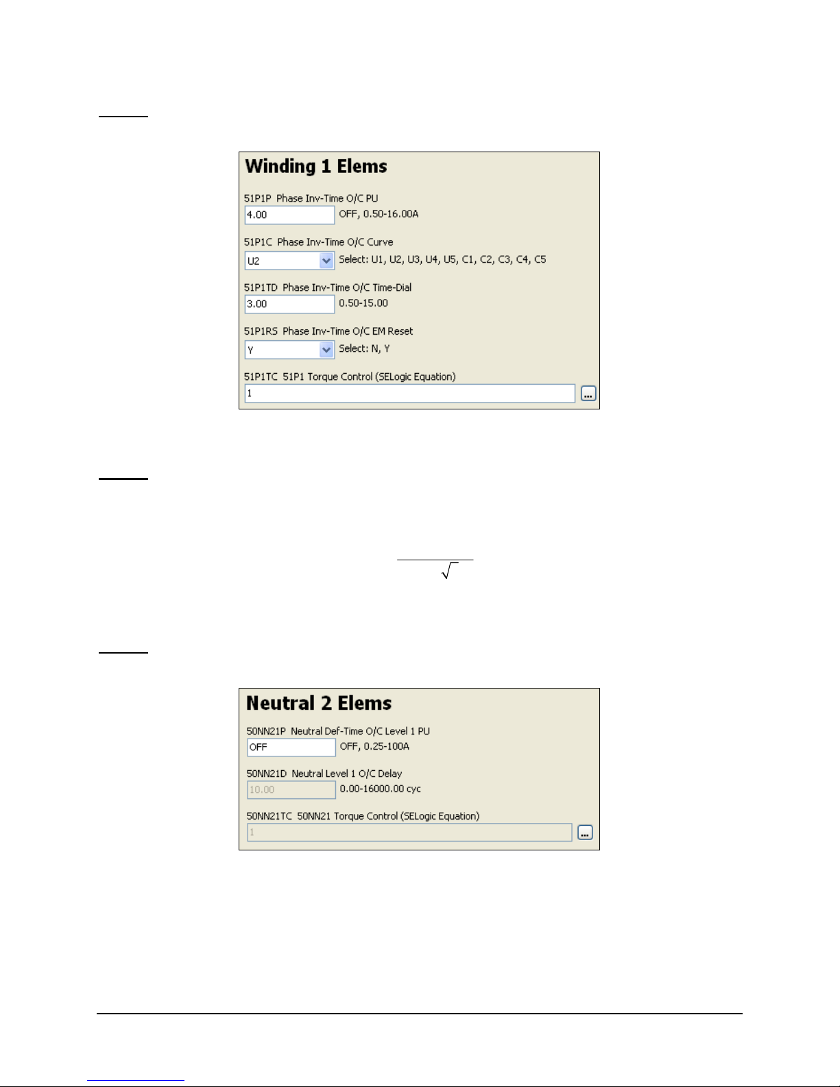
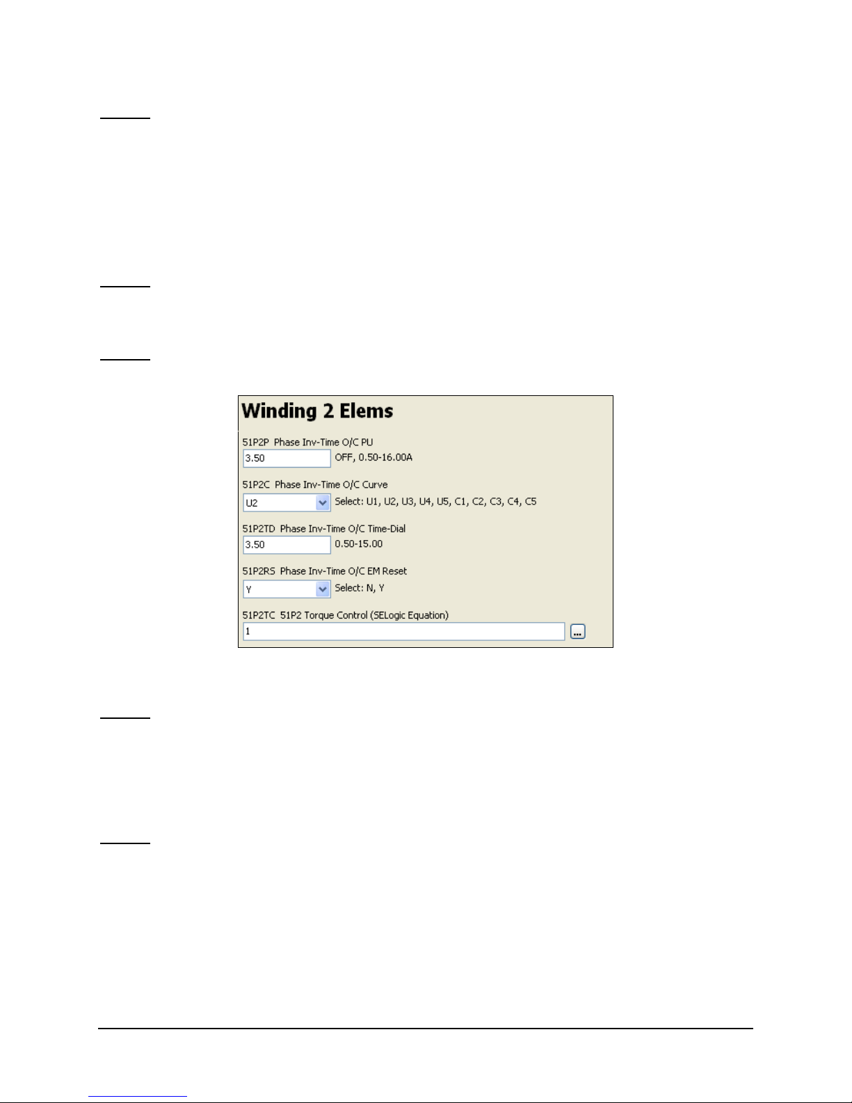
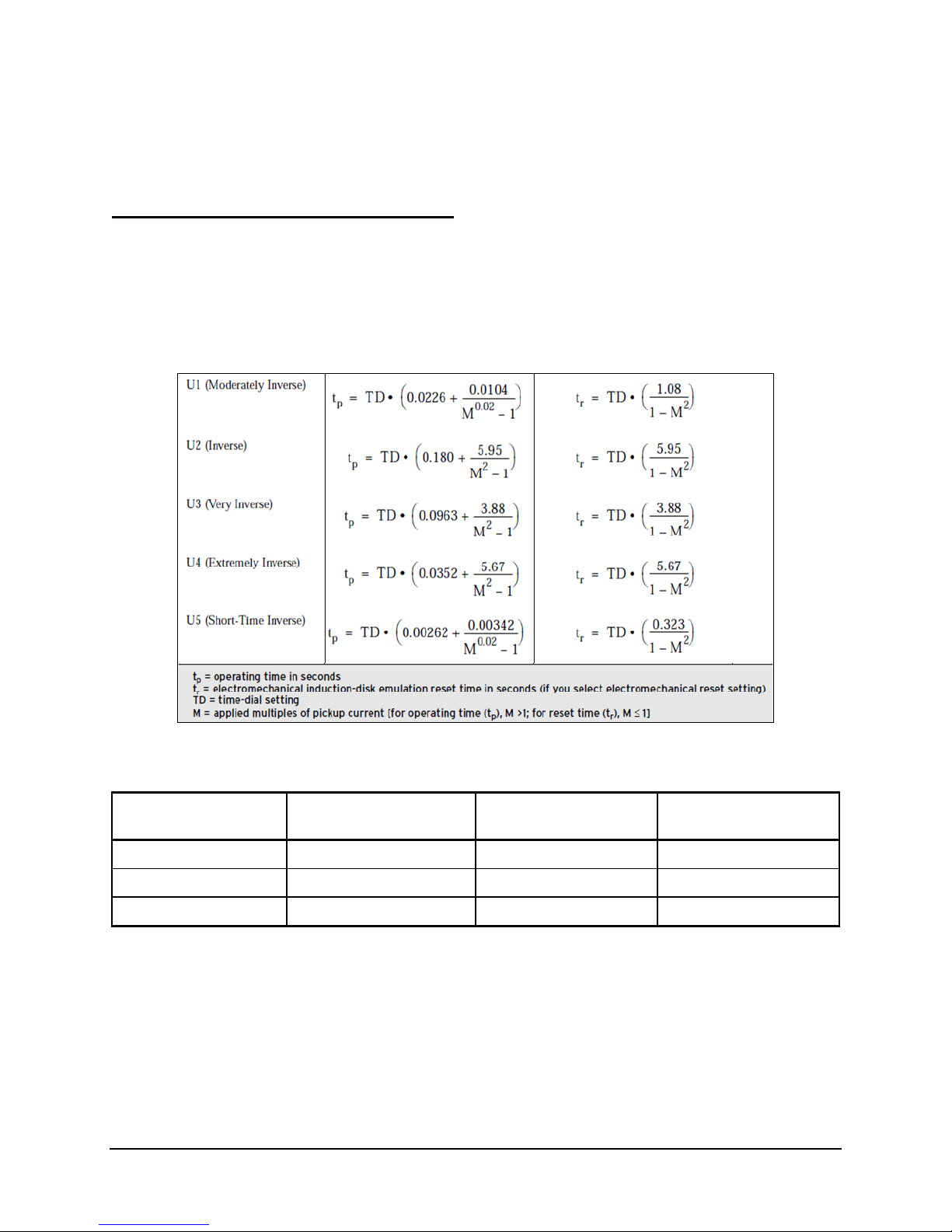
SEL-387A Time-Overcurrent Elements
The SEL-387A provides numerous overcurrent elements, as many as 11 per winding and 5 per neutral
input. Four levels of phase instantaneous or definite-time elements are available for overcurrent
protection, breaker failure protection, overcurrent phase selection for targeting, transformer backup
protection, and so on. Two levels of negative-sequence and residual instantaneous elements provide
protection against unbalanced conditions and ground faults. Phase, negative-sequence, and residual time-
overcurrent elements are available for system backup protection. The SEL-387A also has neutral
instantaneous or definite-time elements available.
For a more detailed description of each of the overcurrent elements, refer to the SEL-387A Instruction
Manual (available at http://www.selinc.com).
Hands-On Activity 1: Enable Overcurrent Elements
In this hands-on activity, you will enable the element for a particular winding and enter settings for
backup overcurrent protection. Write your answers in the space provided.
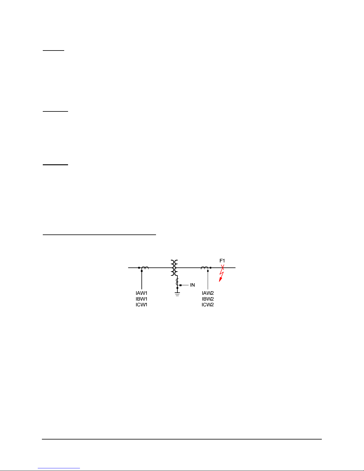
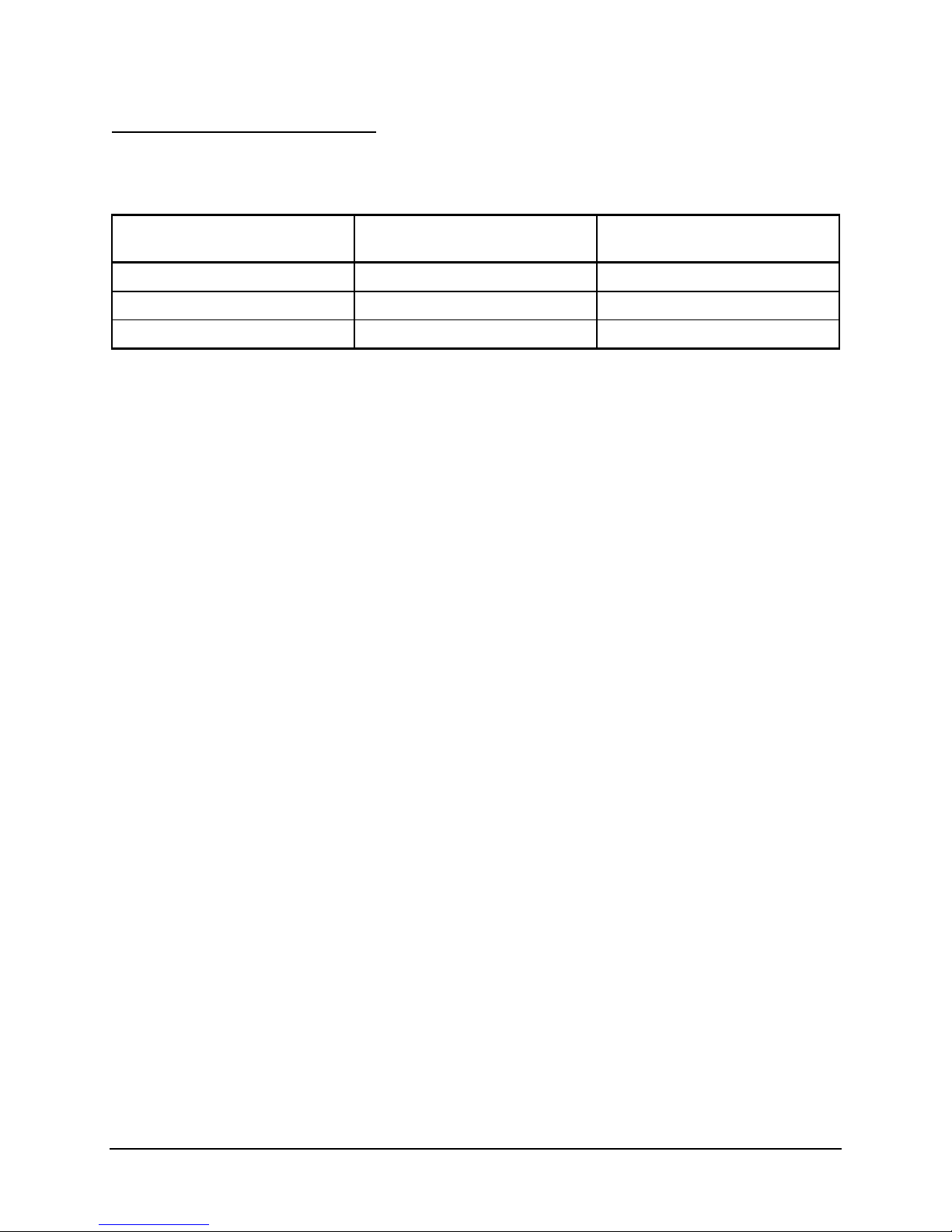
Transformer Data
Rated 50 MVA
Rated high side 161 kV (DAB)
Rated low side 14.4 kV (wye)
High-side bushing current transformer (CT) ratio (wye connected)
Low-side bushing CT ratio (wye connected)
Neutral bushing CT ratio

Overcurrent Elements Page 2 of 7 20120723
Step 1
In ACSELERATOR QuickSet, select Group 1 > Set 1 > Winding 1 Elements.
Figure 1 Phase Time-Overcurrent Element Settings
Step 2
Determine the Winding 1 Max Phase Time Overcurrent Trip Level setting.
51P1P = ________________
The transformer maximum expected load equals MVA •1000
kV • 3
Set the 51P1 pickup to 150 percent of expected maximum load.
Step 3
Select Group 1 > Set 1 > Neutral 2 Elements.
Figure 2 Neutral Instantaneous Overcurrent Element Settings

Overcurrent Elements Page 3 of 7 20120723
Step 4
Determine the Neutral Inst Overcurrent Trip Level setting.
50NN21P = ________________
Set the 50N element to 50 percent of the maximum ground fault current. Obtain the maximum value from
a system fault study.
For this example, assume a 5,000 A ground fault current.
Step 5
Verify that the Neutral Inst Overcurrent Trip Delay (50NN1D) is set at minimum value of 0.50.
Step 6
Select Group 1 > Set 1 > Winding 2 Elements.
Figure 3 Phase Time-Overcurrent Element Settings
Step 7
Determine the Winding 2 Phase Time Overcurrent Trip Level setting.
51P2P = __________________
Set the phase time-overcurrent element to 150 percent of the continuous rated amperes.
Step 8
Set the Winding 2 Phase TOC Curve Selection to coordinate with the downstream time-overcurrent
protection.
51P2C = __________________

Overcurrent Elements Page 4 of 7 20120723
Step 9
Set the Winding 2 Phase TOC Time Dial.
51P2TD = __________________
For this exercise, set the time dial to 3 to provide time coordination with downstream devices. You can
determine the time dial setting based on a fault coordination study.
Step 10
Verify that the following settings are at the default values:
51P2RS = Y
51P2TC = 1
Step 11
Save your settings, and then send them to the relay.
Hands-On Activity 2: Validate Overcurrent Elements
In this hands-on activity, you will validate the phase and neutral instantaneous overcurrent elements and
the phase time-overcurrent elements.
Validation Functional Description
Figure 4 illustrates the location of Fault F1. The relay should operate when the fault magnitude exceeds
the overcurrent relay setting and the time-delay elements time out.
Figure 4 Overcurrent Validation Fault Location

Overcurrent Elements Page 5 of 7 20120723
Validation Pickup Test Values
The instructor will use the SEL-AMS (Adaptive Multichannel Source) to inject secondary quantities into
the relay terminals to simulate faults (as indicated in Table 1).
Table 1 Simulated F1 Values for Element Pickup Test
Input
(Fault Applied at F1 Location) Element Fault
IAW1 51P1P
IAW2 51P2P
IAWn(n= 2 in this example) 50NN21P
The instructor will apply the test values to the relay using the SEL-5401 Test System Software front-panel
function. Apply a value slightly less than the pickup setting, and slowly increase the current magnitude
until the applicable Relay Word bit asserts.
Step 1
Reset relay targets by pushing the {TARGET RESET} pushbutton located on the relay front panel.
Step 2
Clear the Sequential Events Recorder (SER) entries.
You can perform this task by using either the SER C serial port command or the ACSELERATOR
QuickSet human-machine interface (HMI).
The instructor will apply the fault current.
Step 3
Use the TARnserial port command (n= the Relay Word bit for the element under test) or the
ACSELERATOR QuickSet HMI to verify the overcurrent element pickup.
Step 4
Verify the following ACSELERATOR QuickSet HMI user-defined target light-emitting diode (LED)
indicators:
•Phase time-overcurrent element 51P1P asserts.
•Phase time-overcurrent element 51P2P asserts.
•Neutral instantaneous overcurrent element 50NN21P asserts.
Record the element in the “Fault” column of Table 1.

Overcurrent Elements Page 6 of 7 20120723
Hands-On Activity 3: Validate Time-Overcurrent Element
In this hands-on activity, you will validate the Winding 2 time-overcurrent element.
Validate Time-Overcurrent Test Values
The instructor will use the SEL-AMS to inject secondary quantities into the relay terminals to simulate
faults (as indicated in Table 1).
Step 1
Calculate the expected operate time using the equations from Figure 5, and record your answers in
Table 2.
Figure 5 Time-Overcurrent Operation Equations
Table 2 Simulated F1 Values for Element Pickup Test
Element Name Calculated Operate Time
at Three Times Pickup Test Time Percentage Difference
51P1T
51P2T
50NN2T
Step 2
Clear the SER entries.
You can perform this task by using either the SER C serial port command or the ACSELERATOR
QuickSet HMI.

Overcurrent Elements Page 7 of 7 20120723
Winding 2 Time-Overcurrent Timing Test
The instructor will apply the test values to the relay at three times the element pickup.
Step 1
Reset relay targets by pushing the {TARGET RESET} pushbutton located on the relay front panel.
Step 2
Clear the SER entries.
You can perform this task by using either the SER C serial port command or the ACSELERATOR
QuickSet HMI.
Step 3
After the instructor applies the fault current, use the TARnserial port command (n= the Relay Word bit
for the element under test) or the ACSELERATOR QuickSet HMI to verify the overcurrent element pickup.
Step 4
Verify that the relay indicator for the Winding 2 phase time-overcurrent element 51P2T asserts at the
calculated test time.
Step 5
Calculate the error percentage using the following formula:
% error = (recorded – calculated)/calculated
Step 6
Ensure the error percentage is within ±5 percent for this timing test.
Table of contents
Other Sel Other manuals
Popular Other manuals by other brands

SATA
SATA Clean RCS operating instructions

Feig Electronic
Feig Electronic OBID ID ISC.ANT340/240-A Mounting instruction

Omron
Omron V680S-HMD63-EIP instruction sheet

Miles
Miles Single user manual

Beeper
Beeper RoadBoard SK1 user manual

Whelen Engineering Company
Whelen Engineering Company TIR3 installation guide