Selden Furlex 404TD Guide
1
Manual and Spare parts list
Furlex
404TD
597-465-E
2021-05-05
404TD

2
Contents
1 Introduction
1.1 Key features
Congratulations on the purchase of your new Furlex TD jib furling system. Furlex has been engineered and
manufactured by Seldén Mast since 1983 and gradually developed to improve function and reliability.
Maximized luff length
Tacking the sail at deck level allows for a longer luff length of your foresail. You will improve sailing perfor-
mance without compromising the convenience of the jib furlingsystem. The bow will also be less cluttered as
the line drum is hidden below the deck.
Load distributor in the tack swivel
The patented load distribution technology of the Furlex system distributes loads over the entire ball race.
This reduces friction, provides smoother furling and considerably reduces wear on the bearings.
Page
1 Introduction 2
1.1 Key features 2
1.2 What’s included? 4
1.3 Main dimensions 4
1.4 Safety precautions 5
1.5 Sail measurements 6
2 Assembly preparations 7
2.1. Tools needed 7
2.2 Mast attachment 7
2.3 Hull attachment 8
2.4 Location of the through-deck hole 9
2.5 Calculating the length of the forestay wire 11
2.6 Calculating the length of the luff extrusion 12
3 Fitting the lower bearing assembly 14
3.1 Fitting the through-deck tting 14
3.2 Fitting the lower bearing assembly 15
3.3 Fitting the furling line 16
3.4 Fitting brim halves and line guide 16
4 Assembly of the luff extrusion 17
4.1 Assembly of the luff extrusion 17
4.2 Fitting the wire 19
4.3 Fitting eye terminal to the swaged terminal 21
4.4 Fitting eye terminal to a rod forestay 21
Page
5 Rigging 22
5.1 Fitting the Furlex to a stepped mast 22
5.2 Fitting the Furlex to an un-stepped mast 23
5.3 Routing the furling line 24
5.4 Fitting the stanchion blocks 25
6 The Sail 26
6.1 Adapting the sail to the Furlex system 26
6.2 Adjusting the forestay length 27
6.3 Check list 28
6.4 Hoisting the sail 28
6.5 Unfurling the sail 29
6.6 Furling the sail 29
6.7 Reeng the sail 30
6.7 Furlex for racing 30
7 Maintenance 31
7.1 Inspection of the Furlex system 31
7.2 Service 31
7.3 Storage 31
7.4 Dismantling 32
7.5 Trouble shooting 36
8 Spare parts and accessories 38
8.1 Spare parts 39
8.2 Toggles 42

3
Optimized halyard swivel
A Dyneema® loop is tted to the ring of the halyard swivel in which the halyard shackle is attached.
The loop is surrounding the ring which makes for load distribution and reduced furling resistance.
Tack swivel
The ”free turn” of the tack ring allows for the luff to be furled one turn before the tack. This makes for a atter
and more efcient sail shape when the sail is reefed. Reduced tack ring diameter in combination with a short
shackle – or an optional soft shackle – reduces the furling resistance.
Prepared for soft-shackle
The tack ring and halyard swivel eyes are prepared for using Dyneema® soft shackles. All surfaces are smooth
and nicely rounded.
Aero grooves
Similar to the dimples on a golf ball, the Furlex AERO groove system reduces drag and creates better
aero dynamic ow around the luff extrusion.
Roller bearing
A roller bearing between the main ball bearings of the drum unit distributes the load from the furling line over a
large bearing area. This makes for lower resistance when furling.
Floating connectors
The 316 stainless steel connectors are subjected to vertical loads only and no torsional loads.
Torsional loads are taken by the join pieces alone which leaves the connectors “oating” inside the join thus
reducing wear inside the joins.
Air gaps
Every join in the system is made with a nominal gap which means the extrusion ends will never get in contact
with each other. This way there will be minimum chafe and no aluminum deposits staining on your new sail.
Jaw lock
Double screws through the rope and locking jaws ensure a bullet proof locking of the furling line.
Detachable swivels
Both the halyard swivel and the drum unit can be easily removed from the foil for off-season storage.
This facilitates storing the foil with the mast and makes handling easier.
Three options for wire termination
Furlex 404TD can be delivered with three wire terminals. The standard version is a Sta-lok wire eye terminal.
An alternative is a Sta-lok wire terminal tted to a rigging screw for adjustability of the forestay length. The
stroke is 100 mm. The rigging screw is integrated in the torque tube and does not affect the tack height of the
sail. A third alternative is a swaged stud terminal – a common solution for large volume OEM deliveries.
Small drum diameter
The diameter of the line drum is small to allow for an installation as far forward as required. For genoas with
large LP-measurements, the Furlex S-series line drum and line guide assembly can be used in case the standard
TD-series drum does not accommodate enough length of furling line. This requires more room below deck.
4
TED
TET
A
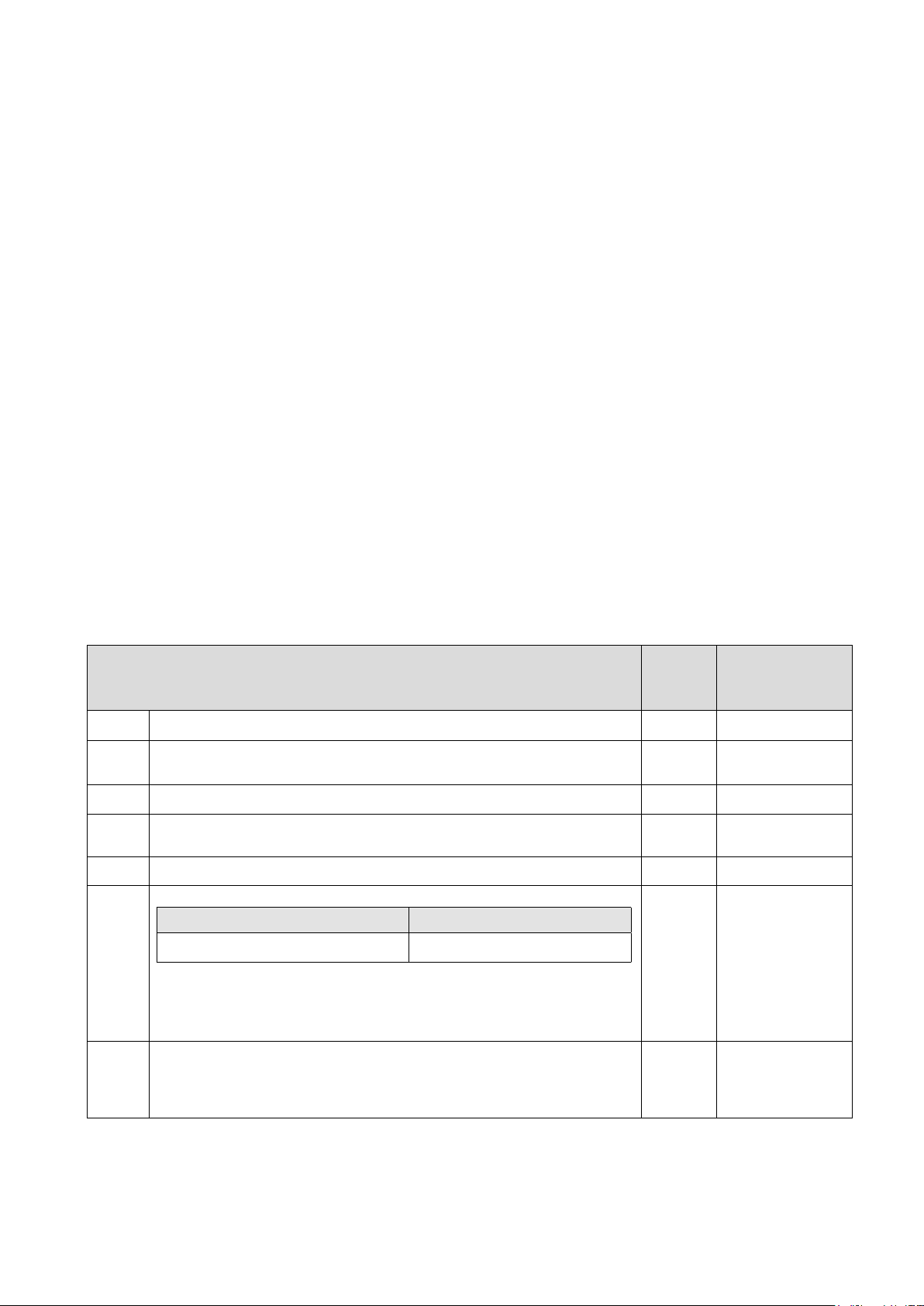
Basic pack / Extended pack Foil pack Wire pack with terminal
• Lower bearing assembly
• Halyard swivel
• Furling line
• Bearing halves
• Topguard
• Sail feeder
• Manual
In addition, the extended
pack includes halyard
leads, stanchion blocks and
pre-feeder.
• Luff extrusions
• Distance tubes
• Joining sleeves
• Connecting plates
• Wire with swaged eye
• Eye terminal with required
type of terminal (with or
without rigging screw)
Basic pack / Extended pack
The Furlex TD-system includes a basic pack with drum unit, torque tube, deck tting, halyard swivel, sail
feeder, bearing halves, top guard and furling line. In addition, the extended pack also includes halyard leads,
stanchion blocks and pre-feeder pack.
Foil pack, wire pack and wire terminal
The system also includes a foil pack with luff extrusions, distance tubes and connectors. A complete forestay
wire is also supplied with every Furlex and an eye terminal is swaged to its upper end. For the lower end, there
are three alternative terminals available:
1. Swaged terminal with eye (no adjustment).
2. Sta-lok terminal with eye (no adjustment).
3. Sta-lok terminal with rigging screw.
All three alternatives are used for 1x19 strand wire, but alternative 2 and 3 can also be used with rod, and
compact wire (Dyform). Rod forestays are always provided by the manufacturer of the rod.
For rod option supplementary manual 597-184-E ”Luff assembly for rod stay” is needed.
1.2 What’s included?
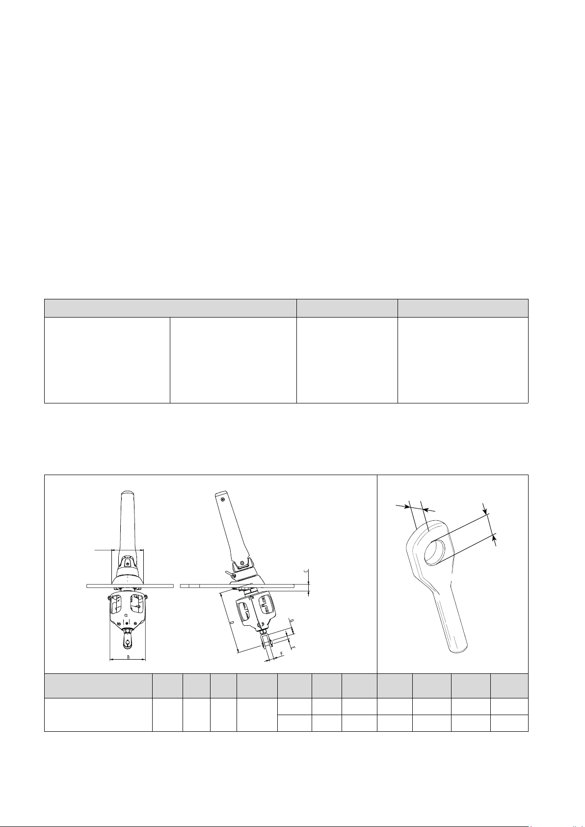
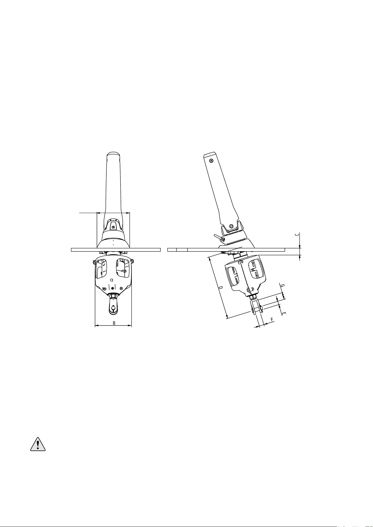
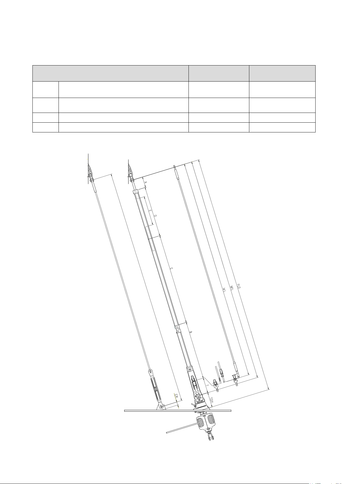
All dimensions are given in millimeters.
1.3 Main dimensions
Fig. 1.4.b
Fig. 1.4.a
Furlex
model A B C D E F G Wire
dim. Pin TED TET
404TD Ø12. Rod-30
182 210 40 375-540
Ø19 22 35 Ø12 Ø19 Ø19.5 16
404TD Ø14. Rod -40 Ø22 22 35 Ø14 Ø22 Ø23 17

5
10-15°
The information in this manual must be followed carefully to
avoid damage to the system and to aviod the risk of personal
injury. The warranty is only valid if the system is assembled and
operated according to this manual.
Please read the entire manual before assembly!
• Be very careful when you open the wire coil! It may spring
open and cause damage and/or personal injury.
• Never use a snap shackle to secure the standing rigging, not
even temporarily. When installing the system on a rigged
boat, always use a strong screw pin shackle or tie the
spinnaker halyard to a strong point on the boat before
removing the existing forestay.
• Incorrect halyard routing can result in ”halyard wrap” which
may cause severe damage to the forestay, and put the entire
rig at risk. The angle between the halyard and the forestay
must never be less than 10°.
•If using a winch for the furling line, rst check that there is
no obstruction which may interrupt the furling operation and
possibly cause damage.
• A common example is no furling line left on the line drum.
When furling the sail in heavy wind, the sail is packed
tighter and requires more furling line to be pulled than when
furling in light wind.
• Take care to ensure that all split pins are secured properly
after installation.
1.4 Safety precautions
Fig. 1.3.cFig. 1.3.b
Fig. 1.3.d
Fig. 1.3.a
Incorrect halyard routing can result in ”halyard wrap” which may cause severe
damage to the forestay, and put the entire rig at risk. The angle between the halyard
and the forestay must never be less than 10°!
May lead to

6
Fig. 1.5.c
1100
FLD
F
CB
Max sailspace FL -(F+E)
E
Furlex type 404TD
Head deduction F 630 (25”)
Tack deduction E
(Any additional pendant to the
tack must be added to E)
115 (4 1/2”)
Cutback CB 80 (3 5/32”)
Internal diameter of luff groove DLG Ø8 (5/16”)
Width of luff groove WLG 3.0 (1/8”)
Overall luff extrusion dimensions 52x38
(2”x1 1/2”)
Your sailmaker has all the necessary information through the Seldén Sailmakers Guide.
The Sailmakers Guide can be downloaded from www.seldenmast.com
Note that if you want to use an existing sail, it will need some modications.
• The luff length needs to be adjusted.
• A luff tape is required. The luff tape must be compatible with the Furlex luff extrusion geometry.
• Use webbing loops at the sail head and tack instead of grommets (cringles). The sail will then form tightly
round the luff extrusion when furling, and achieve a better shape when reefed.
1.5 Sail measurements
Fig. 1.5.a
Fig. 1.5.b
It is most important that the halyard swivel is located so that the halyard satises the
10–15° angle requirement. If the sail prevents the swivel from reaching the correct
position, the luff length needs to be adjusted.
IF THE SAIL IS TOO LONG: Shorten the sail, e.g. in conjunction with changing to a
luff tape compatible with Furlex.
IF THE SAIL IS TOO SHORT: Lengthen the sail by means of a HMPE or wire
pendant tted to the head of the sail. Attach the pendant directly to the sail to prevent
unintentional removal, loss or exchange.

7
2 Assembly preparations
2.1. Tools
2.2 Mast attachment
Before starting with the assembly, make sure you have the following tools available:
• Hack saw
•Torx bits and bit holder: T25; T30, T45
• Measuring tape
• Knife
• Hammer
• Pencil
If Sta-lok is to be tted you will also need:
• Small slotted screw driver
• Two adjustable spanners
• Pair of pliers
• Tape
• File
•Locking adhesive (included in the eye tting pack)
Always make sure that the forestay can articulate in all directions in the top. Toggles must be used in most
cases to ensure sufcient articulation.
Fig. 2.2.a Fig. 2.2.b Fig. 2.2.c
Tools needed for making the hole in deck:
• Template (1:1) (included in kit)
• Hole saw (see table) or jig saw
• Drill bit (see table)
Furlex model Hole saw ØDrill bit Ø
404TD 152 8,5
8
Attachment point at pin “E” must be xed in all directions.
A
The dimension C is nominal. In this area the thickness of the deck should not exceed 30 mm. If the deck is
thicker than 30 mm, it should be possible to reduce this with a cavity. This will allow the clearance for the top
forward drum edge. If the deck is of sandwich construction, ensure that water cannot enter the core material and
cause structural damage.
Furlex TD incorporates an adjustable fork terminal for ne adjustment of the under deck dimension ”D”.
For larger gaps: use a custom made stainless steel bar or rod stay. Short wire pendants are not recommended as
the forestay load may not be distributed evenly.
2.3 Hull attachment
The lower bearing assembly of the Furlex TD system is to be considered as an extension of the forestay tting
inside the hull. As it is locked horizontally at deck level, there is a toggle tted between the lower bearing
assembly and the forestay/luff section. This toggle, together with the universal joint function of the adapter
tube, will create the required articulation as per the guiding principle, item 3.1.
Check that the through-deck tting does not interfere pulpit, navigation lights or other deck ttings.
Check that the anchor well drains freely. Make sure that the forestay tting in the anchor well is designed
and constructed to take the full forestay load.
For dimensions - see page 4.
9
Fig. 2.4.b
Fig. 2.4.a
The by far best method is to stay the mast using
a forestay which extends though a smaller hole
in the deck (See g. 3.5.b). Below two different
methods to decide the intersection point are
listed. For both methods, it is assumed that the
deck is of uniform thickness.
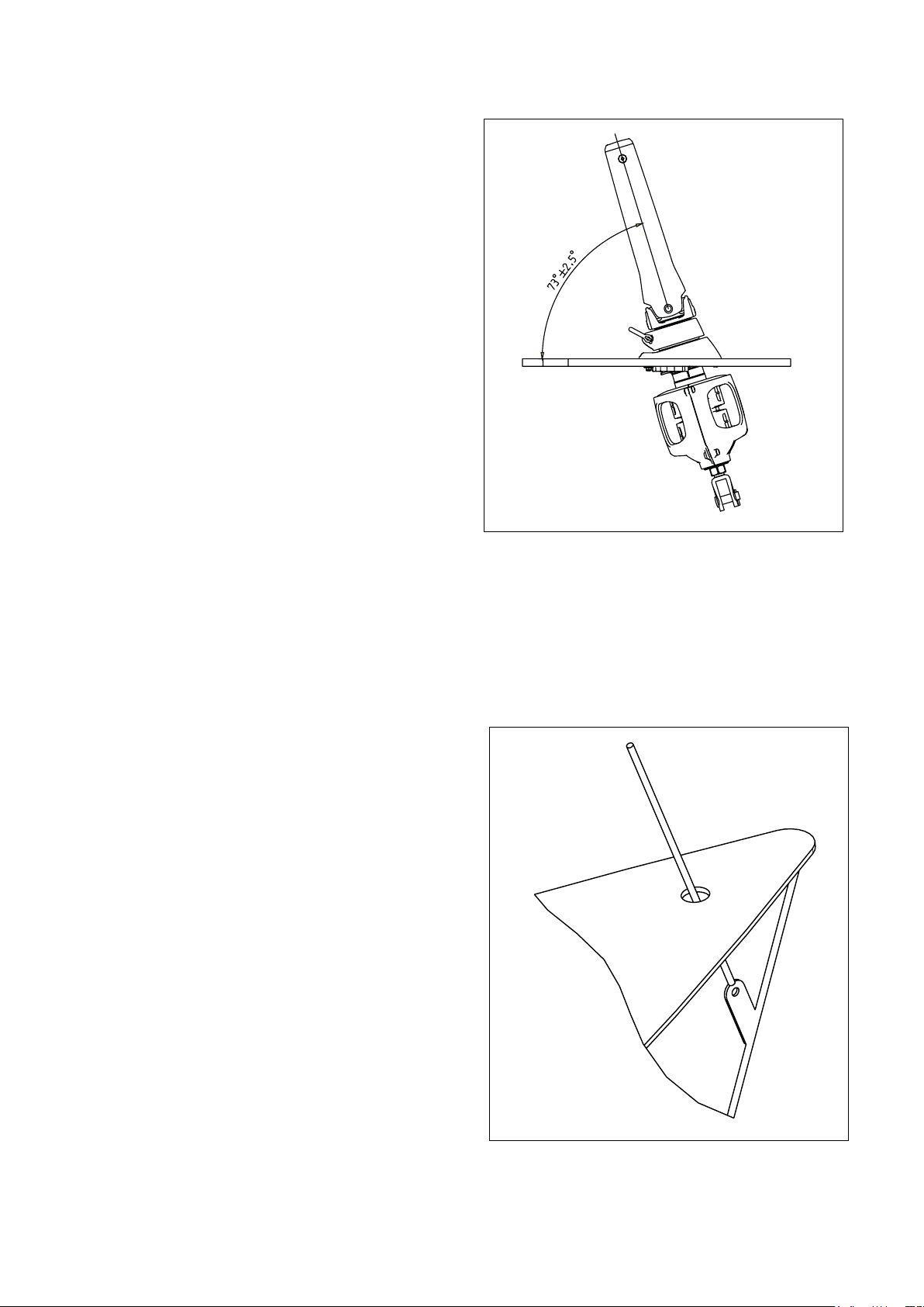
The bearing of the through-deck tting has a
spherical surface which compensates for smaller
angle discrepancies between forestay and
through-deck tting. However, it is important
to minimize the discrepancies to achieve maximum
furling performance. The angle between the
forestay and deck must be between 70,5° and 75,5°.
If the angle exceeds these limits, spacers must be
added between the through deck tting and the
deck, so that the conditions are fulllled.
How to decide the intersection point of the forestay on the deck.
2.4 Location of the through-deck hole

10
g. 2.4.c
2.4.1 Mast is not stepped 2.4.2 Mast is stepped using a forestay
attached to the final forestay chainplate
1. Establish the forestay angle. Use an accurate
drawing, which shows details of the area of the
deckwhere the Furlex will be attached (see g.
2.4.c).
2. Transfer this angle to a cardboard jig.
3. Press the jig against the underside of the deck
and move it longitudinally until the edge rep-
resenting the forestay line intersects the hole in
the forestay tting in the anchor well. Mark the
intersection point on the underside of the deck
and drill a 6.5 mm hole through the deck.
1. Make a jig which represents the forestay angle (FA)
above deck (See g. 2.4c)
2. Using this jig, mark the angle CSA between the
forestay tting in the anchor well and the forestay
intersection point
3. If these angles are equal, the existing forestay t-
ting is correctly located. If the angles are not equal
the forestay angle FA must be used also below
deck to decide the intersection point. Press the jig
against the underside of the deck and move it lon-
gitudinally until the edge representing the forestay
line intersects the hole in the forestay tting in the
anchor well. Mark the intersection point in the for-
and aft direction accurately on the underside of the
deck.
9. Remove the forestay. The recommended prodedure
is to rstly slacken the backstay. Pull the mast-
head forward using the genoa halyard. Secure the
halyard using a “D”- shackle or tie to a strong deck
tting. For safety reasons do not use the halyard
snap shackle. NOTE. If the forestay is to be used
to decide the forestay length FLD (se page 13), the
setting of any rigging screw must not be changed
10. Measure the distance CH (see page 13) of the
chainplate and enter the measurement in the table
at page 11.
11. Remove the forestay tting from the deck.
12. Mark the intersection point on the underside of
the deck by drawing a line along the longitudinal
centreline of the boat and using earlier marking as
per item 3.
13. Drill a 6.5 mm hole at the intersection point.
For further fitting work see item 3.1
Always use a strong ”D” shackle or tie the halyard!
11
2.5 Calculating the length of the forestay wire.
(The following is valid for a yacht with the mast stepped.)
1. Slacken the backstay as much as possible, but make sure that any rigging screw is not unscrewed so far
that the threads are no longer visible ”on the inside”. The forestay setting should not be adjusted. If there is
insufcient adjustment in the backstay, and the forestay rigging screw must be adjusted to allow removal,
rst mark its thread with adhesive tape.
2. Pull the masthead forward using the genoa halyard. Secure the halyard using a ”D” shackle or tie it to a
strong deck tting. For safety reasons, do not use the halyard snap shackle. Secure the opposite end of the
halyard properly.
3. Go up the mast. Connect a free halyard to the forestay. Then detach the forestay and lower it using the free
halyard. Bring the stay down and place it on a at surface. If the forestay rigging screw was slackened,
adjust it back to the tape mark
4. Measure the forestay length (FL) with just enough tension to keep the forestay straight on the ground
Forestay length (FL) is the distance between the hole in the swaged top terminal and the hole in whatever
lower part that was attached directly to the hole in the chain plate. Enter the measurement into ”Table 2”
below, in the row marked FL
If a Sta-lok terminal (with or without rigging screw) is included, the wire is supplied over-length. The wire has
a swaged eye terminal on one end while the other end is open (= without terminal). If your Furlex is supplied
with a xed-length forestay, with a swaged eye on one end and a swaged stud in the other end, skip this part
and go directly to 2.6. The same apply for rod stays.
If a stud-terminated stay is to be manufactured by a local rigger it is important to note that WL in this case
equals the length of the nished stay, from eye to end of stud, see page 13. WL is calculated in table 1.
Before assembly, an over-length wire (for Sta-lok) must be marked and nally cut to the correct length to t
the boat’s actual forestay length. To nd out the correct measurement, follow the steps below. If the mast is not
stepped, you can jump directly to step 4 stepped, you can jump directly to step 4.
Table 2. Calculation of forestay wire length Your
forestay
Example
404TD 12mm
with rigging screw 50%
extended
FL Existing forestay length including rigging screw, no tension. 16070
CH Add the distance between the hole in the chainplate and deck level,
along the direction of the forestay.
40
FLD FLD=FL+CH 16110
TDH Fixed deduction deck level/forestay attachment: 200 mm.200
NFL New forestay length NFL=FLD-TDH 16110-200=15910
TDeduction for wire terminal 210
WL Cutting measurement.. WL=NFL-T
The new forestay wire is to be marked at this point (For forestays with
swaged stud, WL equals the length of the nished stay from the upper eye
terminal to end of stud. See g 2.6.1 page 13.
15910-210=15700
Without rigging screw: With rigging screw:
75mm 210mm

12
Note! If the calculation gives a top extrusion length (D) that is shorter than 700 mm, the
calculation must be reworked by exchanging one of the 2400 mm extrusions with the uncut
1700 mm top extrusion. By doing so the top extrusion will be cut from a 2400 mm length
and its length will then exceed 700 mm. If the calculation gives a top extrusion length (D)
that exceedes 1700 mm, the top extrusion must be cut from one of the 2400 mm extrusions.
In this case the 1700 mm extrusion will not be used.
2.6 Calculating the length of the luff extrusion
The Furlex luff extrusion consists of a number of shorter sections. Starting from the bottom there is a 560 mm
luff extrusion connected to the drum unit and extending up to the sail feeder. Then, from the sail feeder and up
there are a number of full length luff extrusions (L=2400 mm) and nally there is a 1700 mm top extrusion that
has to be cut to length to suite the actual forestay length.
To nd out the cutting length of the top extrusion (D) and the length of the top distance tube (E), start with the
length of the forestay wire (WL) that was calculated in table 2. Then follow the steps in table 3 below. On xed
length forestays (incl. rod stays), verify WL by measuring the stay length from centre of eye to end of stud
(wire) or end of rod head.
Table 2. Calculation of top luff extrusion length and top distance tube length Your
forestay
Example
(404TD 12mm)
With rigging screw 50%
extended
WL Length of the new forestay wire (as per Table 2). 15700
A+B 930
NNumber of full length extrusions to be used:
N = ( WL - (A+B) )/2400
(15700-930
/2400=6.15
N=6
CTotal length of the number of full length extrusions (2400 mm) to be used:
C = N x 2400
6 x 2400 =
14400
D* Length of top luff extrusion:
D = WL – (A+B) – C
15700-930-
14400=370
XFixed deduction:
300mm
300
E* Length of the top distance tube:
E=D-X
370-300=70
Wire
Without rigging screw: With rigging screw 50% extended:
Ø12: 1040mm
Ø14: 1085mm
Ø12: 930mm
Ø14: 980mm
Rod
Without rigging screw: With rigging screw 50% extended:
-30: 1060mm
-40: 1080mm
-30: 965mm
-40: 970mm
13
Fig. 2.6.1
FL = existing forestay length
*If, as in our example, D becomes less than 700 mm it is necessary to recalculate as below and cut one of the full
length luff extrusions according to Dnew and one of the full length distance tubes according to Enew. Note that
the original top luff extrusion and the original top distance tube will now be used as intermediate extrusions.
Tabell 2B: Recalculation if D<400 mm Your forestay Example
Nnew Reduce the number of full length extrusions by one.
Nnew = N-1
N=5
Cnew Cnew = Nny x 2400 + 1700 5 x 2400 + 1700 =13700
Dnew Dnew = D + 700 370+700=1070
Enew Enew = E + 700 70+700=770
14
1. Using the 6.5 mm hole at the intersection point (see 3.5.3) as it centre, cut a 50 mm hole in the deck
2. Step the mast and use a genoa halyard (the one intended for the
Furlex) as forestay. Lead the halyard through the hole in the deck
and attach it to the hole in the forestay fitting Attach the halyard with
a D-shackle fitted to the halyard with a knot. If the halyard is fitted
with a snap shackle this should not be used for safety reasons.
3. Mark the position of the halyard on the edge of the
50 mm hole longitudinally as well as laterally.
4. Take the tension off the genoa halyard, using another halyard. Disconnect the rst genoa halyard.
5. Fit a sheet of wood, plywood or similar, using 3 screws as
per fig. 4.1.c. underneath the deck. Locate the holes close to
the hole edge to provide clearance for the saw/hole saw.
Note: To make the markings more precise, the 50 mm hole
should be filled with a piece of wood and fixed with
“quick curing “ filler.
6. Put the enclosed hole jig on top of the hole: Check that the jig
reference lines coincide with the deck markings.
Secure the jig with adhesive tape.
7. Cut the large hole using a hole saw or jigsaw. Do not make the hole too big. File if required.
Also drill the holes the tting screws (see page 7).
3 Assembly of the Furlex system
3.1 Making deck hole and fitting of through-deck fitting
The best way to decide the location of the through-deck fitting is to step the mast with a forestay,
which passes through a smaller hole in the deck. If using this procedure follow the instruction starting
at item 1. If making the hole for the through deck fitting is the first step, start at item 5.
NOTE! Always use a strong ”D”-shackle or tie the halyard!
15
E
D
BA
A
A
BX
8. Fit the through deck tting. The markings (A), fore and aft of the tting,
will help to center the tting in the longitudinal direction. The deck tting
has a compartment for sealing compound which can be used if required.
Check that the through deck tting rests against the aft edge of the hole when
the the screws are tightened.
If the deck thickness admits, an additional screw can be tted as per B.
If the deck is thin it can be necessary to increase its thickness locally for
the screws to sit rmly.
C
Fig. 5.1.b
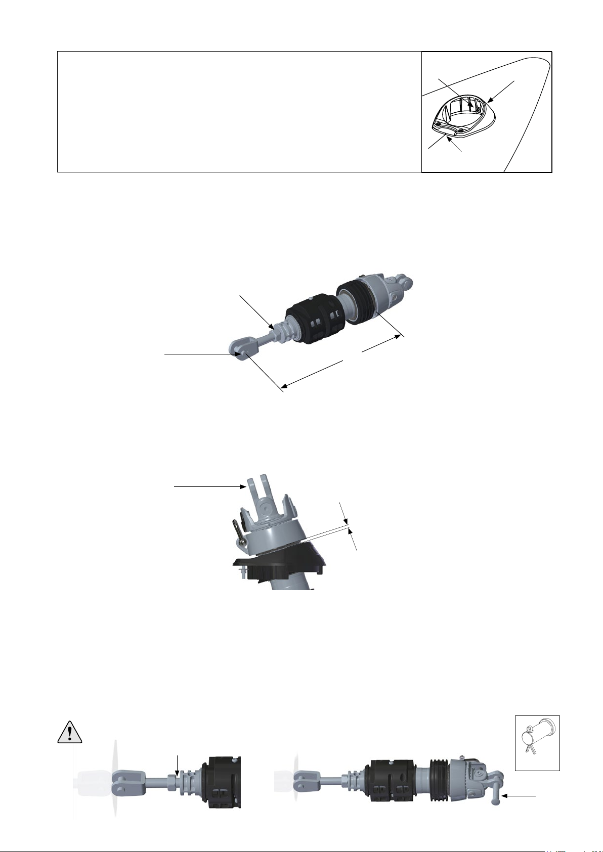
3.2 Fitting of the lower bearing assembly to the boat.
1. Measure the distance between the upper edge of the through deck collar and down to the hole of the chain
plate in the bow. Unscrew the fork terminal so that measurement (X) corresponds to this measurement +
~10mm. Unscrew and back off the nut (A) so that there is ~15mm between the nut and the face of the shaft.
2. Remove the clevis pin (B) and lower the bearing assembly through the deck collar. Attach the fork to the
chain plate. Fit the clevis pin but do not secure it with the split pin yet. Adjust the length of the bearing assem-
bly by turning the toggle (C). Adjust until the lower edge of the tack ring is about 4-5 mm from the throughdeck
collar. Lift the tack shackle upwards and rotate the tack ring. Check that the tack ring does not touch the
through deck collar at any point. The tack ring will tilt a little when under load which is normal.
3. Remove the clevis pin and lift up the lower bearing assembly. For electric systems this concludes the adjust-
ment, do not tighten the nut (A) . For manual systems continue as follows: Unscrew the fork terminal at least 5
turns, Note! count the turns. Apply a bead of locking adhesive to the thread (D) and screw the terminal back to
its original position (counting the turns). Tighten the locking nut firmly while clamping the toggle in a vise if
possible, or locking it with a screw driver or similar (E). This is a permanent setting of the length of the lower
bearing assembly, ensure the nut is tight.
Lower the bearing assembly through the deck fitting again. Fit the clevis pin and the split pin connecting the
fork to the chain plate. Lift the tack shackle upwards and rotate the tack ring ensuring the gap to the through
deck collar is still satisfactory.
Never adjust the swivel length with the forestay attached.
4-5 mm

16
A
B
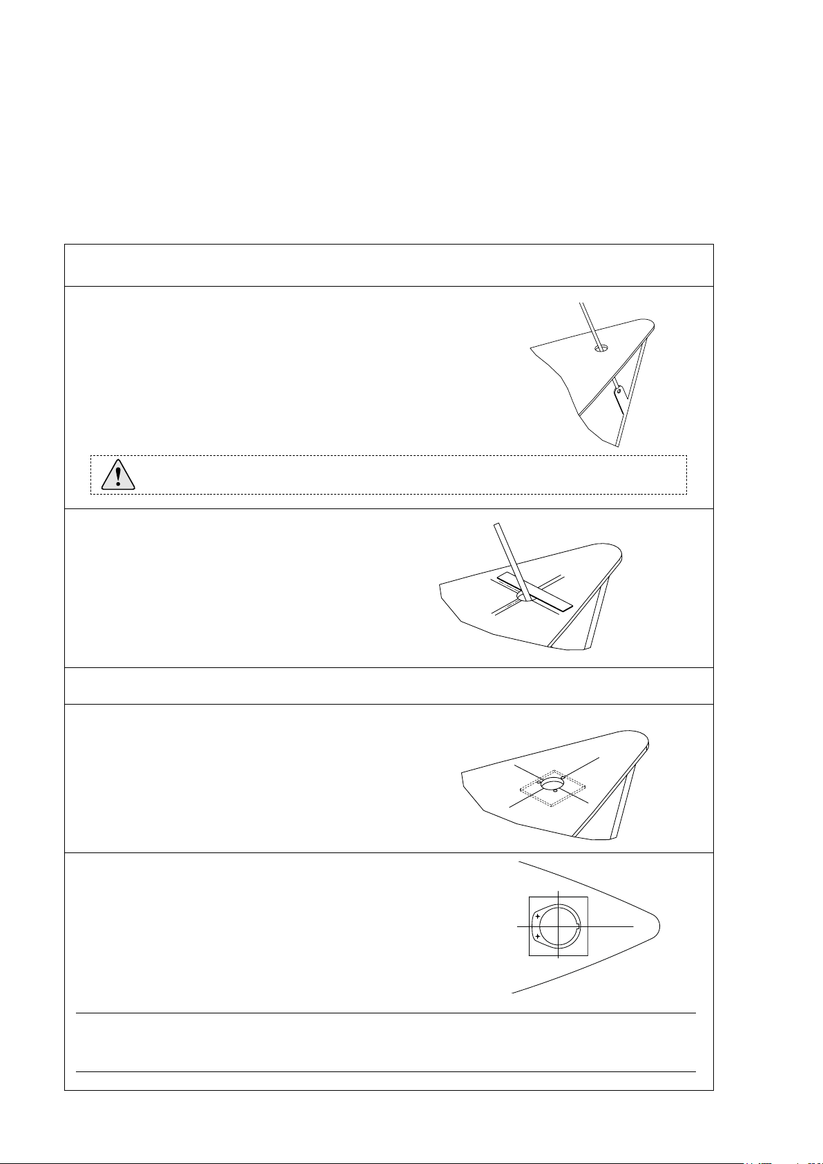
3.3 Fitting the furling line
Feed the furling line through the line guide cover half with the screws. Feed the rope through the two
”channels” in the drum. Fit the rst screw through the rope approximately 25 mm from the rope end. Then
tighten up the rope and push it into the jaw-slot before tting the second screw. Do not overtighten the screws!
If the sail’s ultraviolet (UV) protection is tted on the starboard side, the furling line shall exit on the port side
of the line drum and if the UV protection is tted on the port side the line shall exit on the starboard side.
3.4 Fitting the brims and
the line cover
1. Fit the four brims.
2. Fit the line-cover halves. Tighten the upper screws (B).
Do not over-tighten.
Tighten the lower screws (A) moderately. Fine adjustment of
the cover will be made after feeding the line on to the drum.
3. Feed approximately 30 turns of furling line on to the drum by turning the toggle clockwise if the line shall
exit on portside of the drum, anti-clockwise if it shall exit to starboard. Fine tuning of the drum is described in
chapter 5.3.
17
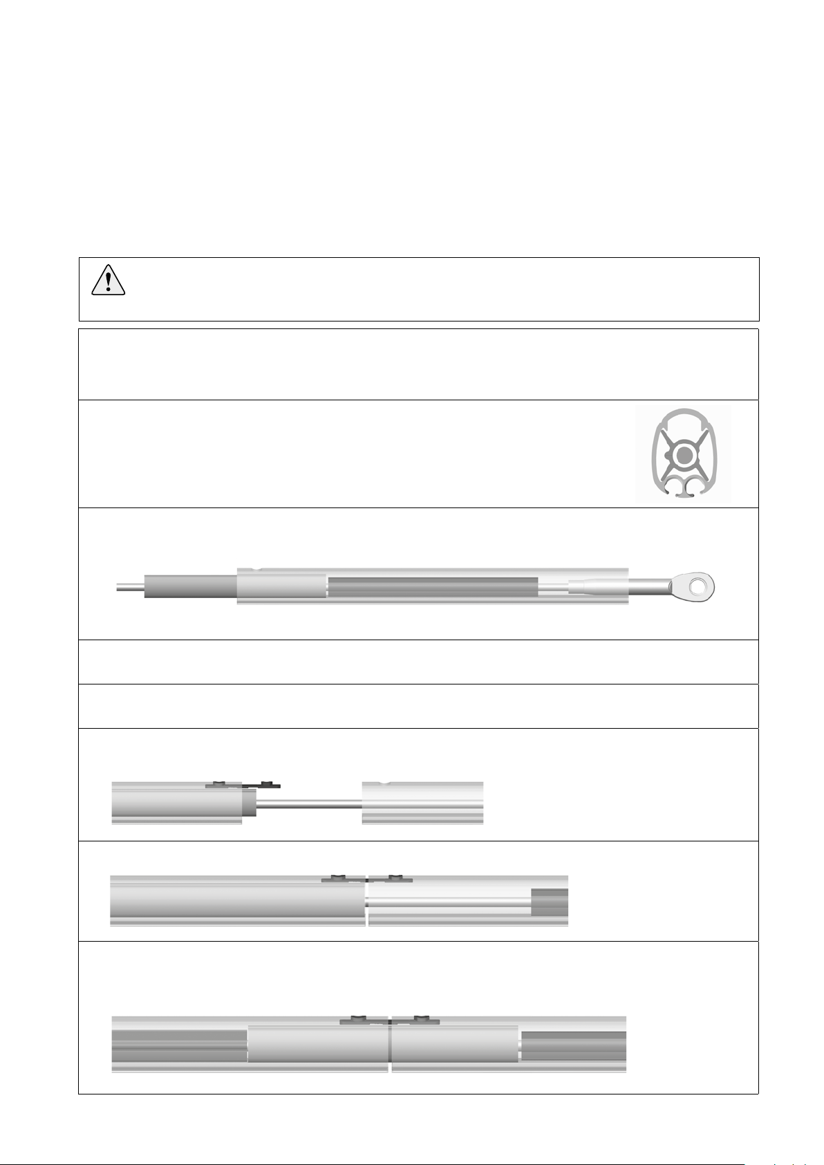
1. Stretch out the wire on a at, clean surface. On stays with swaged lower terminal, be careful not to
damage the terminal thread. The thread can be protected with tape or similar.
2. Start by feeding the top luff extrusion and the top distance tube onto the forestay wire.
The distance tubes are welded shut but are easily opened by hand. Note the correct
orientation of the distance tube - hinge to be sideways.
3. Add a short joining sleeve (300mm) and use it to push the distance tube up into the top luff extrusion. The
distance tube should be pushed in approximately half the length of a joining sleeve.
4. On Sta-lok terminated systems, the halyard swivel and the top guard can be tted at this point, see
below. On stud terminated systems, the top guard must be tted after the sail feeder has been mounted.
5. Add another luff extrusion and another distance tube. Make sure the distance tube is oriented correctly.
Also add another short joining sleeve.
6. Fit a short connecting plate into the second luff extrusion as shown. Push the rst joining sleeve down
into the second luff extrusion to lock the connector.
7. Connect the two luff extrusions.
8. Push the rst joining sleeve back up into the rst luff extrusion to lock the join. Use the second joining
sleeve to push on the second distance tube. The second distance tube should be pushed in approximately
half the length of a joining sleeve. This will ensure correct location of the rst joining sleeve.
4 Assembly
4.1 Assembly of the luff section
Luff assembly should be carried out on a clean, at surface. Make sure there is enough space for the entire
forestay length to be stretched out.
Note that the luff extrusions are tted onto the forestay, whereas on previous models the wire was tted as a
last step. Also note that the luff is assembled from top down as opposed to older Furlex systems. (Systems
mounted on rod stay are assembled the opposite way. Please refere to separate instruction 597-184-E).
Prior to the assembly of the luff extrusion, the top extrusion and the top distance tube shall be cut according
to table 3.
18
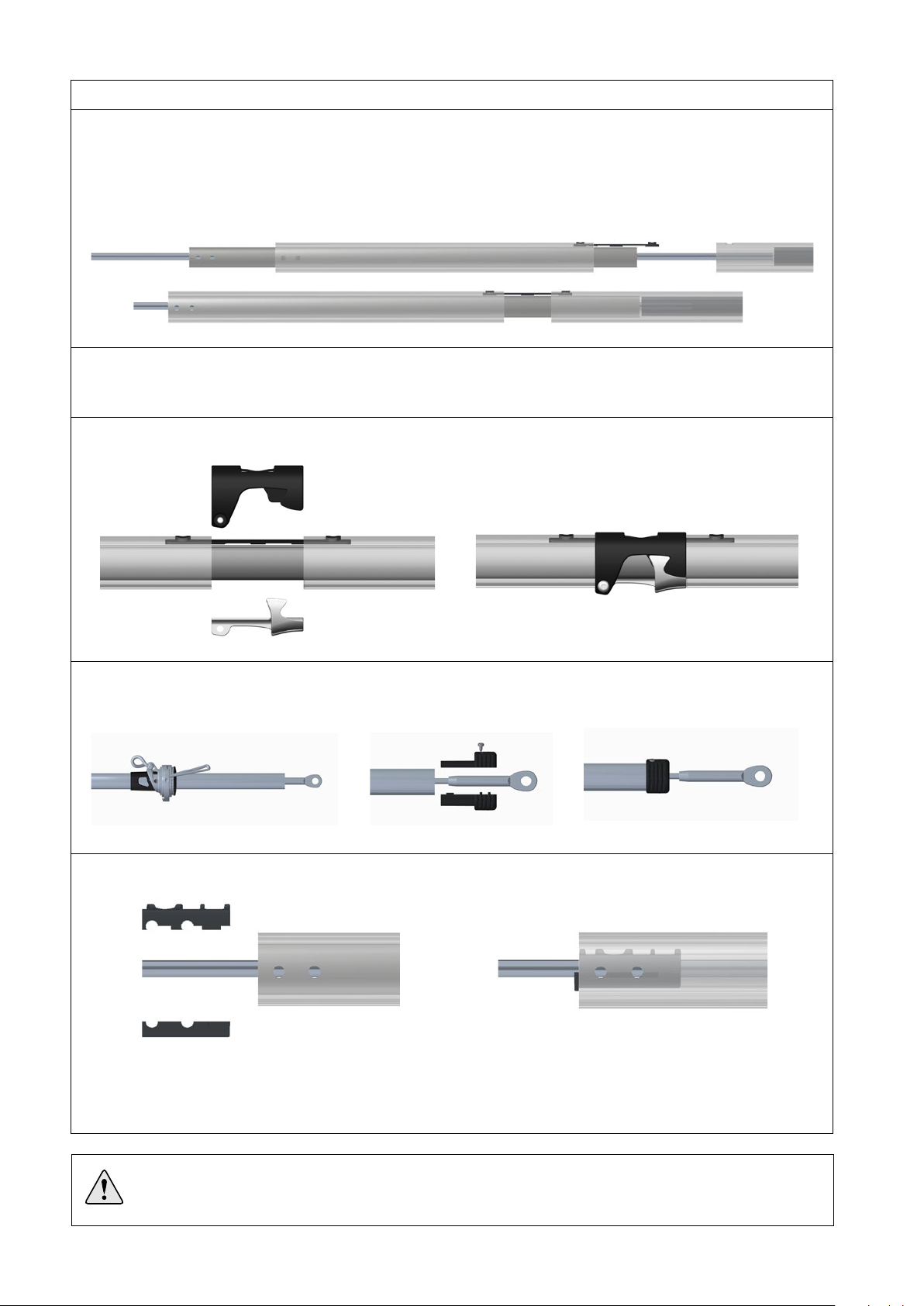
9. Repeat for the remaining 2400 mm luff extrusions. Use short joining sleeves only.
10. Fit the long joining sleeve (785mm) onto the wire with four-hole end oriented downwards. Then t
the short (560mm) luff extrusion, four-hole end oriented as shown. Fit the long connecting plate in the
560mm extrusion and push the long joining sleeve upwards to hold it in position. Connect to the upper
extrusion and push up the joining sleeve. Make sure the four holes in the lower end of extrusion are
aligned with the holes in the joining sleeve.
11. Fit the two grub screws in the connecting plate with locking adhesive. This will lock the distance tube
in position. Make sure that the holes in the lower part of extrusion/joining sleeve are aligned and tighten
the screws rmly.
12. Snap on the sail feeder connector and put the sail feeder in position. Secure with the screw and tighten
moderately.
13. Fit the halyard swivel from the top and slide it down until it stops on top of the sail feeder. Then t
the top guard and push it into the top luff extrusion until it stops. Secure it with the four pre-tted
screws. Tighten the screws until they bottom, but do not over-tighten.
14 Fit the bearing plug halves and push them up into the long joining sleeve.
This completes the luff assembly. Next step is to t the lower eye teminal to the stay. There are two
types of eye terminals; Stud/Eye terminal and Sta-lok eye terminal (with or without rigging screw).
Fig. 4.1.f
Fig. 4.1.g
Fig. 4.1.h
Fig. 4.1.i
NOTE! Compact-wire (Dyform®) requires a Sta-lok wedge made for this type of wire.
Seldén attaches a Compact wedge to the Compact wire pack.

19
2 mm
WL
15. Loosen the screws of the torque tube somewhat and feed the torque tube on to the luff section. Protect
the luff section and the torque tube with paper or plastic. Secure the torque tube with tape before rigging.
Mark the luff section 67 mm from the edge of the luff section to help aligning the screws with the holes
in the luff section at a later stage. Use a permanent marker pen.
4.2
Note! For systems with swaged stud terminal, skip this part and go directly to 4.3.
1. Before cutting the wire, measure the wire from the centre of the hole in the top swaged eye terminal.
Mark the measurement WL carefully on the wire using a marker pen. (The WL measurement was calculated
in ”Table 2”, (Chapter 2.5).
2. Put adhesive tape around the wire on both sides of the cutting mark to assist cutting. Carefully cut the
wire using a hacksaw.
3 . Unscrew the socket, wedge and former from the terminal part (or Furlex rigging screw).
Note! Remove locking tube from rigging screw and slide it over the lower luff extrusion. Secure it
temporaily with a piece of tape.
4. Thread the socket onto the wire.
5. Slide the wedge over the core (7 strands) of the wire . The core of the wire should protrude approx.
2 mm from the wedge.
15.
4.2 Fitting the Sta-lok eye terminal (with or without rigging screw).
Former
Terminal part (or rigging screw)
Wedge Socket
Fig. 4.2.a
Fig. 4.2.b
Fig. 4.2.c
Fig. 4.2.d
Fig. 4.1.j
67

20
6. Space the outer strands of the wire evenly around the
wedge and bring down the socket so that the strands are
held in place. Hold an adjustable spanner between the
700 mm extrusion and the socket.
Tapping the core of the wire, locate it firmly in the socket.
Check that the core of the wire protrudes approx. 2 mm
from the wedge. See fig. 3.2.d
7.Bend the outer strands inwards a little using a pair of pliers,
or tap the strands with a small hammer. In the latter case,
rest the socket’s thread on a soft surface (wood or similar) to
prevent damage.
8. Insert the former into the threaded hole of the terminal part. Lubricate the socket´s thread with a long
bead of locking adhesive. Screw the terminal part onto the socket and tighten carefully, forcing the wire
further into the terminal.
9.Unscrew and check that the outer strands are
evenly distributed around the wedge. If some
strands are crossed, correct their positions.
10. If assembly is unsuccessful and needs to be repeated, refer to the relevant sections of Chapter
7.4, ”Dismantling the Furlex”.
11. Apply another 2 or 3 drops of the locking adhesive
to the thread and screw the terminal together,
tightening it firmly. The terminal is now
permanently locked.
12. Fit the stainless locking tube back onto the rigging screw, if applicable.
Check that the length of the luff section corresponds to
the NFL measurement, table 2 page 11.
If it does, the luff section is now ready to be rigged.
NOTE! Check that no strands slip into the slot of the wedge
NOTE! Check that no strand has slipped into the slot of the wedge!
Table of contents
Other Selden Marine Equipment manuals

Selden
Selden Furlex 204S Guide

Selden
Selden Furlex 204TD User manual

Selden
Selden Furlex 100 S User manual

Selden
Selden Furlex 404S Guide

Selden
Selden Furlex Electric 200E User manual

Selden
Selden Furlex 200 S User manual

Selden
Selden Furlex 200 TD User manual

Selden
Selden Furlex 200 S User manual

Selden
Selden Furlex 104S Guide

Selden
Selden Furlex 400 S Supplement


