Selden Furlex 100 S User manual

Manual
Furlex
100 S
595-102-E
2011-04-15
100 S
2
To derive the maximum benefit and enjoyment from your Furlex system, we recommend that you
study this manual carefully.
The manual is divided into two sections, one dealing with ASSEMBLY and one with
OPERATION.
Each section contains references to the other. It is very important to read and note these cross
references.
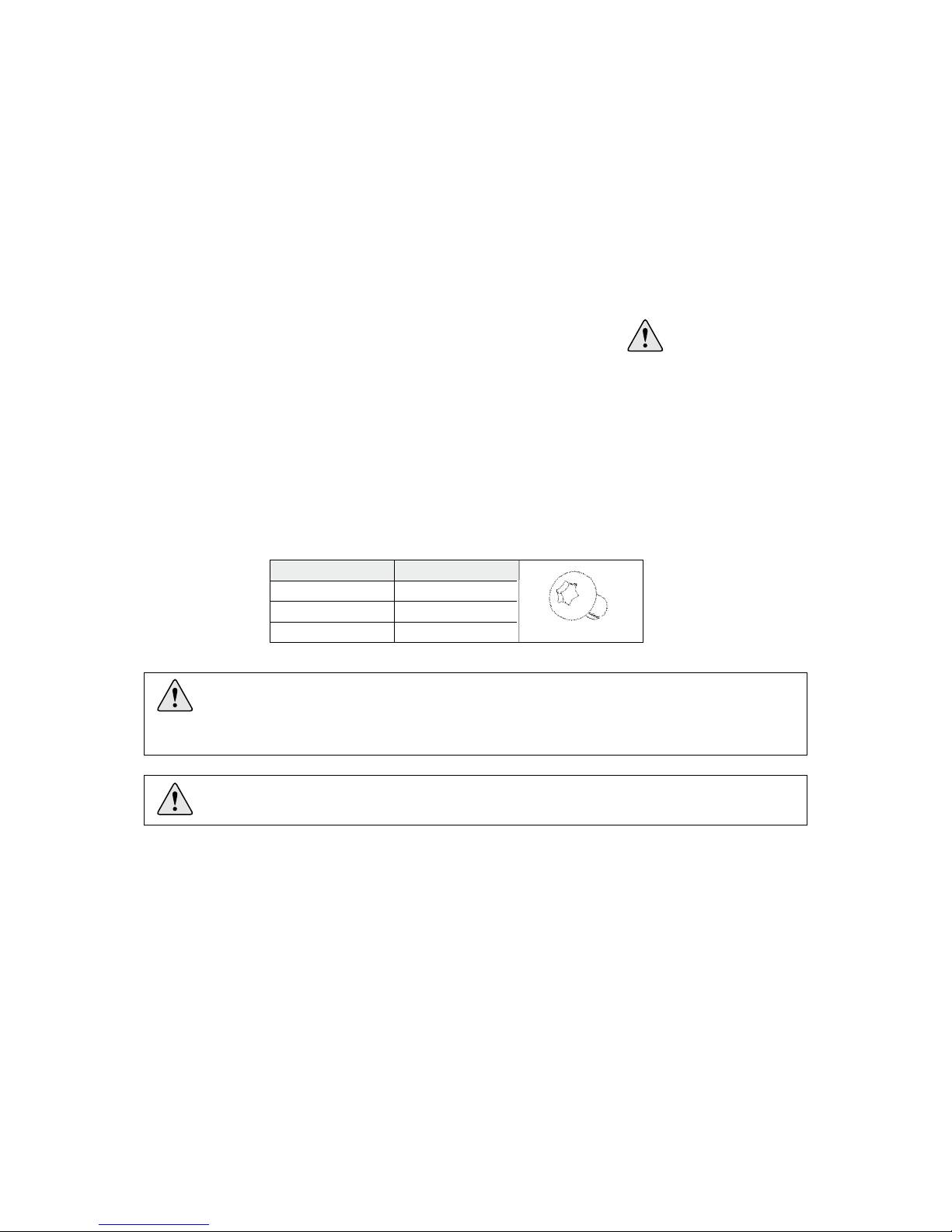
All safety-related information is indicated by the following symbol:
The manual covers one Furlex size, 100 S.
The model designation can be found on the line drum top.
Furlex is specified and manufactured using Metric dimensions. To assist owners unfamiliar with
this system, the approximate equivalent Imperial dimensions are given in brackets.
The screws used for the halyard swivel and lower bearing assembly have a Torx socket.
The Torx type socket has an excellent grip but is not yet in common use. The necessary torx bits
are included with the Furlex. The Torx socket sizes are:
This information must be followed to avoid damage to the system and the risk of
personal injury. The 5-year guarantee on the Furlex system is only valid if the system
is assembled and operated correctly according to the manual.
1 Introduction
PLEASE read the entire manual prior to assembly!
Seldén Mast AB guarantees the Furlex system for 5 years. The guarantee covers faults arising from
defective design, materials or workmanship.
The guarantee is only valid if the Furlex system is assembled, operated and maintained in accordance
with this manual and is not subjected to loads in excess of those indicated in the brochure and
instructions.
If the system is repaired by anyone other than Seldén Mast AB or one of our authorized dealers, the
guarantee ceases to be valid.
Seldén Mast AB reserves the right to alter the content and design without prior warning.
Torx SocketScrew Size
M5 T 25
M6 T 30
M8 T 40 Fig. 1.1.a
1.1 The manual

3
1 Introduction
1.1 The manual 2
1.2 Product information 4
ASSEMBLY
2 Checklist
2.1 Furlex box 6
2.2 Foil pack 8
2.3 Tools 8
3 Assembly preparations
3.1 Forestay attachment - guiding principle 9
3.2 Mast attachment 9
3.3 Deck attachment 9
3.3.1 Dimension of lower bearing assembly 10
3.3.2 Dimension of top eye terminal 10
3.3.3 Table of measurements for toggles 11
3.4 Assembly below deck 12
3.5 Calculating the length of the forestay wire 13
3.5.1 Table 1:
Calculation of forestay wire length 13
3.6 Calculating the length of the luff extrusion 14
3.6.1 Table 2: Calculation of luff extrusion length 14
4 Assembly of the Furlex-system
4.1 Assembly of the luff section 16
4.2 Fitting the wire terminal 17
4.3 Fitting the line drum and line guide 20
5 Halyard routing
5.1 Halyard leads 22
5.2 Halyard sheave box 23
5.2.1 Sheave boxes 23
5.3 Spinnaker halyard 23
5.4 Fitting the halyard lead 23
6 Furling line arrangement
6.1 Functional description 25
6.2 Winding the line onto the line drum 25
6.3 Routing of the furling line 26
6.4 Fitting the stanchion blocks 27
7 The Sail
7.1 Adapting the sail to the Furlex system 28
7.1.1 Table of sail measurements 29
7.2 Sail shape 29
7.3 Determining the length of the pendant 30
OPERATION 31
10 Halyard routing
10.1 Summary 32
10.2 Halyard sheave box 33
10.3 Spinnaker halyard 33
11 Sailing with Furlex
11.1 To hoist the sail 34
11.2 Unfurling the sail 35
11.3 Furling the sail 36
12 Reefing
12.1 Free turn 37
12.2 Reefing under sail 37
12.3 Setting a reefed sail from the furled position 38
12.4 Adjusting the sheeting position 38
13 Furlex for racing 39
14 Adjusting the forestay length
14.1 Furlex with rigging screw 40
14.1.1 Rigging Screw adjustment 40
14.2 Furlex without rigging screw 41
15 Maintaining your Furlex system
15.1 Lubricating the lower bearing assembly 42
15.2 Lubricating the halyard swivel 42
15.3 Cleaning the Furlex 43
15.4 Storage 43
16 Rigging
16.1 Fitting the Furlex on a stepped mast 44
16.2 Stepping the mast with Furlex fitted 45
17 Dismantling
17.1 Halyard swivel 46
17.2 Sail feeder 46
17.3 Line guide / Line drum 47
17.4 Forestay 48
17.5 Lower bearing assembly 49
17.6 Luff extrusion system 49
18 Troubleshooting 50
19 Checklist
19.1 Points to check before sailing 52
Contents
PagePage

4
When the original Furlex was introduced in 1983, it was not a pioneering project. The design included
features which improved on other manufacturers’ products to increase performance, function and
reliability. The first systems sold are still functioning well, providing ample proof of the design’s
effectiveness and long-term staying power. Furlex quickly became the market leader, a position it
still occupies today. Our success can also be put down to how we select a system for a specific yacht.
First we calculate the boat’s righting moment, which is a function of its displacement, ballast, beam
and draft. Then we use righting moment in combination with the rig type to calculate its power when
sailing, and the likely loads on the Furlex system.
Furlex is only sold through authorized local dealers who are able to cover all service requirements for
the customer, including assistance with assembly, the modification of sails or the production of new
sails.
This new Furlex model range incorporates improvements based on our extensive experience, and
represents the very latest development of the jib furling and reefing concept.
Furlex is supplied as a complete assembly kit containing all the components required.
The ball-bearing system of the halyard swivel features a load distribution facility, a unique
patented system which distributes loads over the entire ball race. This permits smoother furling
and considerably reduces bearing wear.
Furlex 100 S for Ø 6 mm forestay can be supplied with an optional external rigging screw.
The Furlex luff section has the same dimensions over its whole length. The entire luff is furled
in an even roll, right down to the tack of the sail. This is a requirement for satisfactory sail shape
when reefed.
The tack ring’s ”free turn” flattens out the sail, promoting an efficient shape when reefed.
Furlex is suited to both cruising and racing. The line drum and line guide are easy to remove if
you want to utilize the entire forestay length for racing.
The luff section has two luff grooves, allowing two jibs to be goose-winged when running down-
wind and facilitating fast sail changes for racing yachtsmen.
The prefeeder is always on hand to help when hoisting the sail.
The line guide fitting centres the line as it is wound onto the drum, and the flexible internal line
guard maintains light pressure on the line to ensure even distribution on the drum.
Furlex is manufactured by Seldén Mast, the world’s leading manufacturer of masts and rigging
systems.
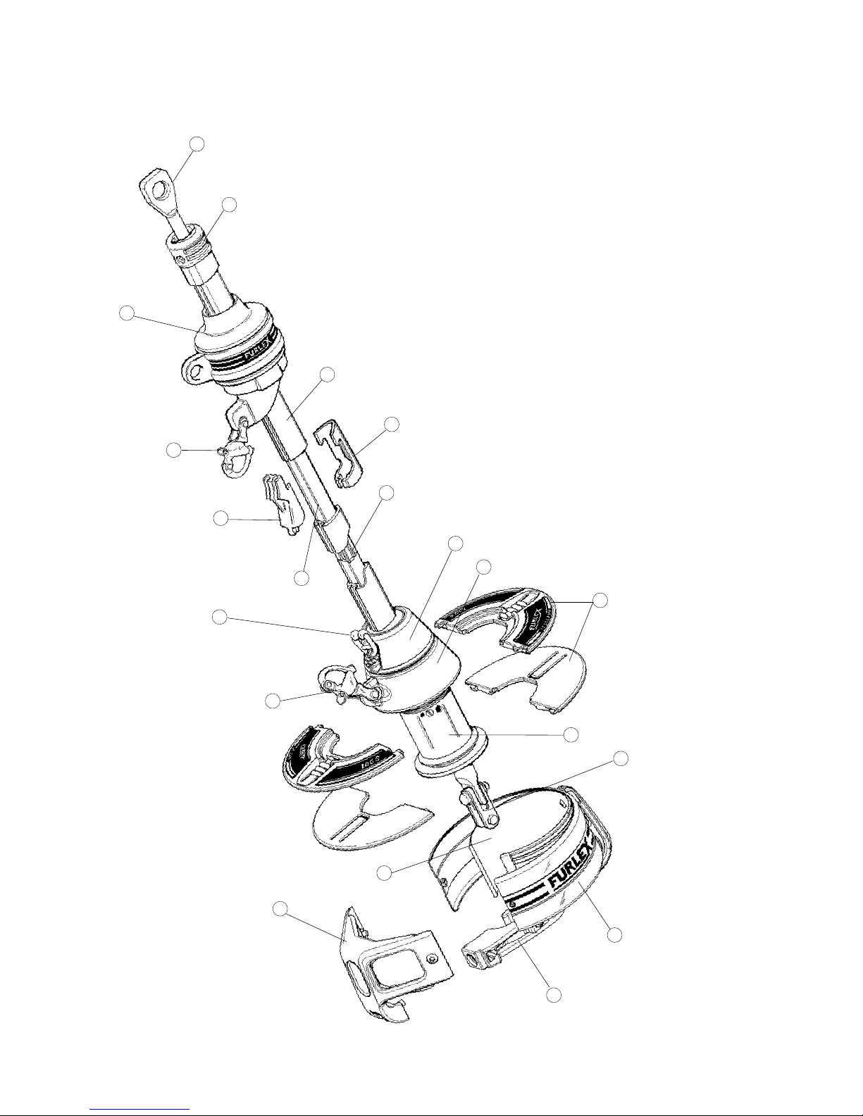
1.2 Product information
Follow the instructions carefully when fitting.
5
1. Forestay /eye terminal
2. Top guard
3. Halyard swivel
4. Snap shackle
5. Luff extrusion
6. Distance tube
7. Joining sleeve
8. Sail feeder
9. Sail feeder connector
10. Lower bearing assembly
11. Tack ring
12. Adapter
13. Fork / fork toggle
14. Line drum flange halves
15. Line guard housing
16. Line guard
17. Line guard bracket
18. Line guide fitting
19. Prefeeder
1
2
3
4
5
9
8
7
6
12
11
14
19
4
13
10
16
18
17
15

6
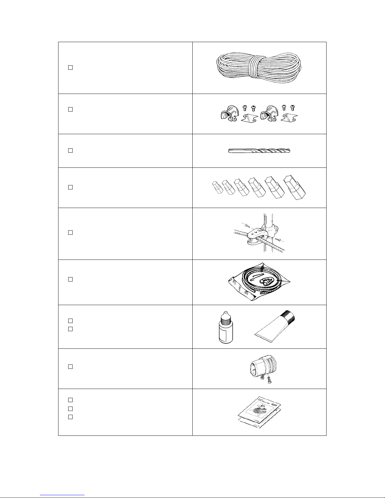
2 Checklist
2.1 Furlex box
Forestay wire
Halyard Swivel (with snap shackle)
Lower bearing assembly with snap shackle
4 Line drum flange halves
Line guard housing
Line guide fitting
ASSEMBLY
7
2 halyard leads 508-135 with insulator
sheets incl. 4 screws
Torx bit set (T15/20/25/30/40/45)
4 stanchion blocks
Top guard incl. 2 screws
Instructions
Spare parts list
Certificate of guarantee
Furling line
Drill bit Ø 5.3 mm (7/32”)
Prefeeder incl. shock cord and hook
Locking adhesive
Lubricating grease
8
Tools needed for assembly:
Screwdriver (standard tip)
Screwdriver for 1/4” bits
Hacksaw
2 adjustable spanners
Pair of pliers (“Polygrip”)
Adhesive tape
File
Marker pen (water-proof)
Torx bits (included in Furlex package)
Steel measuring tape (20 m) (60’7”)
Knife
For halyard leads:
Heavy-duty Philips screwdriver
Drill
Drill bit Ø 5.3 mm (7/32”) (included in package)
2.3 Tools
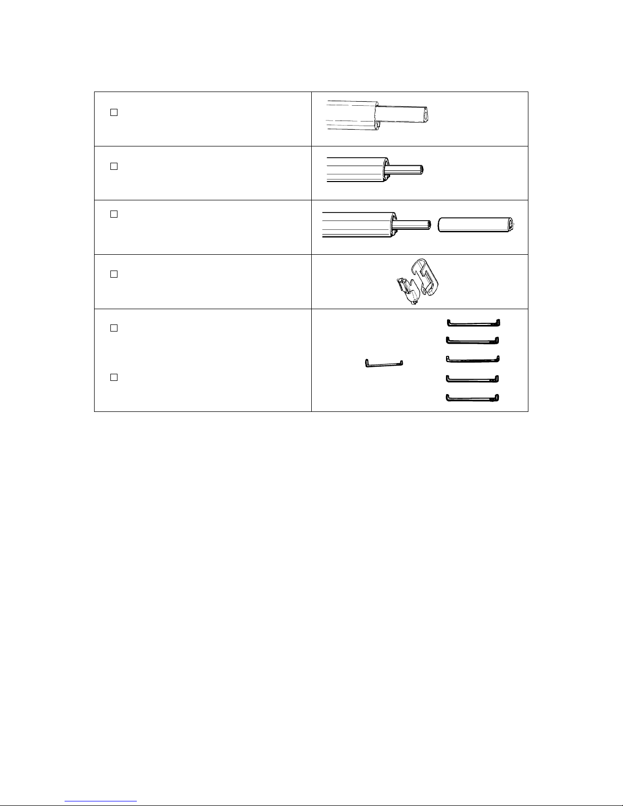
One x 1000 mm (39 3/8”) luff extrusion
with long joint sleeve.
One x 2000 mm (78 3/4”) luff extrusion
with distance tube.
2400 mm (94 1/2”) luff extrusions
with distance tube + joint sleeves.
(Number dependent on length ordered).
Sail feeder
(sail feeder + sailfeeder connector.)
One long connecting spring for each
2400 mm (94 1/2”) and 2000 mm (78 3/4”)
luff extrusion
One short connecting spring for the
1000 mm (39 3/8”) luff extrusion
2.2 Foil pack:
9
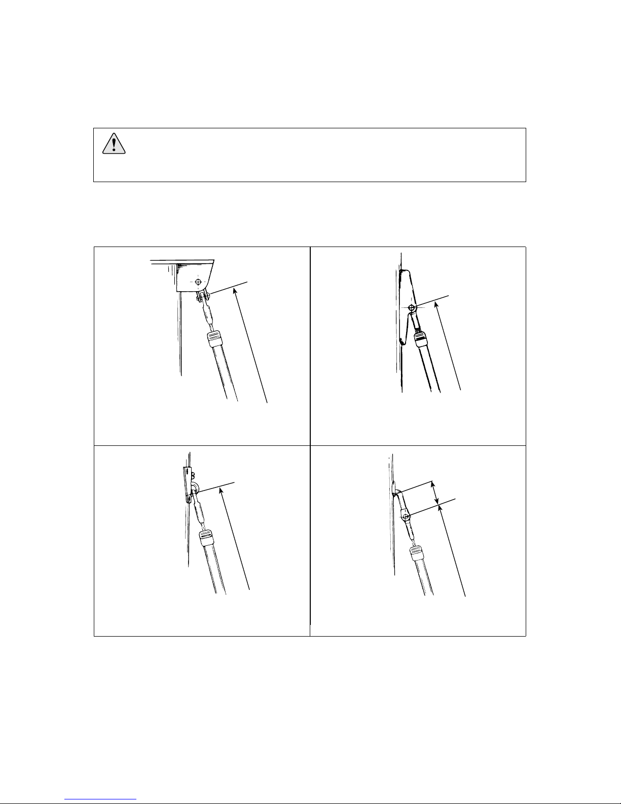
Forestay attachment on masthead rigs: Always
connect the stay with a toggle to give full
articulation.
Forestay attachment on fractional rigs, Seldén
triple combi box: 505-011; Ø4 & 5 mm wire:
Connect directly to fitting. 505-018; Ø6 mm
wire: Connect with an eye/fork toggle.
Forestay attachment Seldén’s fitting ”O - 22” /
”O - 35”: Connect directly to the fitting, which
provides full articulation.
Forestay attachment ”T-terminal” type:
Fit a T/fork toggle according to the table 3.3.3.
3 Assembly preparations
3.1 Forestay attachment - guiding principle
Some Seldén forestay attachment options are shown below, illustrating the rules and exceptions.
For H dimensions, see Table 3.3.3.
The lower end of the Furlex system is fitted with a fork toggle as standard. This can normally be
attached directly to the boat’s forestay fitting at the stemhead.
Check that the lower bearing assembly and line guide do not interfere with the pulpit, navigation
lights or other deck fittings.
Fig. 3.2.a Fig. 3.2.b
Fig. 3.2.c Fig. 3.2.d
The guiding principle is that the forestay connections should allow sufficient articulation
in all directions. In most cases a toggle should be fitted between the Furlex stay and
the forestay attachment.
FL
FL
FL
H FL
3.2 Mast attachment
3.3 Deck attachment

10
3.3.1 Dimensions of lower bearing assembly (mm) 3.3.2 Dimensions of top eye terminal
Wire dim. DD DH DW TED TET
Ø 4 (5/32”)
Ø 152 (6”)
~ 100 (4 ”)
80 (3 1/8”)
ø 8.2 (5/16”) 4 (5/32”)
Ø 5 (3/16”) ~ 100 (4 ”) Ø 10.2 (3/8”) 4.5 (5/32”)
Ø 6 (1/4”) ~ 120 (4 3/4 ”) Ø 12.2 (31/64”) 6 (1/4”)
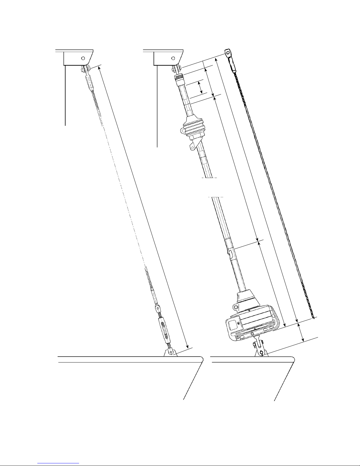
If the boat is fitted with a bow anchor, it may be
necessary to permanently raise the lower bearing
assembly to give the crew sufficient space for
anchor work. On Ø6 models, the adjuster shown
in table 14.1.1, or the extension link (table 3.3.3)
may be used for this purpose. Extension links for
Ø 4 & Ø 5 models are not stocked.
If the lower bearing assembly is raised by
means of an extension link, a Furlex toggle or
similar toggle with the same function should be
fitted between the link and the boat’s forestay
attachment.
Fig. 3.3.c
An extension link does not provide the necessary flexibility. It must always have a
toggle between it and the boat´s forestay attachment.
Fig. 3.3.a Fig. 3.3.b
Take care to ensure that the toggle
split pins are secured as per fig.
3.3.d after fitting.
Fig. 3.3.d
TED
TET
DD
DW
DH
20°

11
Toggle type
Forestay Dimensions
Ø 4 (5/32”) Ø 5 (3/16”) Ø 6 (1/4”)
Article no. 174-102 174-103 174-104
Length (H) 25 (1”) 35 (1 3/8”) 40 (1 1/2”)
Ø Eye (D1) 8 (5/16”) 10 (3/8”) 11 (7/16”)
Ø Clevis pin (D2) 8 (5/16”) 9,5 (3/8”) 11 (7/16”)
Fork width (W2) 8 (5/16”) 10 (3/8”) 12 (1/2”)
Article no. 517-056-02 517-054-02 517-046-02
Length (H) 25 (1”) 30 (1 3/16”) 40 (1 1/2”)
Ø Clevis pin (D1) 8 (5/16”) 10 (3/8”) 12 (1/2”)
Fork width (W1) 7,5 (9/32”) 10 (3/8”) 11 (7/16”)
Ø Clevis pin (D2) 8 (5/16”) 10 (3/8”) 10 (3/8”)
Fork width (W2) 8 (5/16”) 11 (7/16”) 11 (7/16”)
Article no. 174-127 174-128 174-122
Length (H) 60 (2 3/8”) 70 (2 3/4”) 80 (3 1/4”)
Ø Clevis pin (D2) 8 (5/16”) 9,5 (3/8”) 11 (7/16”)
Fork width (W2) 8 (5/16”) 10 (3/8”) 12 (1/2”)
Article no. - 517-065-01 517-066-01
Length (H) - 138 (5 7/16”) 152 (6”)
Ø Stemball (D1) - 26 (1 1/32”) 26 (1 1/32”)
Height (HB) - 8,5 (1/3”) 8 (5/16”)
Radius (R) - 10 (3/8”) 10 (3/8”)
Ø Clevis pin (D2) - 10 (3/8”) 10 (3/8”)
Fork width (W2) - 11 (7/16”) 11 (7/16”)
Article no. - - 517-063-01
Length (H) - - 90 (3 9/16”)
Ø Clevis pin (D1) - - 12 (1/2”)
Fork width (W1) - - 11 (7/16”)
Ø Eye (D2) - - 12 (1/2”)
Gauge (W2) - - 6 (1/4”)
Furlex-rigging screw, see chap. 14.
W2
HB
H
R
D1
D2
11
3.3.3 Table of measurements for toggles
(Toggles available from your Furlex dealer)
Eye / fork toggle
Fig. 3.3.e
Fig. 3.3.f
Fork / Fork toggle
Fig. 3.3.g
T / fork toggle
H
D2
W2
Fig. 3.3.h
H
D2
W2
D1
D2
W2
H
D1
W1
Stemball / Eye toggle
with Fork / fork toggle
Eye / fork Extension link
Fig. 3.3.i
D2
H
W2
D1
W1
Fig. 3.3.j

12
The lower bearing assembly can be fitted below deck inside an anchor well.
The advantage is that the sail’s luff length is maximized and the access around the forestay is improved.
The disadvantage is a more complicated route for the furling line, increasing furling resistance. The
diagrams below illustrate various methods of installation.
For the furling line to be wound evenly onto the line drum, the first turning point must be at least
250 mm (10”) away.
The tack should be located as close to deck level as possible.
Regardless of which option is chosen, the Furlex system must always be kept clear of the deck
well’s inside surfaces.
Avoid routing the line through an integral deck conduit, as this will increase the friction on the
furling line.
Use a large ball-bearing block to minimize friction losses.
The anchor well must be well drained.
To avoid damage to the Furlex system and the boat, the system must never be allowed
to come into contact with the edge of the deck or well when sailing.
Top edge of drum at deck level.
Large deck hole required for line drum.
Furling line led aft via turning block
and inset deck sheave box, then aft
along the deck.
Tack snap shackle at deck level.
Requires smaller hole in deck.
Furling line leads forward to an inset
deck sheave box, alternatively aft via a
block + deck sheave box.
Lower bearing assembly in the bottom
of the anchor well. Long webbing band
attached around the extrusion
May put too much strain on the furling
extrusion.
Fig. 3.4.a
Fig. 3.4.b
Fig. 3.4.c.
3.4 Assembly below deck

13
Deduction for lower wire terminal:
Ø 4 mm wire: – 45 mm (1 3/4”)
Ø 5 mm wire: – 55 mm (2 5/32”)
Ø 6 mm wire: – 70 mm (2 3/4”)
T
Existing forestay length (FL), including rigging screw (See fig. 3.5.a)FL
=
Furlex fitted above deck, but with the forestay fitting
in the anchor well.
Use the Furlex extension toggle. For a larger gap, use
a custom-made stainless steel bar or rod stay. For Ø 6
only, the Furlex rigging screw or extension link may
also be used.
Short wire pendants are not recommended as forestay
forces may not be distributed evenly, and wire will not
resist the torque which may be produced.
1. Determine the rake of the mast with the fore-/backstay tensioned.
2. Slacken the backstay as much as possible, but make sure that any rigging screw is not unscrewed
so far that the threads are no longer visible ”on the inside”. The forestay setting should not be
adjusted. If there is insufficient adjustment in the backstay, and the forestay must be adjusted to allow
removal, first mark its thread with adhesive tape.
3. Pull the masthead forward using the genoa halyard. Secure the halyard using a ”D” shackle or tie it
to a strong deck fitting. For safety reasons, do not use the halyard snap shackle.
Always use a strong ”D” shackle or tie the halyard!
4. Take down the forestay. If it was slackened, adjust the rigging screw back to the tape marks.
5. Measure the forestay length (FL) with just enough tension to keep it straight.
6. Enter the measurement in Calculation Table 1 below, under the heading ”Your forestay”, in the row
marked FL.
7. Calculate the new wire length WL in Table 1. Refer to the column marked ”example” to see how
this is done.
Your
forestay
Example
Ø5
Table1: Calculation of forestay wire length
3.5.1
H
WL
If a Furlex rigging screw (Ø 6 mm forestay only), links or extra toggles
are to be used, deduct this length (H) from FL.
Cutting measurement. The new forestay wire is to be marked
at this point.
--190
=13100
Fig. 3.4 d.
9.675
55
9.620
3.5 Calculating the length of the forestay wire

14
If the top extrusion is shorter than 400 mm (15 3/4”), the joint
will be too near the top. In this case replace the uppermost full-
length 2400 mm extrusion with the 2000 mm extrusion. In this
way the joint is moved 400mm (15 3/4”) down the stay. Adjust
the C and D measurements as follows:
Deduct 400 mm (15 3/4”) from the C measurement.
Add 400 mm (15 3/4”) to the D measurement.
-
1. Insert the length of the new forestay wire (WL) as calculated in table 1 into table 2, in the row
marked WL.
2. Calculate the number of full length extrusions and the length of the top extrusion.
Fixed deduction (A+B):
C+D=
3.6.1
WL
A+B
C+D
C
D
Max. number of 2400 mm (7’ 10 1/2”) extrusions which together are
shorter than C+D: [ ............ x 2400 = C ] C=
Length of top extrusion =
The top extrusion is normally cut from the 2000 mm extrusion.
Round the edges of the cut end using a file.
Ø 4 mm wire: E = D – 120 mm (4 3/4”)
Ø 5 mm wire: E = D – 120 mm (4 3/4”)
Ø 6 mm wire: E = D – 200 mm (7 7/8”)
Cut the distance tube for the top extrusion in accordance with
the following fixed deduction:
E
Deduction:
Length of distance tube E =
-
=
Table 2: Calculation of luff extrusion length
Length of new forestay wire (as per Table 1)
Your
extrusion
Example
Ø 5
-1395
=1395
–1395
(3 extrusions)
-
=2115
=
Ø 4 mm wire: – 1340 mm (4’ 4 3/4”)
Ø 5 mm wire: – 1340 mm (4’ 4 3/4”)
Ø 6 mm wire: – 1290 mm (4’ 2 3/4”)
9.620
1.340
8.280
7.200
1.080
120
960
3.6 Calculating the length of the luff extrusion
15 15
FL = Existing forestay length
Fig. 3.5.a
A
E
CB
D
WL T

16
Insert one end of a 144 mm (5 11/16”) spring in the upper hole of the
1000 mm extrusion, and slide the long joining sleeve up to hold it in
place. Remove the 200 mm (7 7/8”) joining sleeve from a 2400 mm (94 1/2 ”) extrusion.
This will be used later in the 2000 mm (78 3/4”) extrusion. Connect the 2400 mm extrusion and
the 1000 mm extrusion. Push the long joining sleeve up into the 2400 mm extrusion to secure the
connection spring. Continue pushing until the bottom of the sleeve is 50mm inside lower end of
the 1000 mm extrusion. A 50 mm (2”) gap is formed at this joint (as shown in fig. 4.1.c.), where
the sail feeder is to be fitted later.
Fit the short connecting spring (L=103 mm/4 1/8”) to the 1000 mm (39 3/8”) extrusion. The larger
hook must be on the free end. Push the long joining sleeve (L=1168 mm/46”) down, to hold the
spring in place and make space for the next spring.
Connect the remaining extrusions as detailed in table 3.6.1.
Fig. 4.1.a
Fig. 4.1.c
Fig. 4.1.d
1.
2.
4.
3.
Assembly should be carried out on a horizontal surface. Connect the luff extrusions one by one,
starting at the lower bearing assembly.
90 mm (3 9/16”)
20 mm (13/16”)
The extrusions are then fitted to the adapter of the lower bearing assembly. Hook the connecting
spring to the internal hole in the adapter. Then push the distance tube in the 2400 mm extrusion
down so that the joining sleeve bottoms in the adapter. The distance tube should be buried
approximately 100 mm (4”), about equal to half a length of a joining sleeve.
≈ 50 mm (≈2”)
≈ 100 mm (≈2”)
Fig. 4.1.b
4 Assembly of the Furlex System
4.1 Assembly of the luff section

17
Fit the halyard swivel over the top end of the extrusion, slide it down as far as the sail feeder gap
and secure it in this position with adhesive tape. Fit the top guard and secure it with the two pre-
fitted screws. Tighten the screws until they bottom, but do not over-tighten.
5
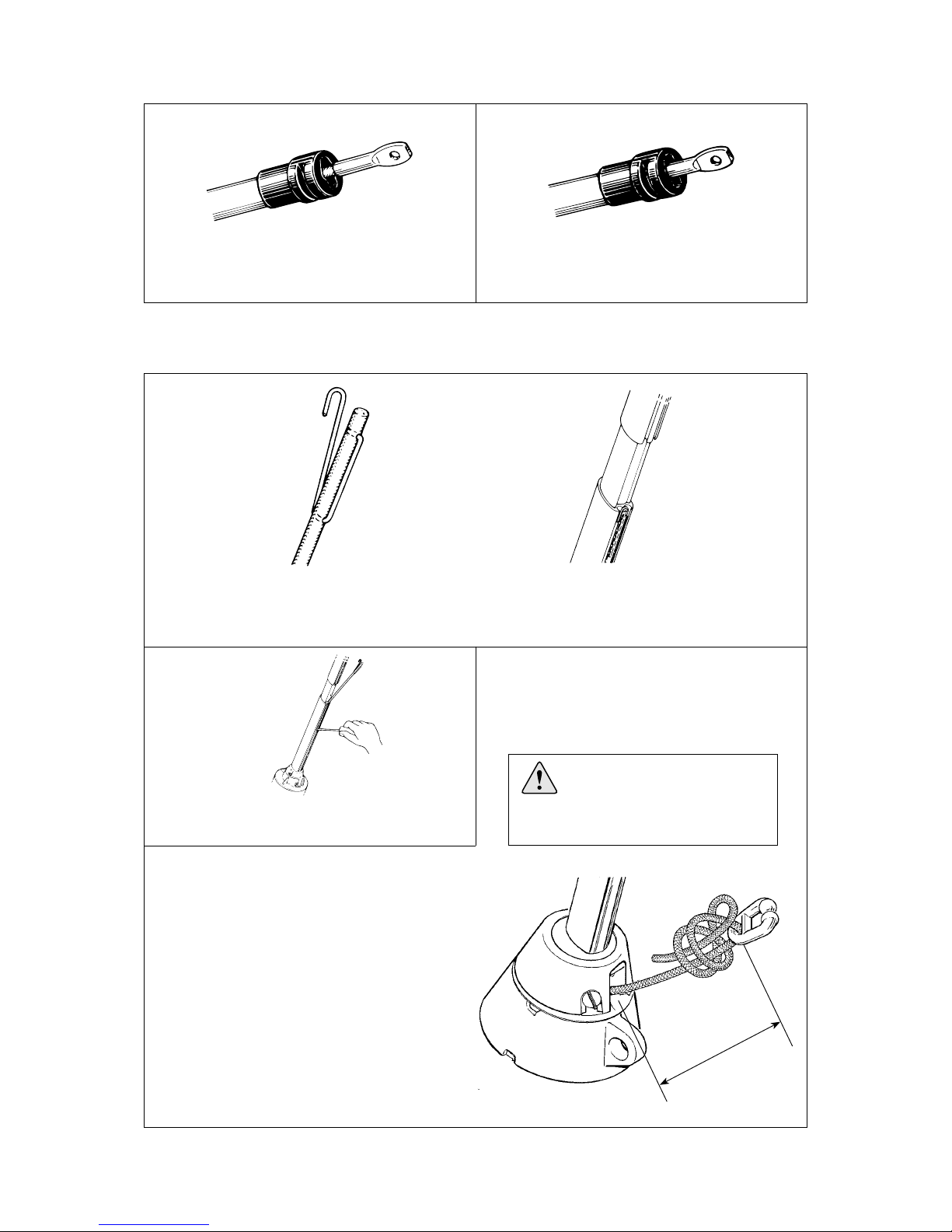
1. Stretch the Furlex wire out by hand on a flat surface.
Be careful when you open the wire coil as it may uncoil quickly.
Note! Be careful when you open the wire coil !
2. Measure the wire from the centre of the hole in the terminal end fitting. Mark the measurement WL
carefully on the wire using a marker pen. (The WL measurement was calculated in Table 1 (3.5.1)
3. The wire is annealed and tapered, making it easier to fit into the extrusion. Do not cut the wire yet.
5. Feed the wire through the luff extrusions from the top until the eye of the end fitting stops against
the top guard. If the wire catches inside the extrusion, turn it counter-clockwise until it passes the
obstruction.
6. Put adhesive tape around the wire on both sides of the cutting mark to assist cutting. Check that
the distance between the cutting mark and the terminal’s lower edge is approx. 30-50 mm
(13/16”- 2”).
7. Cut the wire. Round the end of the wire using a file.
4.
Unscrew the eye, wedge and former from the terminal part.
Fig. 4.2.a
Fig. 4.2.c
8.
Slide the wedge over the core (7 strands) of the wire .
Eye Former Wedge
Fig. 4.1.e
4.2 Fitting the wire terminal (or rigging screw)

18
9.
The core of the wire should protrude approx. 2 mm (3/32”) from the wedge.
Space the outer strands of the wire evenly around the wedge and push it into the socket so that the
strands are held in place. Tap the wire lightly so the outerstrands jam in the seat.
NOTE! Check that no strands slip into the slot of the wedge.
Fig. 4.2.d
10. Bend the outer strands inwards a little using a pair of pliers, or tap the strands with a small
hammer. In the latter case, rest the socket’s thread on a soft surface (wood or similar) to prevent
damage.
12.
Unscrew and check that the outer strands are evenly distributed around the wedge. If some strands
are crossed, correct their positions.
NOTE! Check that no strand has slipped into the slot of the wedge!
13. If assembly is unsuccessful and needs to be repeated, refer to the relevant sections of chap.
17, ”Dismantling”.
Fig. 4.2.f
11.
Insert the former into the threaded hole of the eye part (or rigging screw). Screw the terminal part
onto the socket and tighten carefully, forcing the wire further into the terminal.
Fig. 4.2.e
14.
Apply 2 or 3 drops of the locking adhesive to the thread and screw the terminal together, tightening
it firmly. The terminal is now permanently locked.
Fig. 4.2.g
2 mm
19
15:1 15:2
Furlex 100 S with Ø 4 or Ø 5 mm wire:
The swaged end fitting will protrude completely.
Furlex 100 S with Ø 6 mm wire:
About half of the swaged fitting will be exposed.
Fig. 4.2.h Fig. 4.2.i
17.
18.
19.
Fig. 4.2.l
16. Check the length FL of the stay acc. Table 1 (3.5.1) & fig. 3.5.a. Check that the setting is the
same as the H-measurement as in table 1.
The hook is connected to the rubber cord acc. to fig. 11.1. Feed the cord through the starboard sail
groove as shown in fig. 4.2.k and then through the slot in the lower bearing assembly.
Fix the hook in position.
Use a small screwdriver to pull the top of the
rubber cord down the luff groove.
Fig. 4.2.j Fig. 4.2.k
It is most important that the
prefeeder is correctly fitted,
or it will not function
correctly.
Tension the cord as hard as possible and tie the
pre-feeder to the cord as shown, 300 mm (12”)
from it’s exit sheave. Tighten the knot and cut
off excess cord.
CAUTION: If the cord is too loose the pre-
feeder may be thrown out by centrifugal
force when the system rotates.
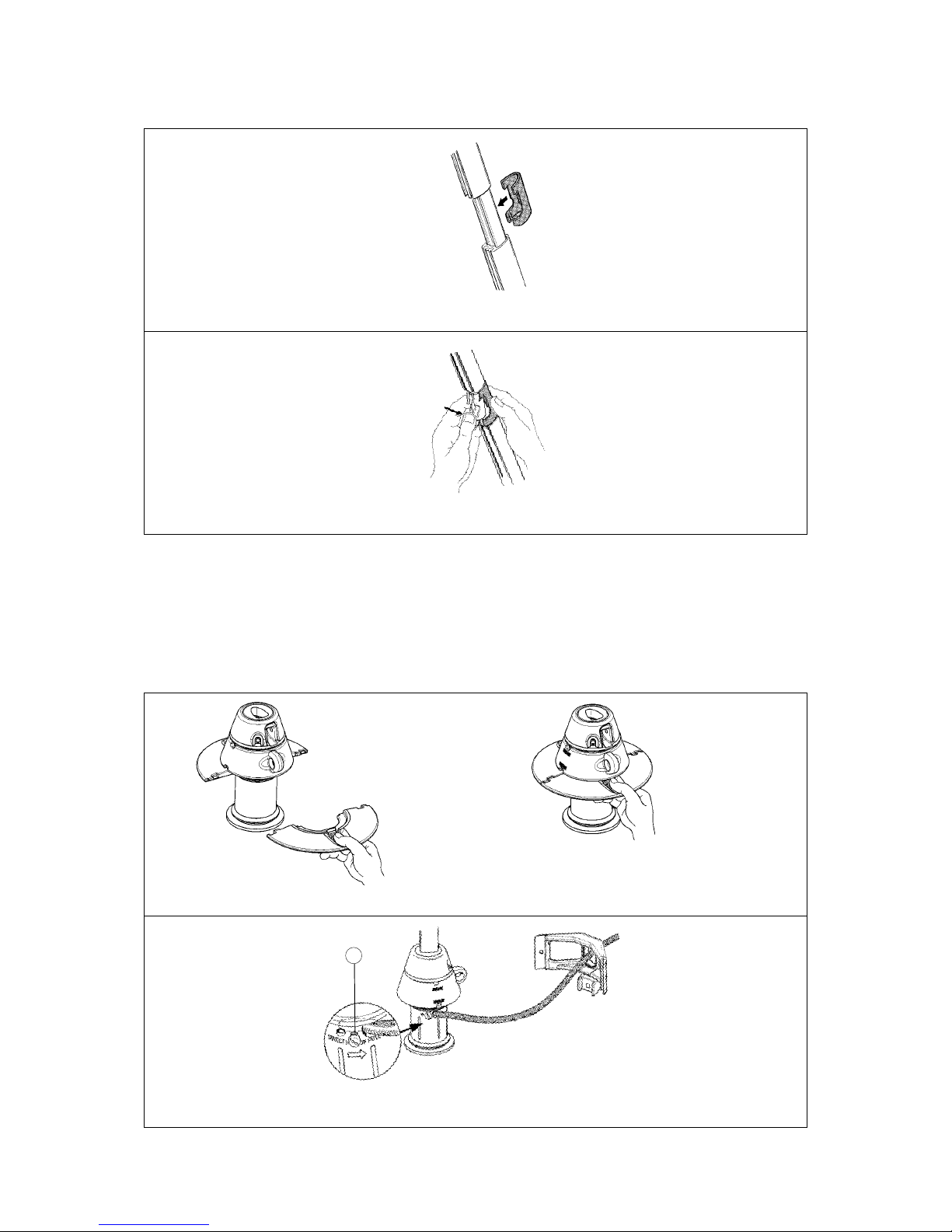
If the sail has a tendency to come out of the
pre-feeder, reduce the gap width by squeezing
the two arms toghether with a pair of pliers.
Max. 300 mm
Fig. 4.2.m
20
20.
21.
Installing the sail feeder:
22. We recommend fitting the Furlex system onto the boat at this stage.
See chap. 16, ”Rigging”.
Press on the sail feeder connector from the front of the luff extrusion.
Clip the sail feeder into the connector’s
top recess, then press the sail feeder’s lower edge until it snaps into place.
Fig. 4.2.n
Fig. 4.2.o
4.3 Fitting the line drum and line guide
These parts are easier to fit after the Furlex is fitted to the boat.
1.
2.
Fig. 4.3.c
Fit the two upper flange halves (with the labels) on the lower bearing.
Feed the furling line through the hole in the line guide fitting and into the oval hole in the lower
bearing assembly until it is just past the small sighting hole. Tighten the locking screw hard.
Fig. 4.3.a Fig. 4.3.b
1
Table of contents
Other Selden Marine Equipment manuals

Selden
Selden Furlex 200 S User manual

Selden
Selden Furlex 104S Guide

Selden
Selden Furlex 204S Guide

Selden
Selden Furlex 404S Guide

Selden
Selden Furlex 400 S Supplement

Selden
Selden Furlex Electric 200E User manual

Selden
Selden Furlex 200 TD User manual

Selden
Selden Furlex 200 S User manual

Selden
Selden Furlex 204TD User manual

Selden
Selden Furlex 404TD Guide

Popular Marine Equipment manuals by other brands

Ziton
Ziton ZP755W-2R Installation sheet

PRM NEWAGE
PRM NEWAGE PRM90 Workshop manual

PMG
PMG ULTRAGUARD Antifouling Master Series owner's manual

Furuno
Furuno LS-6100 Operator's manual

Jensen
Jensen MWR45 Installation & operation

Francis
Francis A7183 VX500 150w 115/230v Xenon User instruction & installation manual


