Selden Furlex 104S Guide
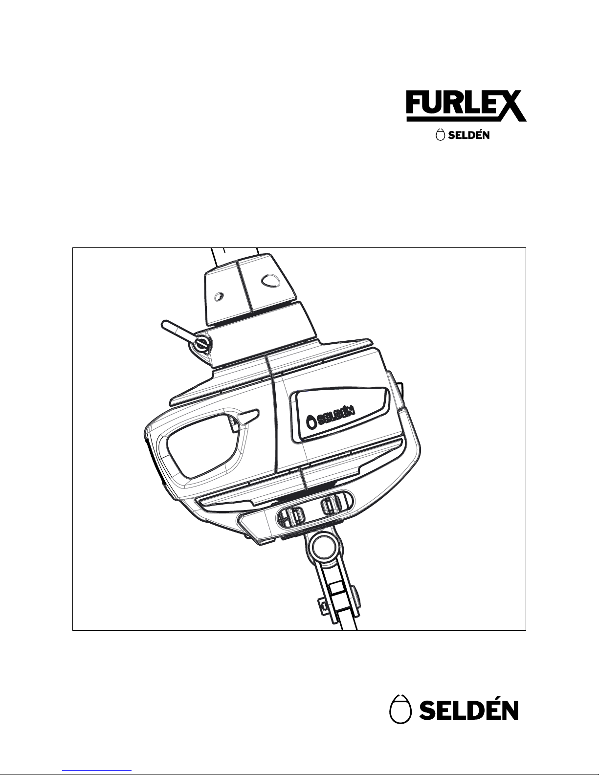
1
Manual and Spare parts list
Furlex
104S
597-133-E
2015-11-12
104S

2
Contents
Page
1 Introduction 3
1.2 What’s included? 4
1.3 Main dimensions 4
1.4 Safety precautions 5
1.5 Sail information 6
2 Assembly preparations 7
2.2 Mast and deck attachment 7
2.3 Wire length calculation 8
2.4 Top extrusions - length calculation 9
3 Assembly 11
3.1 Luff assembly 11
3.2 Fitting Sta-lok eye terminal 13
3.3 Fitting eye terminal to swaged 15
stud (Stud/Eye)
4 Installation 17
4.1 Mast attachment 17
4.2 Deck attachment 18
4.3 Installation on a stepped mast 19
4.4 Installation on an un-stepped mast 19
4.5 Furling line installation 19
4.6 Adjusting the forestay length 21
4.7 Checklist 22
5 Operation 23
5.1 Hoisting 23
5.2 Unfurling the sail 24
5.3 Furling the sail 24
5.4 Reeng 25
5.5 Racing 25
6 Maintenance 26
6.1 Inspection 26
6.2 Service 26
6.3 Storage 26
6.4 Dismantling 27
6.5 Troubleshooting 31
6.6 Spares & Accessories 33
6.7 Toggles & links 37
7 Warranty 38

3
1 Introduction
1.1 Key features
Congratulations on the purchase of your new Furlex jib furling system. Furlex jib furlers have been engineered
and manufactured by Seldén Mast since 1983. The system has been continuously developed over the years and
we are now launching the fourth generation Furlex, the most sophisticated single line jib furling system so far.
Maximized luff length
The luff extrusion foil shape remains unchanged all the way down the furling unit. This allows the whole sail
to be furled in an even roll - right down to the tack of the sail. This is essential to acheive an efcient sail shape
when the sail is reefed.
Load distributors
The patented load distribution technology of the Furlex system distributes loads over the entire ball race. This
reduces friction, provides smoother furling and considerably reduces bearing wear.
Compact halyard swivel
The all new halyard swivel design uses an HMPE textile loop that allows the halyard load to act in the centre of
the swivel instead of pulling on an offset eye. This reduces bearing loads and minimizes any wobbling tenden-
cies.
Low torque tack ring
The tack ring ”free turn” allows for the luff to be furled one turn before the tack. This makes for a atter and
more efcient sail shape when the sail is reefed. Reduced tack ring diameter in combination with a low prole
shackle – or an optional soft shackle – reduces the amount of effort needed to furl in that rst turn signicantly
compared to earlier models.
Soft shackle ready
The tack ring is prepared for using a textile loop instead of a stainless steel shackle. All surfaces are smooth and
nicely rounded.
Aero grooves
Similar to the dimples on a golf ball, the Furlex AERO groove system reduces drag and creates better
aero dynamic ow around the luff extrusion.
Third bearing
By the addition of a third roller bearing between the main ball bearings of the drum unit, the load from the
furling line is distributed over a large bearing area, reducing furling friction even further compared to earlier
models.
Floating connectors
The 316 stainless steel connectors are subjected to vertical loads only and no torsional loads.
Torsional loads are now taken by the join pieces alone which leaves the connectors “oating” inside the join
thus reducing wear inside the joins.
Air gaps
Every join in the system is made with a nominal gap which means the extrusion ends will never get in contact
with each other. This way there will be minimum chafe and no aluminum deposits staining on your new sail.
Mobile swivels
Both the halyard swivel and the drum unit can be easily removed from the foil for off-season storage. This
facilitates storing the foil with the mast and makes handling easier.
4
TED
TET
DD
DW DH
HO
Basic pack / Extended pack Foil pack Wire pack / Eye pack
• Drum unit
• Halyard swivel
• Furling rope
• Bearing halves
• Top guard
• Sail feeder
• Manual
Extended pack also includes:
• Halyard leads
• Stanchion blocks
• Prefeeder pack
• Torx bit set
• Luff extrusions
• Distance tubes
• Joining sleeves
• Connecting plates
• Wire with swaged eye
• Eye terminal (with or
without rigging screw)
Basic pack / Extended pack
The Furlex system consists of a basic pack with drum unit, halyard swivel, sail feeder, bearing halves, top guard
and furling rope. The Extended pack also includes halyard leads, stanchion blocks and prefeeder pack -
accessories that will make your system work even better on your boat.
Foil pack, wire pack and eye pack
The Furlex system also includes a foil pack with luff extrusions, distance tubes and connectors. A complete
forestay is also supplied with every Furlex, including a swaged stud/eye solution (no adjuster) or a Sta-Lok eye
terminal tting which may come with or without rigging screw. On new boats delivered with a complete new
Seldén rig, the forestay is usually included in the standing rigging and does not come as a separate wire pack.
1.2 What’s included?
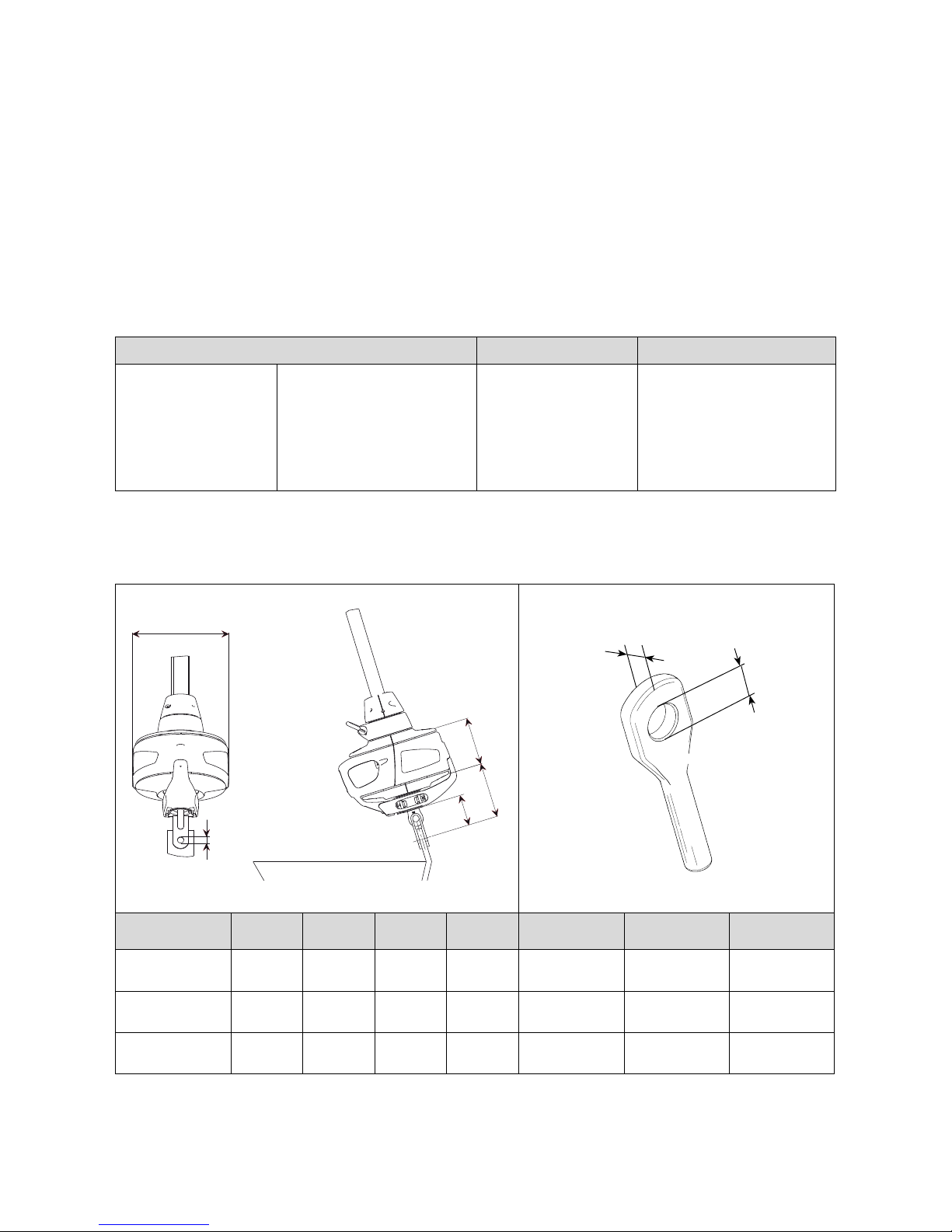
All dimensions are given in millimeters and inches.
1.3 Main dimensions
Pin
Wire dim. DD DH DW HO Pin TED TET
Ø4
(5/32”)
Ø155
(6 7/64”)
85
(3 11/32”)
65
(2 9/16”)
40
(1 37/64”)
Ø8
(5/16”)
Ø8.5
(21/64”)
4.5
(11/64”)
Ø5
(13/64”)
Ø155
(6 7/64”)
90
(3 35/64”)
65
(2 9/16”)
45
(1 49/64”)
Ø10
(25/64”)
Ø10.5
(13/32”)
5.3
(13/64”)
Ø6
(15/64”)
Ø155
(6 7/64”)
100
(3 15/16”)
65
(2 9/16”)
55
(2 11/64”)
Ø10
(25/64”)
Ø12.5
(31/64”)
7.0
(9/32”)
Fig. 1.3.b
Fig. 1.3.a
Pin
5
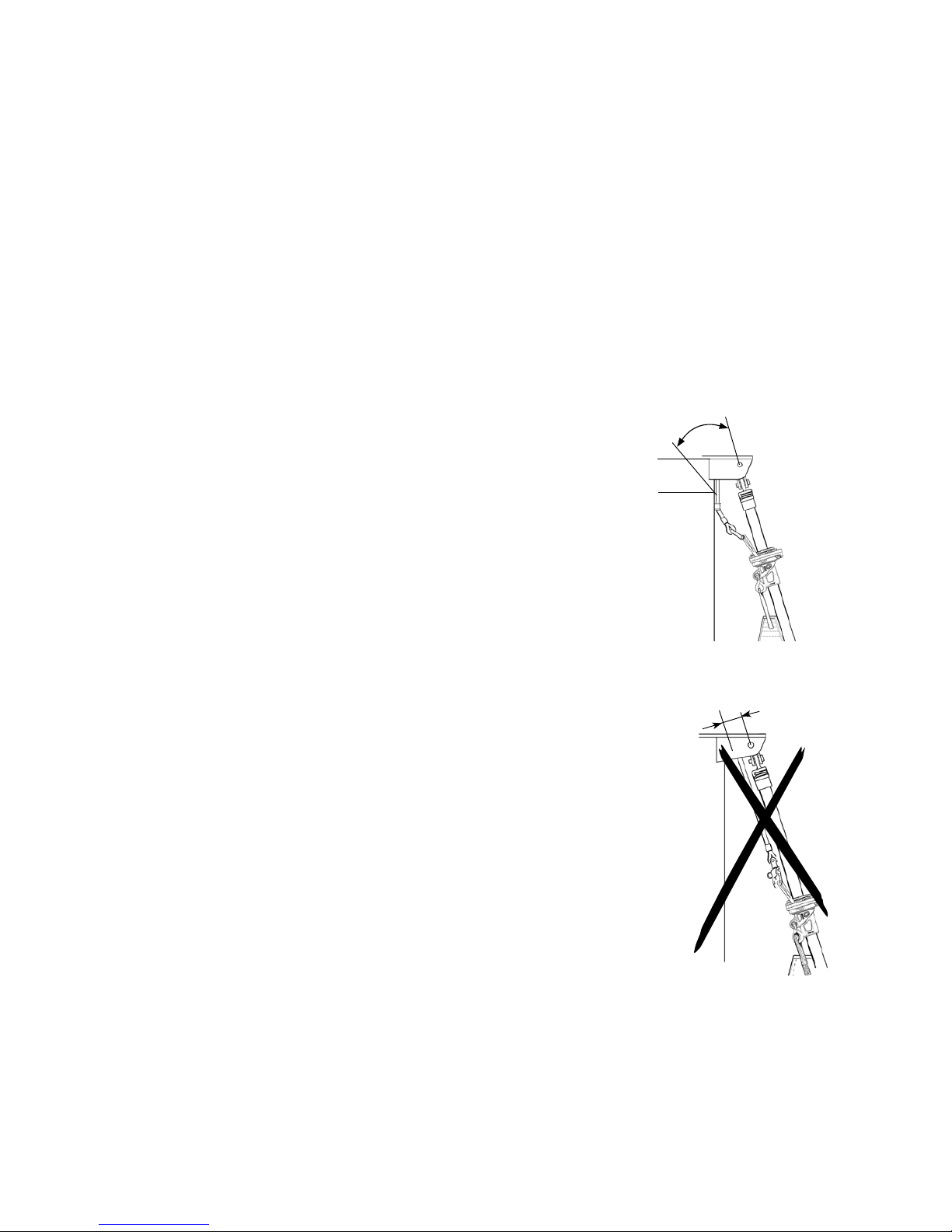
15-20°
The information in this manual must be followed carefully to avoid damage
to the system and to aviod the risk of personal injury. The warranty is only
valid if the system is assembled and operated according to this manual.
Please read the entire manual before assembly!
• Be very careful when you open the wire coil! It may spring open and
cause damage and/or personal injury.
• Never use a snap shackle to secure the standing rigging, not even tempo-
rarily. When installing the system on a rigged boat, always use a strong
screw pin shackle or tie the spinnaker halyard to a strong point on the boat
before removing the existing forestay.
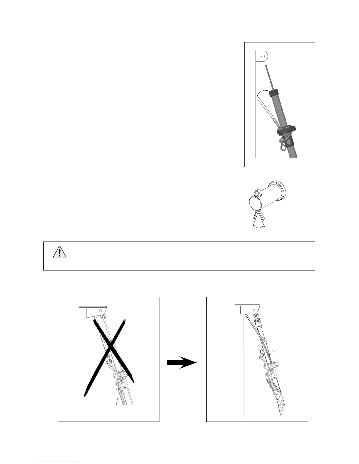
• Incorrect halyard routing can result in ”halyard wrap” which may cause
severe damage to the forestay, and put the entire rig at risk. The angle
between the halyard and the forestay must never be less than 15°. In-
correct halyard routing can also cause the halyard shackle to wear against
the luff extrusion.
• If using a winch for the furling line, rst check that there is no obstruction
which may interrupt the furling operation and possibly cause damage.
• Take care to ensure that all split pins are secured properly after installa-
tion.
1.4 Safety precautions
Fig. 1.3.cFig. 1.3.b
Fig. 1.3.d
Fig. 1.3.a
May lead to
Incorrect halyard routing can result in ”halyard wrap” which may cause severe damage to
the forestay, and put the entire rig at risk. The angle between the halyard and the forestay
must never be less than 15°!
6
FL
1100 mm
CB
E
F
Furlex type Ø4 & 5 Ø6
Head deduction F 440 (17 21/64”) 440 (17 21/64”)
Tack deduction E
(Any additional toggle or link
must be added to E) 205 (8 5/64”) 220 (8 21/32”)
Cutback CB 60 (2 23/64”) 60 (2 23/64”)
Internal diameter of luff groove
DLG Ø6 (15/64”) Ø6 (15/64”)
Width of luff groove WLG 2.75 (7/64”) 2.75 (7/64”)
Overall luff extrusion
dimensions
30x20
(1 3/16” x 25/32”)
30x20
(1 3/16” x 25/32”)
Your sailmaker has all the necessary sailmaker information through the Seldén Sailmakers guide. The
Sailmakers guide can be downloaded from www.seldenmast.com
Note that if you want to use an existing sail, it will need some modications.
• The luff length needs to be adjusted.
• A luff tape is required. The luff tape must be compatible with the Furlex luff extrusion geometry.
• Use webbing loops at the sail head and tack instead of grommets (cringles). The sail will then form tightly
round the luff extrusion when furling, and achieve a better shape when reefed.
1.5 Sail information
Fig. 1.5.a
Fig. 1.5.c
It is most important that the halyard swivel is located so that the halyard satises the 15–20°
angle requirement. If the sail prevents the swivel from reaching the
correct position, the luff length needs to be adjusted.
IF THE SAIL IS TOO LONG: Shorten the sail, e.g. in conjunction with changing to a luff
tape compatible with Furlex.
IF THE SAIL IS TOO SHORT: Lengthen the sail by means of a HMPE or wire pendant
tted to the head of the sail. Attach the pendant directly to the sail to prevent unintentional
removal, loss or exchange.
Fig. 1.5.b
Luff groove
Luff tape
chamber
Max sailspace FL -(F+E)
7
2 Assembly preparations
2.1. Tools
2.2 Mast and deck attachment
Before starting with the assembly, make sure you have the following tools available:
• Socket screw driver
• Hack saw
• Torx bits
• Measuring tape
• Knife
• Hammer
• Pencil
If Sta-lok is to be tted you will also need:
• Two adjustable spanners
• Polygrip
• Tape
• File
• Locking adhesive (included in the eye tting pack)
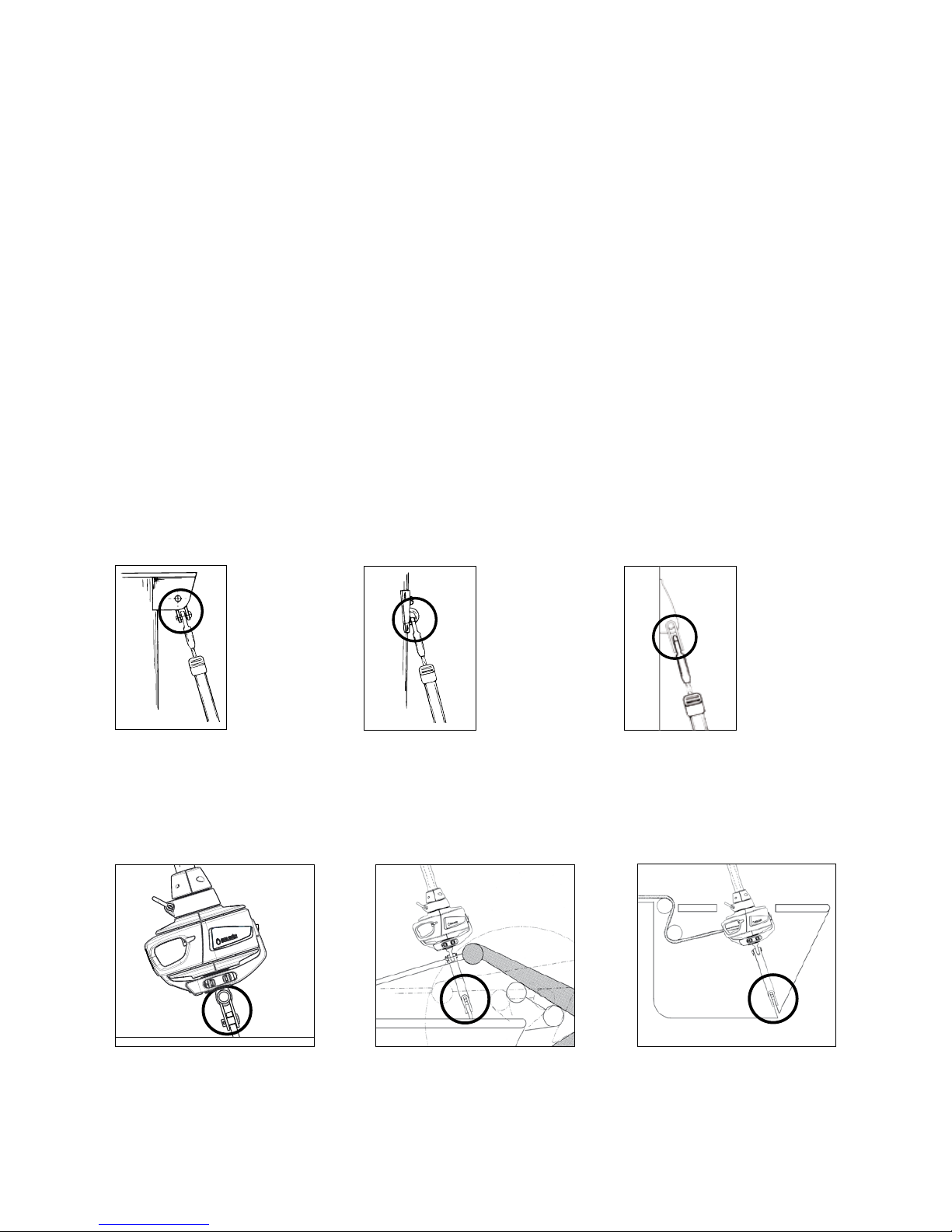
Always make sure that the forestay can articulate in all directions, both in the top and at deck level. Toggles
must be used in most cases to ensure sufcient articulation.
The toggle on the furling unit should always be tted directly to the chain plate. If the unit is to be tted below
deck or if it needs to be raised, an extension toggle can be used but always make sure that the toggle that
comes with the drum unit is attached to the chain plate.
For available toggles and extension links, see “Spares and accessories”.
Fig. 2.2.a
Fig. 2.2.d Fig. 2.2.e Fig. 2.2.f
Fig. 2.2.b Fig. 2.2.c

8
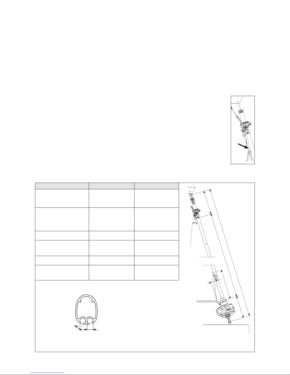
2.3 Wire length calculation
1. Slacken the backstay and/or the cap shrouds as much as possible, but make sure that no rigging screws are
unscrewed so far that the threads are no longer visible ”on the inside” of the rigging screw body. The
forestay setting should not be adjusted. Ideally the forestay setting should not be adjusted. However, if there
is insufcient adjustment in the backstay, and the forestay has a rigging screw, this can be adjusted as well.
Just make sure to mark the thread with tape before adjusting.
2. Pull the top of the mast forward using the genoa or spinnaker halyard. Secure the halyard using a ”D”
shackle or tie the halyard to a strong deck tting. For safety reasons, do not use any halyard snap shackles.
Secure the halyard tail after the halyard has been tensioned.
3. Go up the mast. Connect a free halyard to the forestay. Then detach the forestay and lower it using the free
halyard. Bring the stay down and place it on a at surface. If the forestay rigging screw was slackened,
adjust it back to the tape mark.
4. Measure the forestay length (FL) with just enough tension to keep the forestay straight on the ground.
Forestay length (FL) is the distance between the hole in the swaged top terminal and the hole in whatever
lower part that was attached directly to the hole in the chain plate. Enter the measurement into
”Table 1” below, in the row marked FL.
If a Sta-lok terminal (with or without rigging screw) is included, the wire is supplied over-length. The wire has
a swaged eye terminal on one end while the other end is open (= without terminal). If your Furlex is supplied
with a xed-length forestay, with a swaged eye on one end and a swaged stud in the other end, skip this part
and go directly to 2.4.
If a stud-terminated stay is to be manufactured by a local rigger it is important to note that WL in this case
equals the length of the nished stay, from eye to end of stud, as shown in g. 2.4.a. WL is calculated in table 1.
Before assembly, an over-length wire (for Stalok) must be marked and nally cut to the correct length to t the
boat’s actual forestay length. To nd out the correct measurement, follow the steps below. If the mast is not
stepped, you can jump directly to step 4.
You can use the FURLEX CALCULATOR on our web site. Go directly to the calculator by
scanning the QR-code with your mobile device or visit www.seldenmast.com.
Table 1: Calculation of forestay wire cutting length Your
forestay
Example
(104S/Ø5)
with rigging screw
50% extended
FL Existing forestay length (FL), including rigging screw (See g. 2.4.a) 10 000
TDeduction for lower terminal - - 150
HIf links or extra toggles are to be used, deduct this length (H) from FL.
(See table 6.7).
- - 0
WL Cutting measurement. The new forestay wire is to be marked at this point.
(For stays with swaged stud, WL equals the length of the nished stay as
shown in g 2.4.a. and NOT the cutting length)
= = 9850
WIRE Without rigging screw: With rigging screw:
104S Ø4 mm wire: 60 mm (2 23/64”)
Ø5 mm wire: 65 mm (2 9/16”)
Ø6 mm wire: 75 mm (2 61/64”)
Ø4 mm wire: 147 mm (5 25/32”)
Ø5 mm wire: 150 mm (5 29/32”)
Ø6 mm wire: 155 mm (6 7/64”)

9
A
E
200
CB
D
WL T
2.4 Top extrusions - length calculation
The Furlex luff extrusion consists of a number of shorter pieces. Starting from the bottom there is a 1000 mm
luff extrusion connected to the drum unit and extending up to the sail feeder. Then, from the sail feeder and up
there are a number of full length luff extrusions (L=2400 mm) and nally there is a top extrusion that has to be
cut to length to suite the actual forestay length.
Note! If the calculation gives a top extrusion length (D) that is shorter than 400 mm, the
calculation must be reworked by exchanging one of the 2400 mm (94 1/2”) extrusions with
the uncut 2000 mm (78 47/64”) top extrusion. By doing so the top extrusion will be cut from
a 2400 mm length and its length will then exceed 400 mm (15 3/4”). If the calculation gives
a top extrusion length (D) that exceedes 2000 mm (78 47/64), the top extrusion must be cut
from one of the 2400 mm (94 1/2”) extrusions. In this case the 2000 mm (78 47/64) extrusion
will not be used.
Fig. 2.4.a
FL = existing forestay length

10
To nd out the cutting length of the top extrusion (D) and the length of the top distance tube
(E), start with the length of the forestay wire (WL) that was calculated in table 1. Then
follow the steps in table 2 below. On xed length forestays, verify WL by measuring the
stay length from centre of eye to end of stud (wire).
You can also use the FURLEX CALCULATOR on our web site. Go directly to the
calculator by scanning the QR-code with your mobile device.
Table 2: Calculation of top luff extrusion length and top distance tube length Your forestay
Example
(104S/Ø5)
with rigging screw
50% extended
WL Length of the new forestay wire (as per Table 1). 9850
A+B 1190
NNumber of full length extrusions to be used:
N = ( WL - (A+B) ) / 2400 (94 1/2”)
(9850-1190)
/2400=3.6
N=3
CTotal length of the number of full length extrusions (2400 mm) to be used:
C = N x 2400 (94 1/2”)
3 x 2400 =
7200
D* Length of top luff extrusion:
D = WL – (A+B) – C
9850-1190
-7200 = 1460
E* Length of the top distance tube:
E=D-200 (7 7/8”)
1460-200 =
1260
WIRE Without rigging screw: With rigging screw:
104S Ø4 mm wire: 1260 mm (49 39/64”)
Ø5 mm wire: 1275 mm (50 13/64”)
Ø6 mm wire: 1290 mm (50 25/32”)
Ø4 mm wire: 1175 mm (46 17/64”)
Ø5 mm wire: 1190 mm (46 27/32”)
Ø6 mm wire: 1210 mm (47 41/64”)
*) If D becomes less than 400 mm it is necessary to recalculate as below and cut one of the full length luff
extrusions according to Dnew and one of the full length distance tubes according to Enew.
Note that the original top luff extrusion and the original top distance tube will now be used as intermediate
extrusions.
Table 2B: Recalculation if D<400 mm Your forestay Example
Nnew Reduce the number of full length extrusions by one.
Nnew = N-1
Cnew Cnew = Nnew x 2400 + 2000 (94 1/2” + 78 47/64”)
Dnew Dnew = D + 400 (15 3/4”)
Enew Enew = E + 400 (15 3/4”)
11
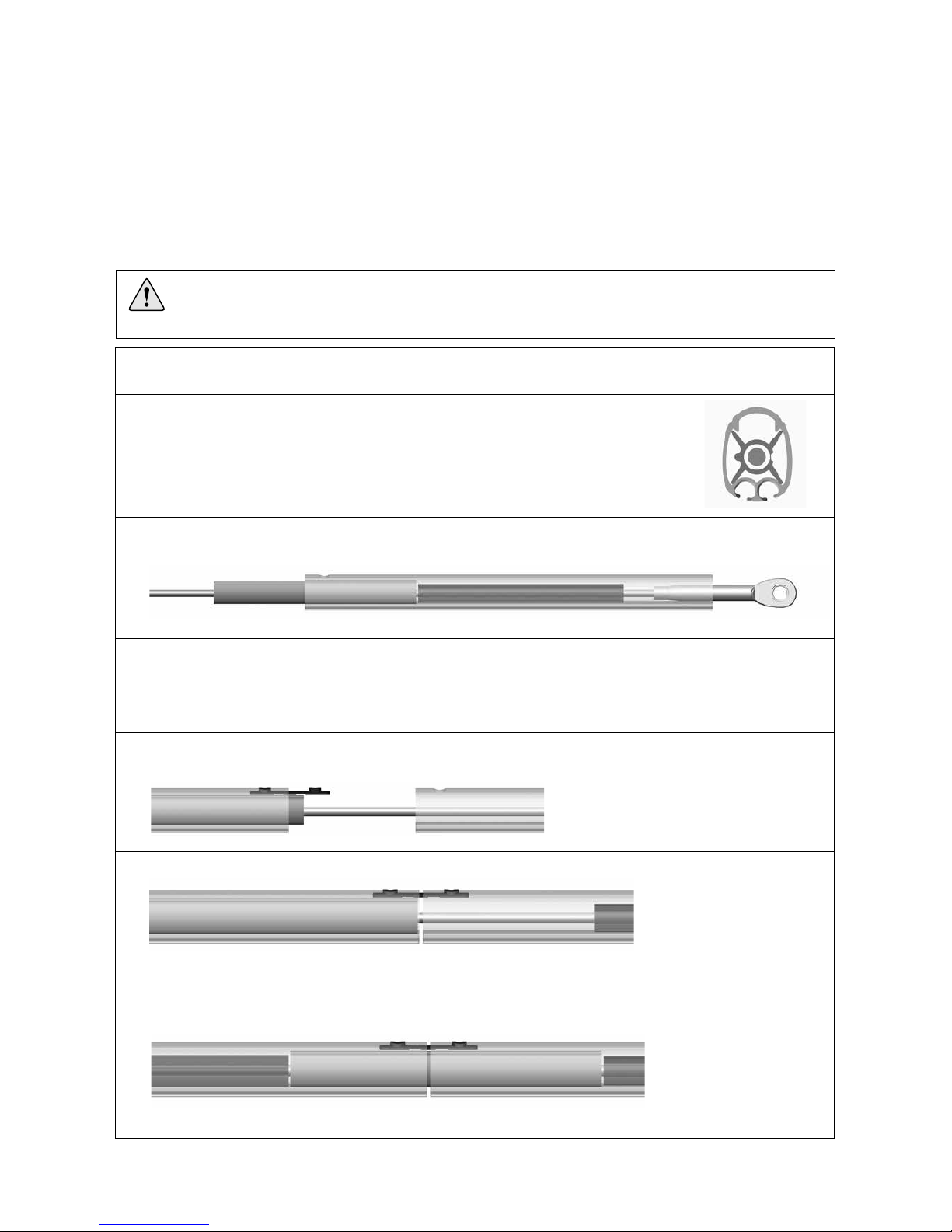
1. Stretch out the wire on a at, clean surface. On stays with swaged lower terminal, be careful not to
damage the terminal thread. The thread can be protected with tape or similar.
2. Start by feeding the top luff extrusion and the top distance tube onto the forestay wire.
The distance tubes are welded shut but are easily opened by hand. Note the correct
orientation of the distance tube - hinge to be sideways.
3. Add a short joining sleeve and use it to push the distance tube up into the top luff extrusion. The
distance tube should be pushed in approximately half the length of a joining sleeve.
4. On Sta-lok terminated systems, the halyard swivel and the top guard can be tted at this point, see
below. On stud terminated systems, the top guard must be tted after the sail feeder has been mounted.
5. Add another luff extrusion and another distance tube. Make sure the distance tube is oriented correctly. Also
add another short joining sleeve.
6. Fit a short connecting plate into the second luff extrusion as shown. Push the rst joining sleeve down
into the second luff extrusion to lock the connector.
7. Connect the two luff extrusions.
8. Push the rst joining sleeve back up into the rst luff extrusion to lock the join. Use the second joining
sleeve to push on the second distance tube. The second distance tube should be pushed in approximately
half the length of a joining sleeve. This will ensure correct location of the rst joining sleeve.
3 Assembly
3.1 Luff assembly
Luff assembly should be carried out on a clean, at surface. Make sure there is enough space for the entire
forestay length to be stretched out.
At this point the top luff section and the top distance tube should be cut to length according to table 2.
Notethattheluffextrusionsarettedontothewire,whereasonoldersystemsthewirewas
ttedasalaststep.Alsonotethattheluffisassembledfromtopdownasopposedtoolder
systems.
Fig. 3.1.a
Fig. 3.1.c
Fig. 3.1.d
Fig. 3.1.e
Fig. 3.1.b

12
9. Repeat for the remaining 2400 mm (94 1/2”) luff extrusions. Use short joining sleeves only.
10. Fit the long joining sleeve onto the wire. Then t the short distance tube and nally the short 1000 mm
(39 3/4”) luff extrusion. Make sure that the small hole end goes rst.
11. Connect the same way as previous joins but use the long connector this time. Push the short distance
tube in approximately 40 mm (1 37/64”), leaving space for the bearing plug halves, see below.
12. Snap on the sail feeder connector and put the sail feeder in position.
13. Fit the halyard swivel from the top and slide it down until it stops on top of the sail feeder. Then t
the top guard and push it into the top luff extrusion until it stops. Secure it with the two pre-tted
screws. Tighten the screws until they bottom, but do not over-tighten.
14. Fit the bearing plug halves as shown. Adjust so that the hole in the forward bearing plug aligns with the
forward hole in the 1000 mm (39 3/4”) luff extrusion.
This completes the luff assembly. Next step is to t the lower eye teminal to the stay. There are two types of eye
terminals; Stud/Eye terminal and Stalok eye terminal (with or without rigging screw).
Fig. 3.1.g
Fig. 3.1.h
Fig. 3.1.i
Fig. 3.1.f

13
2 mm
WL
1.
Before cutting the wire, measure the wire from the centre of the hole in the top swaged eye terminal. Mark the
measurement WL carefully on the wire using a marker pen. (The WL measurement was calculated in ”Table
1”, (Chapter 2.3).
2. Put adhesive tape around the wire on both sides of the cutting mark to assist cutting.
3 .
Unscrew the socket, wedge and former from the terminal part (or Furlex rigging screw if to be used).
4.
Thread the socket onto the wire.
5.
Slide the wedge over the core (7 strands) of the wire. The core of the wire should protrude approx. 2 mm
(5/64”) from the wedge.
3.2 Fitting Sta-lok eye terminal
Note! For systems with swaged stud terminal, skip this part and go directly to 3.3.
Fig. 3.2.b
Fig. 3.2.c
Former Wedge Socket
Terminal part (or rigging screw)
Fig. 3.2.d
Fig. 3.2.a

14
6 .
Space the outer strands of the wire evenly around the wedge and bring
down the socket so that the strands are held in place. Hold an adjustable
spanner between the 1000 mm (39 3/8”) extrusion and the socket.
Tapping the core of the wire, locate it firmly in the socket.
Check that the core of the wire protrudes approx. 2 mm (5/64”) from the
wedge. See fig. 3.2.d.
7.
Bend the outer strands inwards a little using a pair of pliers, or tap the
strands with a small hammer. In the latter case, rest the socket’s thread
on a soft surface (wood or similar) to prevent damage.
8.
Insert the former into the threaded hole of the terminal part (or rigging screw). Lubricate the socket´s thread
with a long bead of locking adhesive. Screw the terminal part onto the socket and tighten carefully, forcing
the wire further into the terminal.
9.
Unscrew and check that the outer strands are evenly
distributed around the wedge. If some strands are
crossed, correct their positions.
10.
If assembly is unsuccessful and needs to be repeated, refer to the relevant parts of extrusion 6.4
”Dismantling”.
11.
Apply another 2 or 3 drops of the locking adhesive to the
thread and screw the terminal together, tightening it firmly.
The terminal is now permanently locked.
NOTE! Check that no strands slip into the slot of the wedge.
Fig. 3.2.e
Fig. 3.2.h
Fig. 3.2.g
Fig. 3.2.f
NOTE! Check that no strand has slipped into the slot of the wedge!
15
3.3 Fitting eye terminal to swaged stud (Stud/Eye)
Fig. 3.3.a
Fig. 3.3.b
Fig. 3.3.c
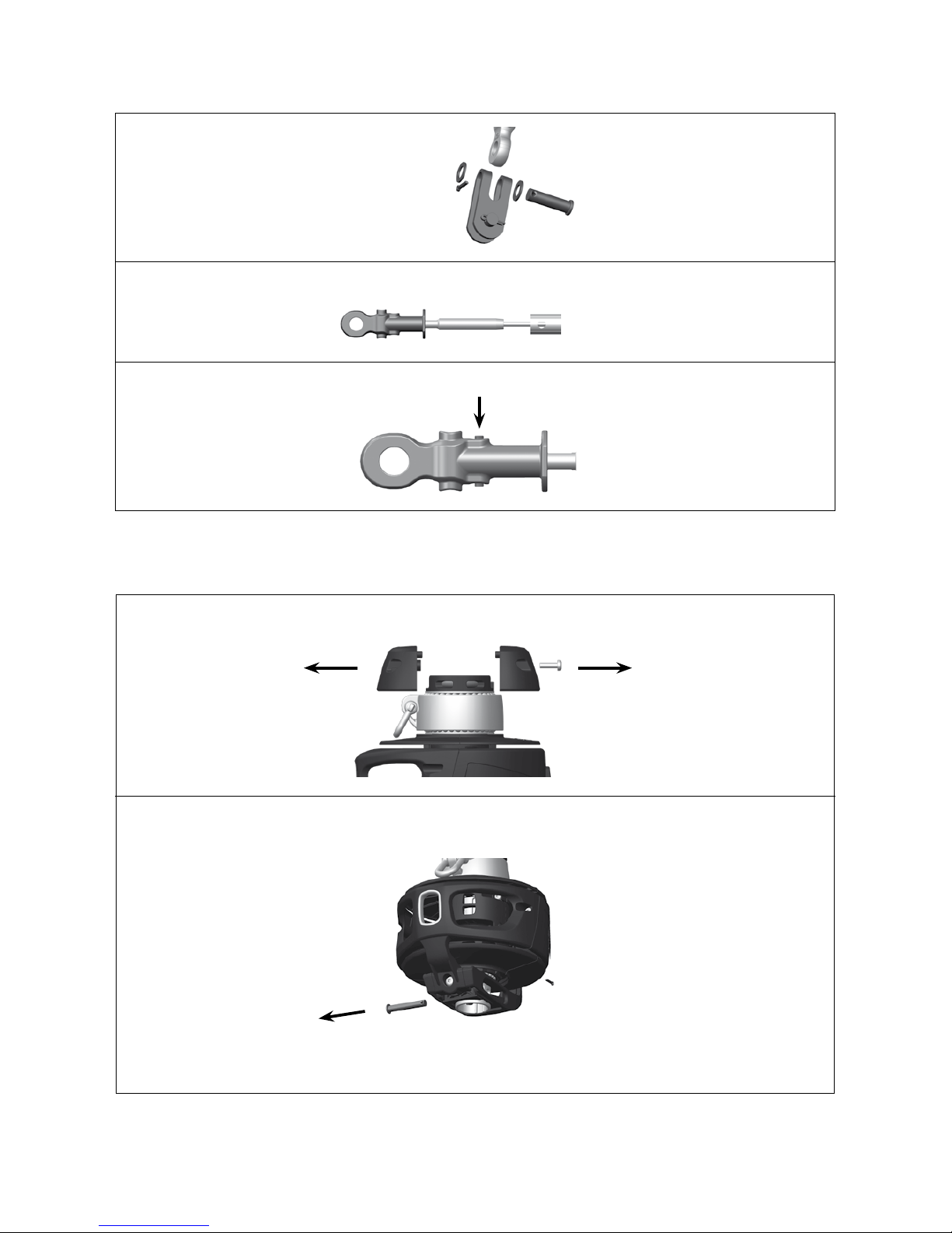
1. Remove the toggle from the eye fitting.
2. Screw the eye terminal part onto the stud terminal until the holes in stud and eye align.
3. Fit the spirol spring pin using a hammer to permanently lock the terminal.
3.4 Drum unit assembly
1. Unscrew the two screws holding the adaptor halves together. Take care not to loose the the screws.
2. Remove the clevis pin that goes through the tube shaft in the drum unit.
Fig. 3.5.a
Fig. 3.5.b
16
20°
20°
Fig. 3.5.eFig. 3.5.dFig. 3.5.c
Fig. 3.5.g
Fig. 3.5.i
Fig. 3.5.h
3. Fit the drum unit over the eye terminal. Orient the drum unit so that the at surface on the eye
terminal meets the two ribs inside the drum unit tube shaft.
If a Furlex rigging screw is used, the at faces on all three components must be aligned. As the two ribs
on the inside of the tube shaft matches the at faces, it will securely lock the rigging screw.
When tting the drum unit, the rigging screw should be unscrewed halfways.
Ret the clevis pin through the tube shaft and the hole in the eye terminal. Secure with the split pin.
4. Fit the adaptor halves. The round boss in the forward adaptor half ts into the hole in the luff extrusion
lower end. Note that the halves can be tted one way only.
Best practice to t the adaptor hlaves is to start by pushing the forward adaptor half onto the luff
section and then connect to the upper hub . When the forward half is in postion, t the aft half
and click the halves together. Make sure that the screws go in smoothly so that the screw threads are not
damaged.
Tighten the screws rmly.
5. Ret the toggle. Secure the split pin.
17
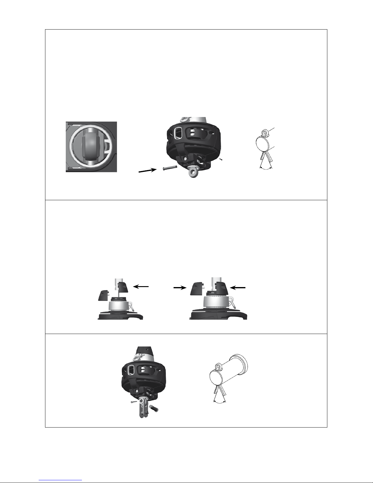
0–10°
15–20°
4.1 Mast attachment
4.1.1 Halyard routing
The guiding principle for tting the Furlex to the mast is that the forestay connection should allow sufcient
articulation in all directions. In most cases a toggle must be tted between the Furlex stay and the forestay
attachment. For available toggles and extension links, see extrusion “Spares & accessories”.
The angle between the halyard and the forestay must be at least 15°. If the
angle is less than 15°, the halyard may wrap around the luff extrusion when
the sail is being furled, possibly damaging the halyard and the luff extrusion.
Failure to observe what is happening in this situation may even result in
damage to the forestay wire.
Before installing the Furlex on the boat, make sure that the 15–20° require-
ment is fullled. On new Seldén masts this is usually not an issue but on older
masts - or masts of other brands - it may be necessary to t halyard leads or to
t a new halyard box.
The Extended Pack includes two halyard leads. These are easy to install and
t on most mast brands. Halyard leads should be inspected once a year and
any sharp edges smoothed with a le. The halyard lead should be replaced
when wear reaches 50%.
Alternatively, a sheave box can be tted to the mast to meet the 15–20°
requirement. Installation is more complicated but the box will eliminate the
need to replace the halyard leads as they wear. Sheave box kits (with assembly
instructions) can be obtained from your Seldén dealer.
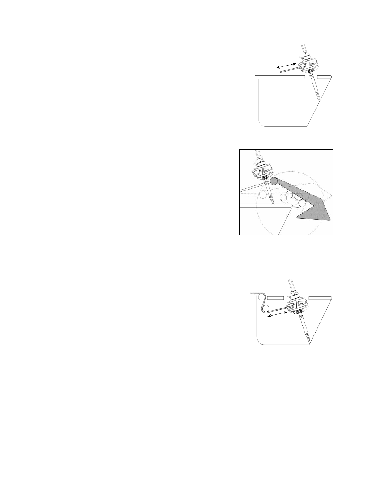
If the boat is equipped with a spinnaker halyard, this must be kept clear of the
Furlex-system when not in use to avoid halyard wrap. An effective solution
is to lead the halyard around the upper shroud and then down aft of the
spreaders.
4 Installation
Installation of the Furlex system on the boat requires a minimum of two persons, however it is recommended to
be at least three persons to do the job more easily.
Fig. 4.1.1.a
Fig. 4.1.1.b
18
Min. 300 mm
Min. 300 mm
4.2 Deck attachment
4.2.1 Attachment below deck
The lower end of the Furlex-system comes with a fork toggle
as standard. This can normally be attached directly to the boat’s
forestay tting at the stemhead. Check that the drum unit does not
interfere with the pulpit, navigation lights or other deck ttings.
For the furling line to be wound evenly onto the line drum, the rst
turning point (stantion block) must be at least 300 mm (11 13/16”)
away. The tack should be located as close to deck level as possible.
If the boat is tted with a bow anchor, it may be necessary to
permanently raise the drum unit to give the crew sufcient space for
anchor work.
If the drum unit is raised by means of an extension link, a toggle
must be tted between the link and the boat’s forestay attachment at
the stemhead.
For available toggles and extension links, see extrusion “Spares and
accessories”.
The furling unit can be tted below deck inside an anchor well. The
advantage is that the sail’s luff length is maximized and the access
around the forestay is improved. The disadvantage is a more
complicated route for the furling line resulting in increased furling
resistance. The diagrams below illustrate various methods of
installation.
Regardless of which option is chosen, the Furlex-system must
always be kept clear of the deck well’s inside surfaces.
Avoid routing the line through an integral deck conduit, as this will
increase the friction on the furling line.
Use a large ball bearing block to minimize friction losses.
The anchor well must be well drained.
If the Furlex is tted above deck, but with the forestay tting in the
anchor well, a Furlex extension toggle can be used. For larger
distances, use a custom made stainless steel bar or rod stay. For
available toggles and extension links, see extrusion “Spares and
accessories”.
Fig. 4.2
Fig. 4.2.1.a
Fig. 4.2.1.b

19
4.3 Installation on a stepped mast
4.4 Installation on an un-stepped mast
1. Lay the dressed mast on trestles with the front facing up.
2. Connect the top end of the Furlex-system to the forestay attachment on the mast. Make sure that the stay is free
to move in all directions.
3. Lift the mast in the crane with the Furlex-system lying on the leading edge of the mast.
4. Have one person watching the Furlex-system to ensure that it does not get caught when lifting the mast.
5. Keep the end of the stay outside the deck area in order to avoid damage.
6. Attach the stay to the chain plate in the boat at the stemhead. Make sure that the stay is free to move in all
directions.
Fig. 4.3
4.5 Furling line installation
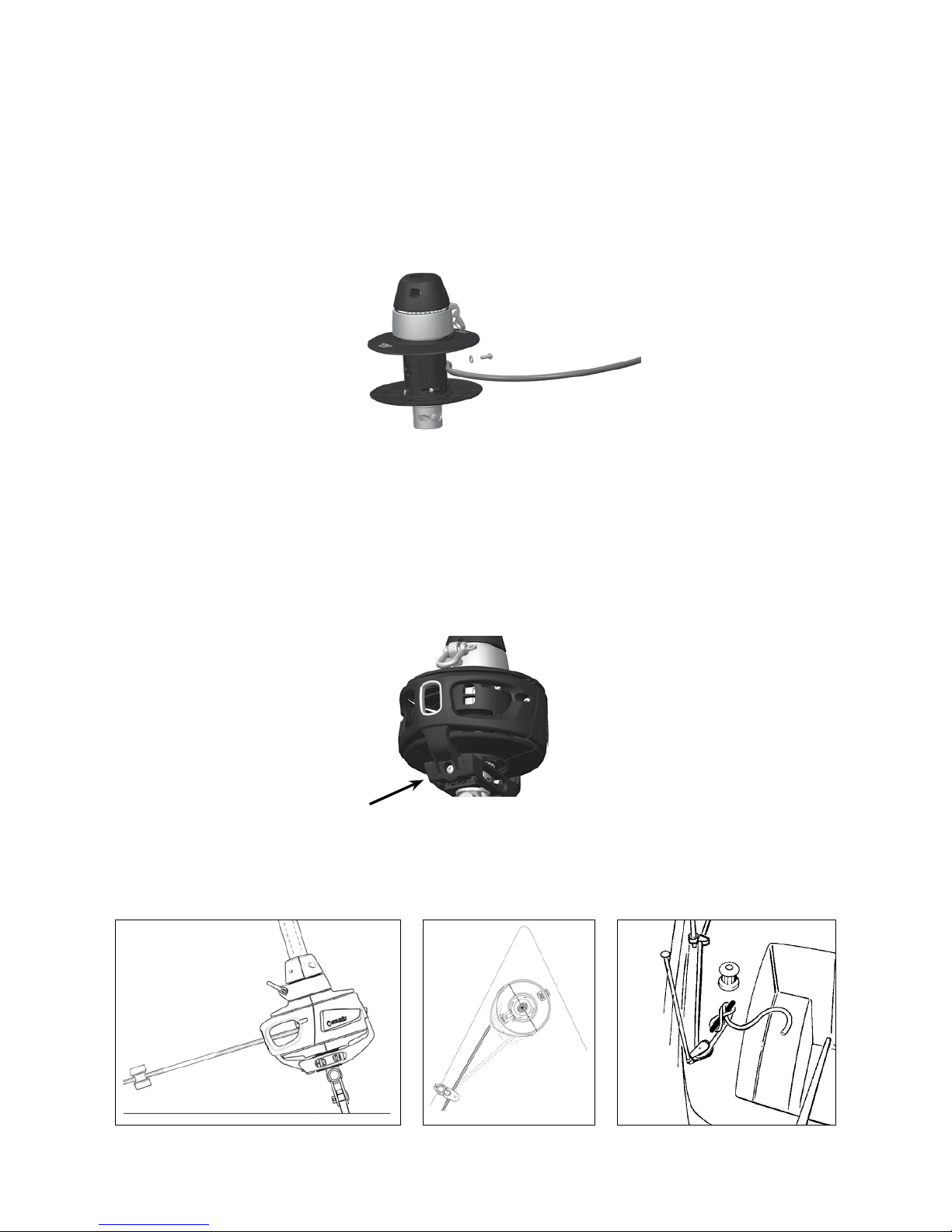
1. Start by loosening the screw on the underside of the drum unit a few turns. Then loosen the two smaller
screws on each side of the line guide tting until the line guide tting and cover seperates. Remove the line
guide tting. It may be necessary to loosen the screw on the underside a few extra turns for the line guide
tting to come off.
2. Pull out the lock block.
3. Remove the cover.
4.5.1 Removing line guide fitting and cover
Fig. 4.5.1.a Fig. 4.5.1.b Fig. 4.5.1.c
1. Slacken the backstay as much as possible, but do not remove it.
2. Pull the mast forward using a genoa halyard or a spinnaker halyard. Secure the halyard to a strong deck
tting using a screw pin shackle or tie the halyard to a strong deck tting. For safety reasons, do not use
snap shackles.
3. Tie a strong, not too stiff, rope around the luff extrusion. Make two clove hitches and tape the knots over
carefully so that they cannot slide.
4. Hoist the stay using a spare halyard.
5. ”Go aloft” and attach the top end of the Furlex-
system to the forestay attachment. Always use a
proper bosun’s chair. If there are no free headsail
halyards, use the main halyard. For further information,
see the ”Working aloft” section in the brochure
”Hints and Advice” that can be downloaded on
www.seldenmast.com.
6. Finally attach the stay to the forestay attachment in the boat at the stemhead.
The furling line is best tted to the drum unit with cover and line guide removed.
20
To wind the line onto the drum, turn the luff extrusion by hand and wind approx. 30 turns onto the line drum.
Wind the line onto the drum before hoisting the sail.
The line should be led aft to the cockpit via lead blocks. Lead blocks are included in the Extended Pack. The
lead blocks are normally mounted on the pulpit and on the stanchions leading the line back to cockpit.
The forward lead block is tted so that the furling line exits the line guide tting in a straight line. Ease the
screw on the underside of the drum unit a little to be able to make the adjustments. Also adjust the line guide
and cover height so that the drum is allowed to rotate freely. Tighten the screw rmly when nished.
The nal turning block by the cockpit needs to be matched individually to each boat depending on the
attachment points, the line arrangement chosen and possibly also the type of other blocks on the boat. We
recommend a swivel block which is free to self-align. The maximum working load of the block should not be
less than 3000 N (300 kg/ 660lb).
Fig. 4.5.2.c Fig. 4.5.2.d Fig. 4.5.2.e
If the sail’s ultraviolet (UV) protection is tted on the starboard side of the sail, the furling line should exit on
the port side of the line drum. If the UV protection is tted on the port side, the furling line should exit on the
starboard side of the line drum.
Use an awl or similar tool to make a hole in the rope 10-15 mm (25/64” - 19/32”) from the rope end and t the
screw through the hole. Make sure that the washer is tted under the screw head, then tighten the screw rmly.
Use locking adhesive on the screw thread. Ret cover and line guide by doing a reverse dismantling, see pre-
vious section.
4.5.2 Fitting the furling line
Fig. 4.5.2.a
Fig. 4.5.2.b
Table of contents
Other Selden Marine Equipment manuals

Selden
Selden Furlex 200 TD User manual

Selden
Selden Furlex Electric 200E User manual

Selden
Selden Furlex 404TD Guide

Selden
Selden Furlex Electric 200E User manual

Selden
Selden Furlex 200 S User manual

Selden
Selden Furlex 400 S Supplement

Selden
Selden Furlex 204S Guide

Selden
Selden Furlex 204TD User manual

Selden
Selden Furlex 404S Guide

Selden
Selden Furlex 200 S User manual


