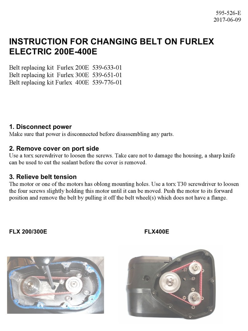
Selden Furlex Electric 200E User manual

1
595-926-E
2015-09-09
Manual
Furlex Electric
200E,
300E & 400E
200E & 300E 400E

2
1 Introduction
1.1 Instructions
In order for you to gain the most benet and enjoyment from your Furlex Electric system, we recommend that you
study these instructions thoroughly. The instructions also contain advice about equipment that is not included in
the Furlex Electric basic kit, i.e. cables, fuses, etc. We therefore recommend that these instructions be read before
purchasing additional material and the installation work is started.
The instructions are divided into three main sections:
• ELECTRICAL INSTALLATION IN THE BOAT
• RETROFITTING A MOTOR UNIT ON AN EXISTING FURLEX
• OPERATIONAL INSTRUCTIONS
For installation of the furling system only (Forestay, extrusion and bearing assembly) on boats and rigs, follow
specic parts from instruction 595-104-E for manual Furlex 200S & 300S, 595-231-E for manual Furlex 200TD
& 300TD, 595-116-E for manual Furlex 400S, 595-240-E for manual Furlex 400TD. It is very important that the
instructions are read and implemented.
EF in the margin indicates that the information is specic for retrotting on an EXISTING FURLEX
NF in the margin indicates that the information is specic for installation of a completely NEW FURLEX-E
including forestay, extrusion and bearing assembly.
TD in the margin indicates that the information is specic for retrotting on a FURLEX-TD i.e. Seldéns Furlex
for below-deck installation.
All safety-related information is indicated by the following symbol:
The instruction includes and refers to three different Furlex-sizes, 200E, 300E and 400E respectively.
This designation can be found on the motor unit.
All dimensions specied in the instructions are in millimetres (mm) unless otherwise indicated.
Seldén Mast AB’s guarantee for Furlex Electric-parts is 2 years. The guarantee applies to faults caused by Seldén
Mast AB, arising through faulty construction, material or work.
The guarantee applies only if the Furlex system has been installed, operated and maintained in accordance with this
instruction and has not been exposed to greater loads than those given in the brochure and instruction material.
If the system is repaired by anyone other than Seldén Mast AB or one of our authorised dealers, the guarantee
ceases to be valid.
Seldén Mast AB reserves the right to alter the content and design without prior warning and maintains the right to
future design changes.
The information in this instruction must be followed without exception to avoid breakdowns and
the risk of personal injury.
The 2-year guarantee on the Furlex Electric system is only valid if the system is assembled and
operated in accordance with these instructions.
Read all the instructions before installing.

3
Page
1 Introduction
1.1 Instruction 2
1.2 Product information 4
1.3 Product description 6
INSTALLATION
2 Check list
2.1 Check list for: 9
Furlex E complete system with extrusion kit
FurlexEforretro-ttingonexistingFurlexS
Furlex TDE complete system with extrusion kit
FurlexTDEforretro-ttingonexisting
Furlex TD
2.2 Foil pack 12
2.3 Check list for control package 13
2.4 Accessories 14
3 Assembly preparations
3.1 Forestay attachment – Main rule 16
3.2 Connection to the deck 16
3.2.1 Dimensionsofdriveunit,decktting 17
3.2.2 Dimensions of drive unit, TDE 17
3.2.3 Toggles and extensions 18
3.3.4 Dimensions & data for toggles 19
3.3 Anchor box drainage 19
4 Electrical installation in the boat
4.1 Cables and components 20
4.2 Wiring diagram 21
4.3 Planning the electrical installation 22
4.4 Control box 22
4.5 Battery 23
4.6 Connection box 24
4.7 Control functions 24
4.7.1 Description 24
4.7.2 Control buttons 25
4.7.3 Control current switchm 26
4.7.4 Button lighting switch 26
4.8 Wireless remote control 27
4.8.1 Mounting receiver card in 27
control box
4.8.2 Programming the remote control 27
4.8.3 Un-programming the remote control 28
4.8.4Switchingofchannels 28
4.8.5 Replacing batteries, hand unit 29
4.8.6 Compability between Mk1 and Mk2 29
4.9 Cables 30
5 EF Installation of motor unit on
existing lower bearing assembly
5.1 Checking the motor unit 32
5.2 Removal of the Furlex system and 32
disassembly
5.2.1 Sailfeeder 32
5.2.2 Undo the line guide 33
Page
5.2.3 Undo the line drum 33
5.2.4 De-rigging 34
5.2.5.1Lower bearing assembly, 200E/300E 34
5.2.5.2Lower bearing assembly, 400E 35
5.3.1 Mounting the motor unit, 200E/300E 35
5.3.2 Mounting the motor unit, 400E 37
5.4 Replacement of existing toggle 37
5.5 Drive unit cable collar 38
5.6 Mounting the deck collar 38
5.7 Mounting the drive unit on the 39
luff extrusion
5.8 Remounting the Furlex system on the boat 40
5.9 EF Alternative mounting of motor unit on 41
existing lower bearing assembly
5.9.1 Undo the line guide 41
5.9.2 Undo the line drum 42
5.10 De-rigging 42
5.11.1 Lower bearing assembly, 200E/300E 42
5.11.2 Lower bearing assembly, 400E 43
5.12.1 Installation of motor unit on 44
lower bearing assembly, 200E/300E
5.12.2 Installation of motor unit on 45
lower bearing assembly, 400E
6 TD Installation of motor unit on TD
(Furlex for below-deck installation)
6.1 Checking the motor unit 48
6.2 EF Disassembly of the line guide unit 48
6.3 EF Disassembly of the line drum 49
6.4 EF Releasing the forestay 49
6.5.1 Mounting the motor unit, 200TDE/300TDE 50
6.5.2 Mounting the motor unit, 400TDE 51
6.6 Connecting to the connection box 52
OPERATING INSTRUCTIONS 53
7 Sailing with Furlex Electric
7.1 Settingthesail 54
7.2 General information about furling 54
7.3 Unfurling 54
7.4 Furling 54
7.5 Reeng 54
7.6 Emergency furling 55
8 Care & Service
8.1 Every week 56
8.2 Every year 56
8.3 Every 5th year 56
8.4 Storage 56
9 Fault tracing diagram 58
10 Notes/Comments 59
Contents

4
1.2 Product information
Seldén has manufactured the Furlex furling foresail system since 1983. Furlex quickly became the market leader, a
position it still occupies today due to further development of the self-furling foresail concept. Our current
production includes, in addition to the basic model Furlex S (controlled from the cockpit via a line), Furlex H
(hydraulic controls) and Furlex TD for below-deck installation, (Through Deck).
The latest addition to the Furlex-collection is Furlex E (Furlex Electric) and Furlex TDE (Through Deck Electric).
In addition to the success we have had in creating a powerful, reliable product for new boats, we are now proud to
offer owners of the older Furlex S-system, (from 1997), an easy upgrading to electrical operation. This also means
that a customer who buys a boat sometime in the future that is equipped with a manual Furlex (Furlex S) can later
easily upgrade it to electrical operation.
When we developed Furlex Electric we had the following criteria in focus:
Powerful It should be able to furl a sail in really hard wind conditions.
Simple construction Easy to install and perform service on
Compatible with Furlex S Should t on existing manual systems. (from 1997)
Reliable A minimum number of components in both the mechanical and electrical design.
Cost-effective A well thought out, high quality product at an acceptable price.
It has always been our intention to retain responsibility for our products through all stages of supply. Furlex Electric
is therefore only sold through local, authorised dealers who can satisfy all of our customers requirements. These can
assist with advice, installation help and service.
Furlex Electric is supplied as a basic kit for most boats. There are a number of accessories for adaptation of the
equipment, such as remote control, fuses, etc.
Furlex is developed and manufactured by Seldén Mast AB, the world’s leading manufacturer of masts and rigging
systems. Our range of products consists of self-furling systems for a large number of boats, from dinghies to 80
foot displacement boats.
We wish you ne sailing with your Furlex Electric.
Follow the instructions carefully during installation

5
1. Snapshackle
2. Adapter
3. Tack ring
4. Terminal eye or
Furlex rigging screw
2-4. Lower bearing assembly
5. Flange
6. Ball-bearings installed
in bearing cage
7. Toggle, stiff
8. Shims
9. Extension link, stiff (option)
10. Motor unit
11. Flange ring
12. Motor unit cable collar
13. Protective sleeve for cable
14. Deck collar
15. Emergency furling equipment
16. Connection box
17. Control box
18. Battery isolator
(not supplied)
19. Main fuse with holder
(option)
20. Control current switch
(option)
21. Button lighting switch
(option)
22. Control buttons (option)
23. Remote control (option)
24. Adapter tube with adapter
25. Tack ring
26. Deck collar
27. Lower bearing assembly
28. Fork termination
Lower bearing assembly Motor unit Drive unit
+ =
Furlex TD
Fig. 1.2
IN
IN
IN
IN
1
23
5
5
4
10
12
11
15
14
13
16
9
18
19
17
20
21
22 23
8
6
7
24
25
27
26
28

6
1.3 Product description
The Furlex Electric drive unit consists of the motor unit together with the lower bearing assembly. The electric
motor is supplied with power and controlled via the control box. The main parts of the system are shown in g 1.2.
Motor unit
The motor unit contains an electric motor that drives a reduction gear via a belt. The reduction gear in turn drives
the lower bearing assembly, and thereby the sail extrusion, via one or two anges.
Technical data for the motor unit:
IP-class motor unit IP57. (Does not include water entry via the open end of the cable protection sleeve).
The rotational speed of the sail extrusion at different loads can be read from diagram 1.3.a-1.3.e.
Electric motor
The electric motor is a DC brush motor with permanent neodym-magnets. The direction of rotation is changed by
switching polarity with a relay in the control box.
The electric motor is located within the starboard cover lid. The stainless steel cover lid is sealed with gasket silicon.
The electric motor is protected from overheating by a protective current limitation function in the control box, the
function disconnects the power to show that the motor is overloaded. This function is described more completely
under “Control box” later on in chap. 1.3.
Technical data for the electric motors:
Current consumption at different loads can be seen in diagram 1.3.a-1.3.e.
Belt drive
The belt drive is within the port cover lid. It comprises toothed aluminium pulleys and a belt made from composite
material. The stainless steel cover lid is sealed with gasket silicon.
Data for belt drive:
Reduction gear
The reduction gear comprises a worm and a pinion. The end of the worm can be seen on the starboard side, it has a
1/2” socket to allow emergency furling. The worm is supported in the housing on two angular-contact bearings.
The pinion is made from bronze and is supported in the motor housing with roller bearings.
On delivery, the reduction gear is packed with ball bearing grease.
The worm and pinion are sealed with grease seals.
The reduction gear is self-locking. This means that the sail is prevented from unfurling, however hard the sheet
load is.
Refer to chap. 8 for service of the motor unit/reduction gear.
Furlex Series Voltage
(V)
Nominal power
(W)
Speed
(unloaded)
(rpm)
200E 12 220 2330
300E 12/24 450 2150
400E 12/24 900 2150
Furlex Series Drive ratio
(reduction and belt drive)
Electric motor
Qty
200E 53.4:1 1
300E 60.8:1 1
400E 63.1 2
Furlex Series Drive ratio
(belt drive)
200E 1.78:1
300E 1.52:1
400E 1.5:1

7
Data for reduction gear:
Torque, current consumption and rotational speed
The torque on the drive unit output shaft (extrusion), current consumption and rotational speed of the extrusion can
be seen for Furlex 200E, 300E and 400E in diagram 1.3.a-1.3.e. The loads of 60, 90 and respective 135 Nm
correspond to furling in very hard weather or when the sheet is insufciently slack. In “normal” conditions, the
drive unit works at 20 to 30% of its maximum capacity.
For cable dimensions, refer to table 4.9.c.
Furlex Series Drive ratio
(reduction gear)
200E 30:1
300E 40:1
400E 42:1
70
60
50
40
30
20
10
010 20 30 40 50 60 M (Nm)
45-50 25-30 (rpm)
(A)
I
200E, 12 V
Diagram 1.3.a
Diagram 1.3.b Diagram 1.3.c
70
60
50
40
30
20
10
010 20 30 40 50 60 M (Nm)
40-42
23-26 (rpm)
(A)
I
80
70 80 90
90
300E, 12 V
60
50
40
30
20
10
010 20 30 40 50 60 M (Nm)
42-46 27-30 (rpm)
(A)
I
70 80 90
300E, 24 V
Diagram 1.3.d Diagram 1.3.e
70
60
50
40
30
20
10
010 20 30 40 50 60 M (Nm)
40-42 23-26 (rpm)
(A)
I
80
70 80 135
140
400E, 12 V
70
50
40
30
20
10
010 20 30 40 50 60 M (Nm)
42-46 27-30 (rpm)
(A)
I
70 80 135
400E, 24 V

8
The current to the motor is limited electronically by the control box. The two potentiometers (R) and (B) on the
electronics board are set to the correct value for the motor in question at delivery and are sealed with yellow tape.
The blue pot. (B) controls the current value. The red pot. (R) determines how long this current is permitted before
the current is cut.
At 110 A 12 V (75 A 24 V) the current will be cut within 1 sec, independent of the values set on the two
potentiometers. Such high currents can occur if one does not slacken the sheet when furling.
When the IN or OUT button is released, the current protection is reset automatically after a few seconds. One can
now continue furling/unfurling, but has received a warning that the load is too high.
The current limitation also functions as a fuse if a short-circuit should occur between the control box and the motor.
Connection box
The connection box is the dividing point between the drive unit and the boat, it is intended for installation in the
anchor box. When removing the drive unit from the boat, disconnect the motor cables from the connection box
plinth.
Class IP65.
Wireless remote control (option)
Furlex Electric can be equipped with wireless remote control as an accessory. In addition to the remote hand unit,
an extra circuit board with control electronics is required (receiver board). This easily mounted in the control box.
The hand unit (transmitter) is equipped with a button panel for a total of four on/off functions (8 buttons).
Controlling a Furlex Electric occupies one of these functions (2 buttons). There are therefore an additional three
on/off functions remaining for other equipment onboard. E.g. electric or hydraulic furling mast, hydraulic boom
hauler, anchor winch, etc. For each of these additional functions, an additional circuit board will be required.
The hand unit is powered by one battery, type 4LR44.
Class IP65. (impervious to ushing and rain but not submersible).
For order no., see chap. 2.4.
The current limitation value (potentiometers) are set at delivery and shall not be adjusted.
Control box
The Furlex Electric is connected to and is controlled from the control box. The box is available in 12 V or 24 V
versions. Class IP65. The box is intended for installation under deck, not in the anchor box or equivalent.
It contains the following functions:
Connection points for the power cables
Connection plinths for the control cables
Polarity alternating relay
Current limiting function
Fuse for control current. Type: Glass tube fuse (Ø 5x20) 3.15 A
Connection plinth for remote control (Remote control can be purchased as an option)

9
INSTALLATION
2 Check list
Furlex E 200E & 300E
Complete system
Retrot E 200E & 300E
For retrotting
Furlex 200TDE & 300TDE
Complete system
Furlex 200TDE & 300TDE Retrot
For retrotting
Furlex 400E
Complete system
Retrot 400E
For retrotting
Furlex 400TDE
Complete system
Furlex 400TDE Retrot
For retrotting
Control pack (See 2.3, Separate
check list)
May be included in the large box or
may have been sent separately in
advance, depending on the order)
11111111
Motor unit - 1 1 1 - 1 1 1
Carriers
Part. no. 200E 539-630
Part. no. 300E 539-648
Part. no. 400E 539-782
- 2 2 2 - 2 2 2
Ball bearings in cage
Part. no. 200E 319-845-01
Part. no. 300E 319-846-01
Locking ring
Part. no. 200E 301-510
Part. no. 300E 301-508
- 1+1 - 1+1 - - - -
Drive unit
(Lower bearing assembly with snap
shackle and motor unit)
1 - - - 1 - - -
2.1 Check list for:
Furlex E complete system with extrusion kit
Furlex E for retro-fitting on existing Furlex S
Furlex TDE complete system with extrusion kit
Furlex TDE for retro-fitting on existing Furlex TD
A jklööD
lkjk
GENOA
OUT
GENOA
IN
NF NFEF EFTD TDEF EF

10
Rigging bolt with split pin 1+1 1+1 - - 1+1 1+1 - -
Lower bearing assembly with
snap shackle - - 1 - - - 1 -
Deck collar with screw and template - - 1 - - - 1 -
Adapter tube with adapter and extru-
sion screws - - 1 - - - 1 -
2 bolts - - 2 2 - - 2 2
Protective cable sleeve
Part. no. 200E 319-836 + 312-211
Part. no. 300E/400E 319-837 +
312-210 with 2 hose clamps
1+2 1+2 1+1 1+1 1+2 1+2 1+1 1+1
Stiff toggle - 1 - - - 1 - -
Washers 44444444
Wire terminal with toggle - - 1 - - - 1 -
Wire terminal with spacer or rigging
screw function. (depending on order) 1 - - - 1 - - -
Forestay wire with top bearing 1-1-1-1-

11
Halyard swivel with snap shackle 1-1-1-1-
200S:
2 halyard leads 508-159 with
insulator washers incl. 4 screws
Drill bit Ø 5.3 mm
300S/400S:
2 Halyard leads 508-128 with
insulator washers incl. 6 screws
Drill bit Ø 5.3 mm
1
pack-
age
-
1
pack-
age
-
1
pack-
age
-
1
pack-
age
-
Control hand unit for emergency
furling 11111111
Locking fluid 11111111
Grease 11111111
Top guard incl. 2 screws 1+2 - 1+2 - 1+2 - 1+2 -
Instructions
Spare parts list
Guarantee certificate
1 1) 1 1) 1 1) 1 1) 1 1) 1 1) 1 1) 1 1)
1) Instructions for installation and operationfor Furlex E are packed in the control package.
FURLEX E
EMERGENCY DRIVE
SELDÉN

12
Furlex E
Complete system
Retrot E
For retrotting
Furlex TDE
Complete system
Furlex TDE Retrot
For retrotting
200S-400S
One 1000 mm extrusion with long joining
sleeve
●-●-
200TD:
One 800 mm extrusion with long joining sleeve
300TD:
One 770 mm extrusion with long joining sleeve
400TD
One 660 mm extrusion with long joining sleeve
- - ●-
200S/300S
One 2000 mm extrusion with spacer tube ●-●-
400S/400TD
One 1700 mm extrusion with spacer tube - - ●-
2400 mm extrusions with spacer tube
+ joining sleeve (Number dependant on length
ordered)
●-●-
Sail feeder (Sail feeder + sailfeeder connector) ● -●-
1 short coupling plate for each 2400 mm of
extrusion
1 long coupling plate
(Foresail feeder)
1 locking pin Ø 3 x 25 for 1000 mm extrusion
●-●-
2.2 Foil pack
NF EF TD EF

13
2.3 Check list for control package
The control package is included in Furlex Electric basic kit EF or is supplied in advance NF
Furlex E
Complete system
Retrot E
For retrotting
Furlex TDE
Complete system
Furlex TDE Retrot
For retrotting
Control box 12V or 24V
Check the voltage (V)
(See dataplate on side of box)
1111
Connecting box 1111
15 m signal cable 7x0.75 mm2, colour coded 1111
Including deck collar
4 self-tapping screws 1 1 - -
Control button GENOA IN
Control button GENOA UT
Incl 8 cable lugs
(Only if ordered)
(1+1) (1+1) (1+1) (1+1)
Instruction 1111
G AENO
OUT
GENOA
N I
Fur xle
cEle tric
NF EF TD EF

14
Furlex E
Complete system
Retrot E
For retrotting
Furlex TDE
Complete system
Furlex TDE Retrot
For retrotting
15m signal cable 7x0.75 mm2, colour coded
(Part no. 531-033-15)
Control button GENOA OUT
(Part no. 540-459-01)
Control button GENOA IN
(Part no. 540-460-01)
Complete remote control for Furlex E MK1,
incl. hand unit with battery and “plug-in”
receiver board. (Part no. 532-510-01)
Compatible with Furlex E controlbox
w. software up to FW1.7.0
Extra hand unit for remote
control, incl. battery, MK1
(Part no. 532-460-01)
Compatible with Furlex E controlbox
w. software up to FW1.7.0
Receiving-card “plug-in” type
for Furlex E
(Part no. 532-465-01)
Compatible with MK1, MK2
Extra hand unit for remote
control, incl. battery, MK2
(Part no. 532-460-11)
Compatible with Furlex E controlbox w. soft-
ware FW2.0.0, and 4-function receiver.
Receiving box for remote
control (4 functions). (Part no. 532-466-10)
Receiver box 4 functions compatible with MK2
transmitter Spare fuse: type glass tube, 4 A
(T4L250V)
Eye/fork extension link,
Ø 6, Ø 7 mm, L=90 mm
(Part no. 517-070-01)
Ø 8, Ø 10 mm, L=130 mm
(Part no. 517-071-01)
Ø 12 mm, L=190 mm
(Part no. 517-072-01)
Ø 14 mm, L=190 mm
(Part no. 517-073-01)
2.4 Accessories Number = dependant on the order
G AENO
OUT
GENOA
N I
IN
O TU
IN
OUT
NI
OUT
IN
OUT
IN
OUT
IN
OUT
IN
OUT
IN
OUT
IN
OUT
IN
OUT
IN
OUT
IN
OUT
NF EF TD EF
IN
O TU
IN
OUT
NI
OUT
IN
OUT

15
Shims
Ø 6, Ø 7, Ø 8 mm wire
(Part no. 164-516)
Ø 10 mm wire
(Part no. 164-519)
Ø 12 mm wire
(Part no. 164-523)
Ø 14 mm wire
(Part no. 164-524)
Receiver card
(Part no. 532-465-01)
Stainless panel for Seldéns
control buttons, single
(Part no. 540-461-01)
Stainless panel for Seldéns controlbuttons,
double
(Part no. 540-462-01)
Switch, toggle type with long neck, rubberised,
for installation in max 7 mm thick panel
(Part no. 532-514)
Fuse holder (Part no. 532-512)
Fuse not included, order separately
Blade fuse 160 A
(Part no. 532-513)
Fits holder 432-512
Intended for 200E 12V, 300E 12/24V
For minimum cable cross-
section 16 mm2
(Always have a spare fuse onboard)
Short crank for emergency furling, L=100 mm
(Part no. 533-922) - -
Long crank for emergency
furling, L=325 mm
(Part no. 533-923)
- -
L
L
IN
O TU
IN
OUT
NI
OUT
IN
OUT

16
3 Assembly preparations
3.1 Forestay attachment – Main rule
The main rule is that the forestay and all its connections shall be exibly jointed in all directions. In most
cases, a toggle shall be tted between the Furlex stay and the forestay attachment.
3.2. Connection to the deck
EF Existing Furlex-systems are equipped with a fork toggle as standard. This must be replaced by the stronger
toggle included in the kit.
If an extension link is used, this should also be replaced by a stronger type. See table 3.2.4.
These toggles and extension shall not be used since
they do not full the torsional requirements.
These toggles and extensions are designed for Furlex E
and full the torsional requirements.
Check that the boat’s forestay attachment is strong enough to take up the torsional forces from the Furlex-E.Since
there is no furling line to take up the torsional forces when, e.g. sailing with a reefed foresail, all of the torsional
forces will be taken up by the drive unit and be transferred via the toggle and any extension link to the boat’s
forestay attachment. See table 3.2.1 for minimum torsional strength.
The torque is transferred to the forestay attachment via the width of the toggle (B). If the forestay attachment is too
light weight, it can be locally deformed, Even if the attachment to the boat itself can handle the maximum stated
torque.
Maximum torque on the forestay attachment (Max Service Load) (Nm)
6 mm wire 7 mm wire 8 mm wire 10 mm wire 12 mm wire 14 mm wire
Rigg-type Rigg-type Rigg-type Rigg-type Rigg-type Rigg-type
Furlex Series Mast-
head
Partial Mast-
head
Partial Mast-
head
Partial Mast-
head
Partial Mast-
head
Partial Mast-
head
Partial
200E 95 108 144 168 219 226 - - - - - -
300E - - - - 242 281 430 440 - - - -
400E - - - - - - - - 758 801 1141 998
Furlex Serie Toggle width B as illustrated (mm)
6 mm wire 7 mm wire 8 mm wire 10 mm wire 12 mm wire 14 mm wire
200E 32 35 35 - - -
300E - - 35 40 - -
400E - - - - 47 47 B

17
The strength can be theoretically calculated or found via practical tests.
If the chainplate is not sufciently strong, there are four threaded holes on the underside of the motor unit to which a
torque absorber can be tted. This must be individually adapted for the boat in question and is therefore not supplied
by Seldén.
3.2.1 Dimensions of drive unit, deck fitting
3.2.2 Dimensions of drive unit, TDE
Table 3.2.1
Table 3.2.2.a
Furlex Series L
(mm)
H2
(mm)
H3
(mm)
HW
(mm)
HW1
(mm)
200E 225 45 60 160 145
300E 260 65 80 210 160
400E 314 135 159 218 203
*Thedottedlinesshowemergencyfurlingtted.ThegureshowsFurlex200E.
H2
H3
HW L
HW1
Furlex Series A
(mm)
F
(mm)
L1
(mm)
L2
(mm)
HW
(mm)
HW1
(mm)
200TDE 290-450 20 145 95 160 145
300TDE 330-490 20 170 105 210 160
400TDE 433-633 30 190 131 218 203
*Thedottedlinesshowemergencyfurlingtted.ThegureshowsFurlex200TDE.
HW
A
L1
F
L2
HW1

18
The black collar (g. 3.2.2.b) on the 300TD-model motor unit is chamfered
to achieve an F-measurement of 20 mm, see table 3.2.2.a.
17°
If the boat is tted with a bow anchor, it may be necessary to raise the drive unit to allow clearance for the anchor.
High-strength extension links are available as accessories, see table 3.2.4. The links have the same length (H) as the
corresponding links on Furlex S.
Fig. 3.2.2.b
If the lower drive unit is raised by using extension
links or similar. Then the Furlex-toggle, or
corresponding with the same function, shall be
mounted between the extension link and the
boat’s forestay attachment.
An extended toggle does not give the required flexibility. It must always be connected to the boat’s
forestay attachment via a toggle.
Make sure that the toggles’ split pins are
secure after installation, see fig. 3.2.3.b.
Fig. 3.2.3.a
20°
Ensure that the torsional strength of the boat’s forestay attachment is sufficient and that the
correct toggle is used.
1
2
3.2.3 Toggles and extensions
Fig. 3.2.3.b

19
3.2.4 Dimensions and data for toggles (Toggles can be supplied by a Furlex dealer)
Make sure that the draining hole for the anchor box is sufciently large to prevent water being dammed up in the
box if the boat dives in high seas. This is especially important for Furlex TD Electric, since the motor unit is tted
further down in the anchor box. If the anchor box lls up with water, this could damage the motor unit.
On some boats, the anchor box cover has a hole for the chain shaped like a “letterbox”. This hole can allow large
amounts of water to enter if the boat dives in high seas.
Tip; Fasten a piece of foam to the cover. Make a hole for the chain. This reduces the water ow considerably.
Make sure that the anchor box is well drained and does not risk being filled with water.
Table 3.2.4
3.3 Anchor box drainage
Toggel type
Forestay Dimension
Ø 6 Ø 7 Ø 8 Ø 10 Ø 12 Ø 14
Art. no. 539-658-01 539-659-01 539-660-01 539-667-01 539-783-01 539-784-01
Length (H) 45 45 55 55 65 80
Ø Rigging bolt (D1) 12 12 14 16 19 22
Fork width (W1) 10.2 10.2 13.6 13.6 20 21
Ø Rigg bolt (D2) 10 12 14 16 19 22
Fork width (W2) 12 14 14 16 21 23
Art. no. 517-070-01 517-070-01 517-071-01 517-071-01 517-072-01 517-073-01
Length (H) 90 90 130 130 190 190
Ø Rigging bolt (D1) 12 12 16 16 19 22
Fork width (W1) 10.2 10.2 13.7 13.7 20 21
Eye (D2) 12.5 12.5 16.5 16.5 19.5 22.5
Thickness (W2) 10 10 13.5 13.5 19.2 20.2
Internal width (W3) 27 27 33 33 38 44.3
D1
W1
HW2
D2
H
W2
W1
D2
D1
W3

20
4 Electrical installation in the boat
4.1 Cables and components
Fig. 4.1 is an overview drawing of a typical electrical installation for a Furlex Electric. All components and cables
(C1-C6) are shown and referred to in the text in this and following chapters.
The cable sizes are described in chap.4.9.
Fig. 4.1
Furlex 200E/300E/400E
Drive unit (motor unit and lower bearing assy)
Deck collar
(Not for Furlex TD)
Connecting box
Control box
Control circuit fuse
(Built in)
Control voltage
switch, ALT. 2
(In existing control
panel in saloon)
Control buttons
Main switch
Battery
Main fuse
Anchor box
C2
C5
C1
C4
IN
OUT
+ -
C3
Control voltage
switch, ALT. 1
(In cockpit)
Other manuals for Furlex Electric 200E
1
This manual suits for next models
2
Table of contents
Other Selden Marine Equipment manuals
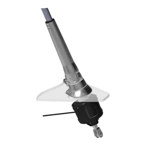
Selden
Selden Furlex 404TD Guide
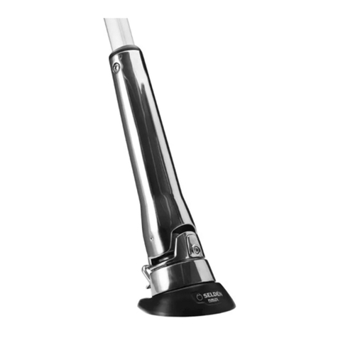
Selden
Selden Furlex 204TD User manual
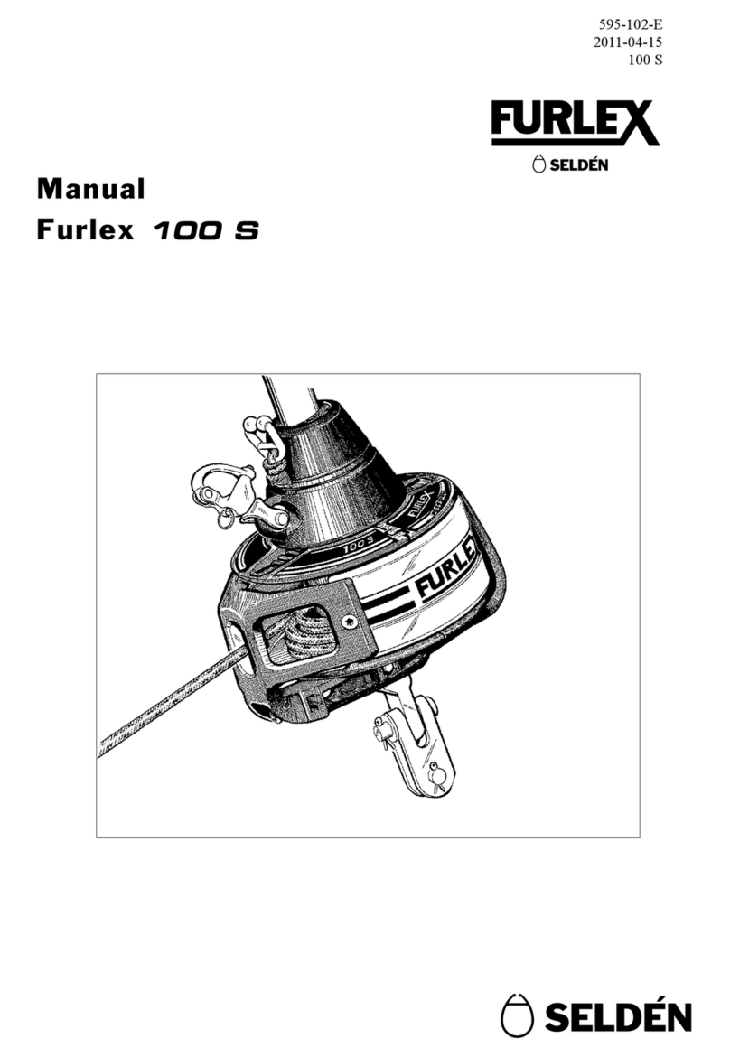
Selden
Selden Furlex 100 S User manual
Selden
Selden Furlex 200 S User manual
Selden
Selden Furlex 200 TD User manual
Selden
Selden Furlex 400 S Supplement
Selden
Selden Furlex 404S Guide
Selden
Selden Furlex 204S Guide
Selden
Selden Furlex 104S Guide

Selden
Selden Furlex 200 S User manual
