Select Medical OLA 8 User manual

User Manual
Dynamic Pressure Redistribution Mattress
& Mattress Overlay

USER MANUAL - OLA 8 & 4
TABLE OF CONTENTS
Statements and Symbols.......................................
Important Noce...................................................
Introducon...........................................................
Contact Informaon..............................................
Product Overview..................................................
Safety.....................................................................
Symbols & Denions............................................
Control Unit & Maress Parts................................
Installaon.............................................................
Operaon...............................................................
Cleaning & Decontaminaon................................
Storage..................................................................
Troubleshoong.....................................................
Maintenance..........................................................
Specicaons.........................................................
Electromagnec Compability..............................
Warranty and Service............................................
2
2
2
2
3
4
6
8
10
12
16
18
20
21
23
24
29
1

Thank you for choosing the OLA 8 or OLA 4 pressure redistribuon
system. This manual should be read carefully before using the maress
as it contains important safety and maintenance informaon to ensure
long lasng and reliable service.
INTRODUCTION
IMPORTANT NOTICE
STATEMENTS AND SYMBOLS
Before operang this medical equipment, it is important to read this
manual and understand the operang instrucons and safety
precauons. If you have any quesons regarding the use of this
equipment please contact your supplier.
Refer to manual
NB: Tips or informaon users should be aware of
Warning to highlight potenal hazards that, if disregarded, could lead to
injury or death.
CONTACT INFORMATION
For any service, warranty, sales or customer service informaon on this
product please contact your supplier or if in doubt contact Select Medical Ltd.
at the following address:
Select Medical Ltd, Unit 10 Philips Rd, Whitebirk Ind Estate, Blackburn,
BB1 5NA.
Customer Service: +44 (0)1254 685535 Sales: +44 (0)1254 668899
Email: info@selectmedical.co.uk
www.selectmedical.co.uk
PRODUCT OVERVIEW
Environment
Your dynamic maress system is intended for use in the following
environments:
• A care environment where medical supervision and monitoring are
provided (e.g. nursing homes, care home, rehabilitaon facilies etc).
• A domesc environment where the maress is used to alleviate or
compensate for an injury or disability.
Intended Use
OLA 8 is an 8” replacement, dynamic pressure redistribuon system
suitable for individuals up to very high risk of developing a pressure ulcer or
for those with exisng ssue damage.
OLA 4 is a 4” pressure relieving overlay suitable for individuals up to high risk
of developing a pressure ulcer or for those with exisng ssue damage.
OLA 8 & 4 provide regular periods of pressure reducon to vulnerable ssue
areas, aiding blood and lymphac ow which is vital to maintaining healthy
ssue. The maress system is designed to be used on standard or proling
beds.
For assistance in seng up, using or maintaining your dynamic maress
system, or to report unexpected operaon refer to the contact details found
on page 2.
Features
OLA 8 & 4 Maress:
• One in two cell-cycle design giving opmum therapy
• Mul-stretch, waterproof and vapour permeable cover
• CPR pull cord for rapid deaon
• Machine washable up to 95°C
• 1 year warranty
Cauon to highlight potenal hazards that if disregarded could lead to
equipment damage or failure.
2 3

OLA 8 Control Unit (Q2-02):
• Audible low pressure alert
• Pressure adjustment for opmum therapy
• External, easy replacement pump lters
OLA 4 Control Unit (D30):
• Low pressure alert
• Pressure adjustment for opmum therapy
• External, easy replacement pump lters
• The maress system & control unit must be installed and used
in accordance with the informaon provided in this manual.
• The maress system is typically not suitable for children. If it is
to be used by a child ensure a risk assessment has been
undertaken.
• Before using the system ensure that the mains lead is free from
damage and is posioned so as not to cause an obstrucon or
trip hazard.
• Exposure of the control unit to any liquid while it is plugged in
could cause a severe electrical hazard.
• Use care when handling or transporng the control unit.
Dropping or other sudden impacts may result in damage to the
unit.
• Do not open the control unit or aempt to repair or service
the unit. Repairs and servicing should always be undertaken by
suitably trained personnel.
• If the control unit is not funconing properly, or has been
damaged, unplug the unit and take it out of service
immediately.
• Do not use the system near a heat source or naked ame.
• Do not use with hot water boles or electric blankets.
• Do not use liquids near the control unit if plugged in.
• Do not place any objects, such as blankets, on or over the
control unit.
SAFETY
General Safety
• Do not use the control unit near ammable gas or in oxygen rich
environments as this poses a re risk or risk of explosion.
• Always assess the risk of intenonal or unintenonal tampering
of the control unit.
Risk Assessment
It is the responsibility of the carer/care provider to carry out the necessary
risk assessment to ensure the safety of the paent. This should be carried out
before using the maress system.
A risk assessment should include, but is not limited to:
• Product combinaons (bed frame, maress, side rails etc.)
• Extent of ssue damage (if any)
• Entrapment
• Paent falls
• Small adults (and children)
• Paents with learning dicules
• Unauthorised people with access to the controls
Contraindicators
Paent condions for which the applicaon of pressure relief on an
alternang maress system is a contraindicaon are as follows:
• Cervical or skeletal tracon
• Unstable spinal fractures
Other contraindicaons may be relevant which are specic to the paent or
care environment.
Maress Load
4 5
OLA 8 OLA 4
Minimum Weight Limit 32kg (5 stone) 32kg (5 stone)
Maximum Weight Limit 190kg (30 stone) 114kg (18 stone)

SYMBOL DEFINITIONS: CONTROL UNIT & MATTRESS
Control Unit
Warning: beware of potenal hazard
Refer to manual: failure to do so could introduce a hazard
Type BF Applied Part
Applied Part: The parts of the device that come into physical
contact with the user/occupant in order for it to carry out its
intended funcon.
Type BF: Applied parts which are electrically isolated from earth
and other parts of the medical equipment - Complying with
specic requirements for protecon against electric shock to
IEC 60601-1
W.E.E.E Label
(Waste Electrical and Electronic Equipment)
Class II electrical device
The user/occupant is protected by at least two layers of insulaon
between the current carrying parts (e.g. mains cable) – If damage
is noced to the control unit or mains cable assembly turn o at
the mains supply and contact your provider or Select Medical Ltd.
immediately.
IP21 Protected from touch by ngers and objects greater than 12
millimeters. Protected from condensaon.
The following symbols are found on the control unit:
6 7
The following symbols are found on the maress:
Disinfect by wiping the surface using a hypochlorite soluon diluted
1000ppm
95 Machine wash up to 95°C
Tumble dry on a low seng
Do not use harsh abrasives or Phenol cleaners
Do not iron
Ensure system is dry before storing
Do not place heavy objects on surface of cover other than the
paent
Do not use when damp, ensure surface is dry before use
Do not fold. Roll pack the system
Do not use sharp objects
Only use in conjuncon with appropriate medical advice
Maress

CONTROL UNIT/MATTRESS PARTS
Control Unit
Maress
1. Top Cover
2. Air Cells
3. Male Air Connector
4. Base Cover
5. Securing Straps (elascated corner straps only on OLA 4)
6. CPR Pull Cord
89
OLA 8 - Q2-02 Control Unit OLA 4 - D30 Control Unit
1. Control Panel
2. On/O switch
3. Mains Power Cable
4. Female Air Connector Port
5. Air Filter
6. Fuse Holders
7. Cushion Bar
8. Hooks
1. Control Panel
2. On/O switch
3. Mains Power Cable
4. Female Air Connector Port
5. Air Filter
6. Cushion Bar
7. Hooks

1. Carefully open the packaging.
2. Although unlikely, please check the product for any signs of damage. Do
not use if damaged and contact your provider or Select Medical Ltd (see
page 2).
3. Place the maress on top of the bed frame (OLA 8), or on top of the
exisng maress (OLA 4), with the top cover facing upwards and the air
hose at the foot end of the bed.
4. Aach the maress to the bed frame by securing with the adjustable
straps. Addionally, OLA 4 has elascated corner straps to tuck under the
exisng maress.
5. Check the CPR pull-cord is securely in posion.
6. Using the hooks on the back of the control unit, hang the unit over the
frame/board at the foot end of the bed. If there is no foot frame/board
lay the unit on the oor, under the bed with the front control panel facing
upwards.
7. Aach the male air connector on the maress to the female air
connector port on the control unit/pump, ensuring the air hose is not
kinked or trapped between parts of the bed frame/other equipment.
8. Plug the mains cable into a suitable mains supply and switch on the
control unit. At this stage both the mains power and low pressure
indicators will illuminate.
9. The maress will start to inate and will be completely inated within
30 - 40 minutes.
10. Once fully inated, adjust the straps that aach the maress to the bed
frame, ensuring the maress is held in place securely.
11. Cover the maress loosely with a sheet, ensuring it does not interfere
with cell alternaon.
10 11
INSTALLATION
Before installing the maress system please read the warning and
cauon notes carefully. These highlight risk areas to ensure paent
safety.
• Ensure the maress is only used with compable equipment/
accessories.
• Ensure the maress is of the correct type for the paent.
• Ensure the CPR pull-cord is easily accessible at all mes.
• Ensure the plug is accessible at all mes so the maress can be
disconnected from the mains supply quickly, if required.
• Ensure the mains cable is plugged into an appropriate power
source at all mes.
• Ensure the mains cable is not taut, parcularly if being used on
a proling bed that moves up and down (check all posions).
• Ensure that the mains cable does not become compressed,
trapped or damaged by the bed frame or other equipment.
• Replace any damaged cable immediately as these cables can
create a risk of electrocuon and/or re.
• A CE marked extension cable must only be used when it is not
possible to reach a wall socket with the equipment mains cable.
• If an extension cable is used never overload it by plugging in
appliances that together will exceed the maximum current
rang stated for the extension cable.
• Do not use block adaptors.
• Ensure extension cables or sockets are not placed under the
bed frame as liquids could leak onto them posing an electrical/
re risk.
• Ensure the mains supply is compable with the control unit
(see page 23 for electrical specicaon)
• Avoid placing the maress system in direct sunlight as this
could damage the maress cover.
• On proling beds it is essenal that adjustable straps are
secured around the movable secons of the bed frame,
otherwise the maress may be damaged.
• If you are placing the control unit on the oor it is advisable to
place the unit on a rm surface.
• Ensure the mains cable is posioned so as not to cause a trip
hazard.
12 13
Maress Operaon
1. Turn on the power on the control unit. The pump starts to inate the
maress to the pressure selected on the dial.
2. The low pressure indicator (orange) will illuminate as inaon commences.
3. OLA 8 /Q2-02 only - the audible alert is acvated, press the ‘alert mute’
buon to mute the alarm and its indicator will ash.
OPERATION
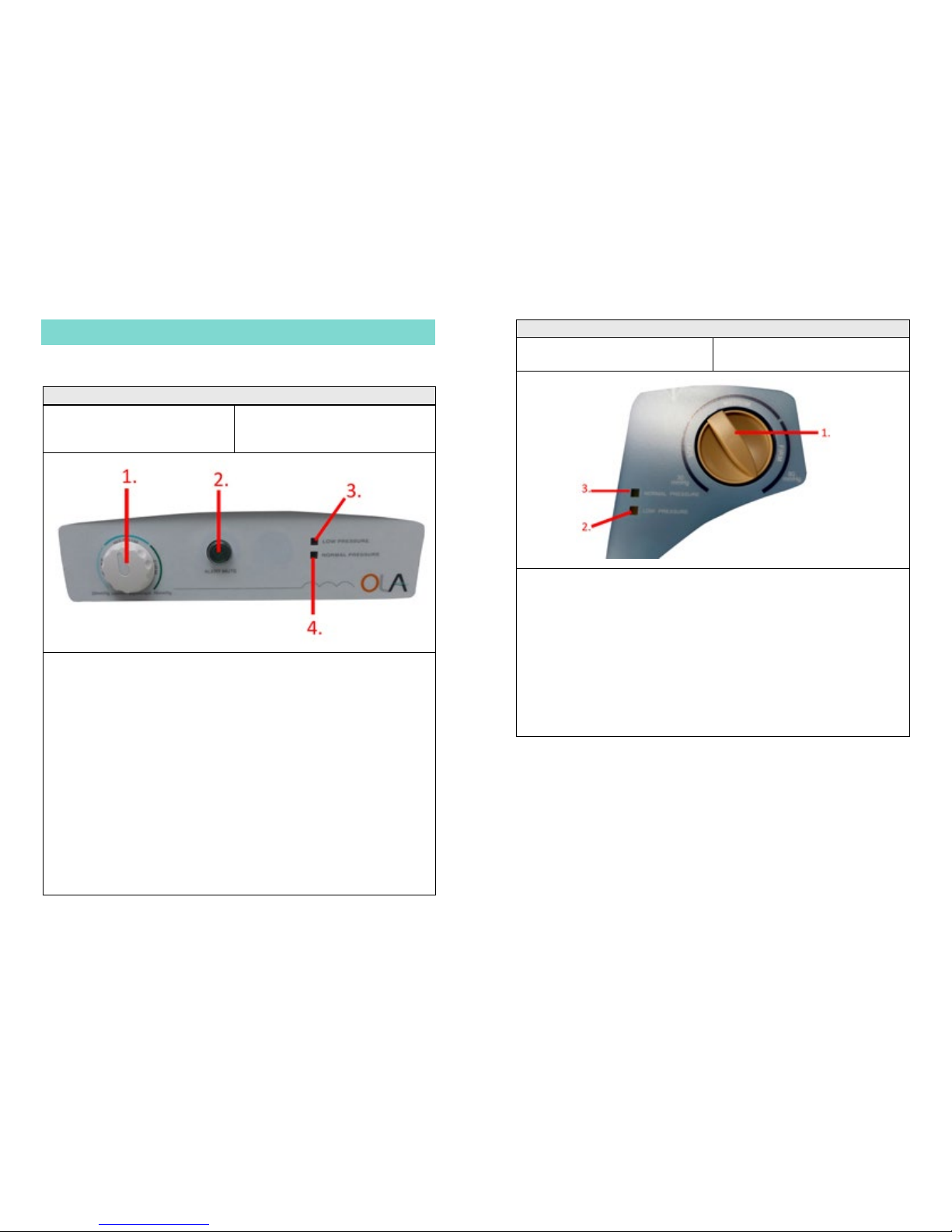
Control Panel
OLA 8 - Q2-02 Control Unit
1. Pressure Adjustment Dial
2. Alert Mute/Reset
3. Low Pressure Indicator
4. Normal Pressure Indicator
1. Pressure Adjustment Dial
Turn the dial to set the system for opmum performance.
2. Alert Mute/Reset
The audible/visual alarm idenes when the pressure is low. To mute the
audible alarm press the buon. The visible alarm indicator will now ash.
Re-press the buon to reset the alarm.
3. Low Pressure Indicator
A visible indicator (orange) warns that the pressure is below an acceptable
level.
4. Normal Pressure Indicator
A visible indicator (green) idenes that the pressure has reached the
preset level.
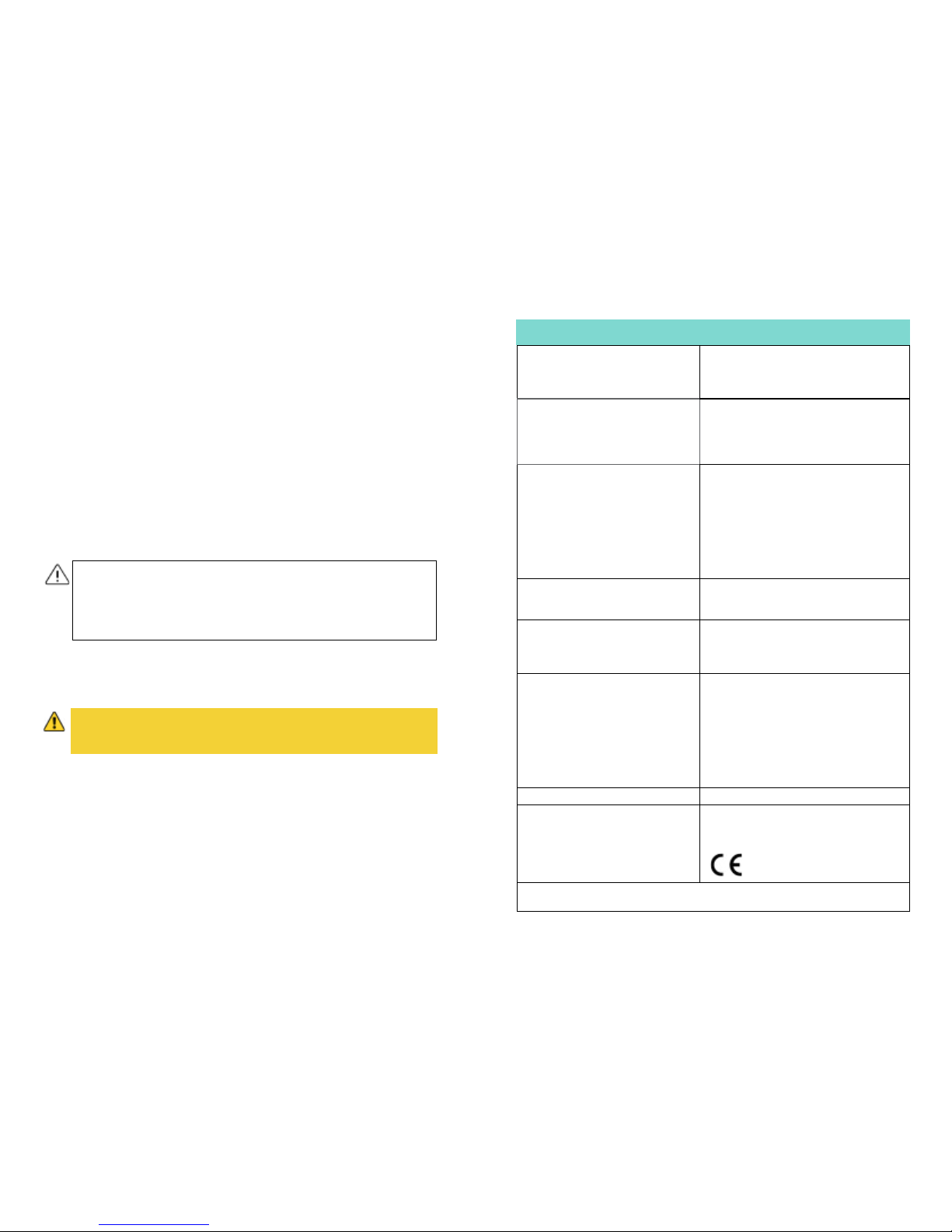
OLA 4 - D30 Control Unit
1. Pressure Adjustment Dial
2. Low Pressure Indicator
3.Normal Pressure Indicator
1. Pressure Adjustment Dial
Turn the dial to set the system for opmum performance.
2. Low Pressure Indicator
A visible indicator (orange) warns that the pressure is below an acceptable
level.
3. Normal Pressure Indicator
A visible indicator (green) idenes that the pressure has reached the
preset level.

14 15
4. Once opmum pressure is reached (about 30-40 minutes) the ‘normal
pressure’ indicator will come on and the ‘low pressure’ indicator (and audible
alarm on the OLA 8/Q2-02 ) will turn o.
NB: If the ‘low pressure’ indicator (audible alarm) will not go o, refer to
troubleshoong on page 20.
5. Adjust the ‘pressure/comfort control’ dial to provide a comfortable
pressure level for the paent. Pressure range:
• OLA 4 / D30: 30-80mmHg
• OLA 8 / Q2-02: 20-60mmHg
NB: Hand check - to check if the pressure is adequately supporng the
paent, slide one hand between the air maress and the bed frame under
the paent’s boom. You should be able to slide the hand in-between and
the opmum range is 25 - 40mm (1” to 1.5”).
6. Using clinical judgement and with connuous monitoring of the paent
for up to 72 hours, increase or decrease the pressure levels using the dial to
suit the paents comfort levels. If possible, having regular dialogue with the
paent is key.
NB: The maress can be used in an upright posion, however the pressure
seng may need to be increased. Use clinical judgement to ensure paent
comfort and eecve pressure relief is maintained.
CPR Funcon
In an emergency rapid deaon of the maress may be required. The CPR
pull cord is located at the head end of the maress.
Using Inconnence Products with the Maress
Inconnence products, such as sheets or pads, can be used with the system,
however this may compromise the eecveness of the alternang pressure
distribuon.
Transporng the Maress & Power Cuts
If the maress is disconnected from the power supply so it can be moved, or
in the event of a mains power failure, carry out the following procedure to
maintain maress inaon:
1. Disconnect the male connector from the power unit by squeezing the two
tabs (A) and pulling away from the control unit (B).
To re-inate push the CPR cord back into the closed posion. The maress
will start to inate. Wait for opmal pressure to be reached before using the
maress.
2. Seal using the cap marked “Transport” which for safety is aached to the
male connector.
NB: Complete the acon quickly to limit air
loss.
3. Switch o the control unit.
4. Disconnect from the power supply.
5. The maress can now be moved.
• Carers/care providers should always familiarise themselves with
the posion of the CPR valve.
• If inconnence products are being used it is important to carry
out a risk assessment and regular paent skin checks.

Maress
N.B: Before aempng to clean the maress the top cover should be checked
for physical signs of damage that may lead to strike-through (ingress of uid
through cover). Staining to the underside of the top cover is a sign of
strike-through.
16 17
CLEANING & DECONTAMINATION
Cleaning
Cleaning is required regularly between paents to prevent cross infecon. It is
therefore important to clean and decontaminate the control unit and
maress following these procedures.
Control Unit
1. Check for external damage – do not use if damage is found.
2. Place the pump on a work surface and using a clean cloth wipe the outside
of the case with a prepared sodium hypochlorite soluon (1000ppm).
3. The control unit should be cleaned by starng with the cleanest parts and
systemacally moving to the direst parts. Extra care should be taken around
areas where excess dirt or dust may gather.
4. Change the cloth if it becomes dirty.
5. Once clean, wipe down with a new clean cloth moistened with clean
water to remove detergent residue.
6. Dry o with a paper towel. Always allow the surfaces to dry thoroughly
before pung back into use.
• The maress will remain inated for up to 24 hours - return the
system to the mains supply as soon as possible.
• Whilst unplugged alternang mode will not be operaonal and
pressure relief will not be provided.
• Do not remove the maress from the bed frame if the occupant
is sll on the maress.
• If it is essenal that the paent is moved whilst remaining on the
maress, the maress must be re-plugged in immediately once
the desired locaon has been reached to reduce the risk of ssue
damage.
• Never drag the maress, always carry it.
• Disconnect the mains cable from the power socket before
aempng to clean the control unit.
• Do not immerse or soak the pump.
• Do not spray any cleaning soluon directly on the surface of the
control unit.
• If any of the cleaning/washing instrucons are not followed the
product warranty will be invalidated.
• Do not use phenol based cleaning soluons, solvents, neat
bleach or abrasive products to clean the casing as this may
cause damage.
• Frequent or prolonged exposure to higher concentraon
disinfectant soluons may prematurely age the fabric cover of
the maress.
• Do not use the cover if strike-through or damage is found – risk
of cross infecon. Replace with a new top cover.
• Do not use solvents or alcohol-based cleansers e.g. Phenicol,
Hibiscrub, Clearsol, Stericol or Hycoline as these will destroy the
maress materials.
• Do not autoclave.

18 19
Decontaminaon
1. Unzip the top cover from the maress.
2. The top cover/base cover can be machine washed up to 95°C and tumble
dried on a cool seng.
3. Unsnap the air cells from the maress base on both sides.
4. Carefully clean with (1000ppm) prepared soluon of sodium hypochlorite
and allow to dry completely.
5. Make sure to disconnect all the air cells and spray the cleaning soluon on
all sides, including the connecng tubes and hoses.
6. Re-assemble the maress and lay it out at.
7. Ensure the maress is completely dry before either storing or using for
another paent.
STORAGE
Environmental Condions
The following condions should be followed when storing the maress
system:
• Ambient temperature: -25°C to +70°C
• Humidity: < 93% max, non-condensing
General Cleaning:
1. Wipe down with a clean cloth moistened with a mild detergent and diluted
in warm water (40˚C).
2. Rinse with cold clean water and a clean cloth and allow to fully dry before
use.
• The maress system must be decontaminated prior to any
storage to avoid risk of cross contaminaon.
• Do not fold, crease or stack maresses.
• Do not stack control units.
• Do not store whilst inated.
Storage
1. Detach the control unit from the maress.
2. Pull the CPR cord unl it is open.
3. Ensure there is no air trapped in the cells.
4. Lay the maress out at and roll the maress from the foot end towards
the head end.
5. Store in a sealed polythene bag to protect from dirt, debris, uids etc. with
a suitable idencaon tag.
6. Store the control unit in a separate, sealed polythene bag to protect from
dirt, debris, uids etc. with a suitable idencaon tag.

20
MAINTENANCE
General Maintenance
Select Medical recommend that frequent visual and operaonal
inspecons are undertaken. Clean the air lter, found at the back of the
control unit, once a month with mild detegent. If there are any signs of
damage, or the system is not performing as it should, withdraw it from
service unl the system has been repaired and is t for use again.
Yearly Maintenance
• Check the air lter is in good condion and replace or clean as required.
• Check that all electrical funcons operate correctly on the control unit.
• Check that all audible and visual indicators work appropriately (when
plugged in and unplugged from mains supply).
• Check that the baery is sll funconal and operates in the event of a
power loss.
• Check that the maress reaches the required pressures.
• Check the CPR connecon on the maress.
• Check the cover for tears, punctures, abrasion marks and split seams.
21
TROUBLESHOOTING
Problem Acons
Power Failure 1. Turn o the control unit to silence the alarm and unplug from
the mains supply (NB: the mute buon on OLA 8, Q2-02 does not
silence the power failure indicaon).
2. Check the mains socket is working - plug in a device that is
known to work.
3. Plug the control unit back into the wall socket.
4. Turn on the control unit. If control unit sll fails to operate:
5. Turn o the control unit at the wall & replace plug fuse.
6. Turn on the control unit. If control unit sll fails to operate:
7. Replace control unit fuses – See page 23 for fuse types.
8. Turn on the control unit. If control unit sll fails to operate, turn
o at the mains and contact your approved service provider.
Incomplete
inaon/low
pressure
1. Ensure the maress air connector is properly connected to the
control unit, is not constricted in any way and has no kinks.
2. Ensure the CPR pull-cord is rmly in place and no air is leaking.
3. Turn the unit o and then on again to clear the indicator.
If the ‘low pressure’ indicator connues to illuminate:
4. Remove the top cover and ensure there is no air leakage within
the maress – cells, tubing and connectors.
5. Turn the unit o and then on again to clear the indicator.
If a low pressure indicator is sll evident turn o at the mains and
contact your approved service provider
Alternang
mode failure
1. Turn o the control unit.
2. Disconnect the male air connector to reduce cell pressure.
3. Reconnect air connector.
4. Turn on the control unit.
5. If alternang mode is sll inoperable turn o at the mains and
contact your approved service provider.
Paent is
booming out.
1. Ensure the paent is suited to the rang of the maress.
2. Ensure the paent is centrally posioned on the maress.
3. Increase the pressure seng – Refer to ‘Maress Operaon’
pg 13-14
• DO NOT open the control unit - risk of electrocuon
• If mains plug, cable or outer casing is visibly damaged turn o at
the mains and contact your approved service engineer.
• Always disconnect the control unit from the mains power supply
prior to performing any maintenance procedures (when viable).
• No modicaon of this equipment is allowed.
• The maress system should be vacated by the paent before any
maintenance or inspecon takes place. If this is not possible due
to the paent’s mobility, care should be taken for the service
engineer not to make contact with the paent when working on
electrical items.
• Only Select Medical approved components specied for OLA 8 &
4 are to be used - if in doubt contact Select Medical Ltd or your
local distributor.
• Only authorised service personnel or Select Medical service
engineers should carry out repairs or service acvies. Failure
to do so may result in the product warranty becoming void.
• The maress system should be serviced once a year, as a
minimum.
Classicaon: Electrical shock protecon: Class II, Type BF
Applied Part: Maress
Liquid ingress protecon: IP21
Not AP or APG equipment*
Supply Rang:
Fuse Rang:
Mains Plug:
230V, 50Hz, 12W
Mains Plug – 5A
Q2-02 Control Unit - T1A, 250VAC
D30 Control Unit - T1A, 250VAC (internal)
Type G/BS1363
Maress Dimensions (inated):
Maximum Paent Weight:
No. of cells:
Alternang Therapy:
Cycle Time:
Pressure Range:
OLA 8: 2000mm x 900mm x 200mm
OLA 4: 1850mm x 900mm x 102mm
OLA 8: 190kg (30 stone)
OLA 4: 114kg (18 stone)
OLA 8: 20 OLA 4: 17
AB paern
12 minutes
OLA 8 / Q2-02: 20-60mmHg
OLA 4 / D30: 30-80mmHg
Control Unit Dimensions:
Control Unit Weight:
OLA 8: (L) 206mm x (W) 280mm x (D) 104mm
OLA 4: (L) 260mm x (W) 140mm x (D) 100mm
OLA 8: 2.6kg OLA 4: 2.4kg
Cover Material:
Cell Material:
Base Material:
Polyurethane coated mul-stretch nylon
Nylon/PVC
OLA 8: Nylon/PU
OLA 4: PVC mesh
Transport and Storage Condions:
Operaonal Condions:
Atmospheric Pressure:
Operang Altude:
Polluon:
UV:
Noise level:
Ambient Temp: -25°C to +70°C
Humidity: < 93%, non-condensing
Ambient Temp: +5°C to +40°C
Humidity 15% - 93%, non-condensing
700hPa to 1060hPa
≤ 2000m
Degree 2
Intended for indoor use only
<40dB(A)
Warranty: 1 year
Safety Standards: IEC 60601-1: 2005
IEC 60601-1-2:2007
IEC 60601-1-11:2010
* Not suitable for use in the presence of ammable anaesthec mixtures with air, oxygen or
nitrous oxide.
SPECIFICATION
22 23
The control unit is tested and CE
marked in line with Medical Device
Direcve 93/42/EEC
• Check for signs of of strike-through (uid ingress) to the underside of the
cover.
• Check that all piping and cells within the maress are in good condion
and that there is no kinking evident.
• Check the control unit housing is not cracked or damaged, if damaged the
control unit must be removed from operaon immediately.
• Check that the mains cable and plug are in good condion, if either is
damaged it must be replaced with a complete assembly, the plug must
never be re-wired.
Disposing of Parts
When the electrical system has come to the end of its useful life, contact your
provider or Select Medical Ltd. (see pg 2) to arrange for collecon,
alternavely follow local recycling and W.E.E.E. (Waste Electrical and
Electronic Equipment) policies.
The metal and plasc components used in both the maress and control unit
are also to be separated and disposed of following local recycling policy as
these can also be recovered and reused/recycled.
• The control unit should not be disposed of in general municipal
waste. Some of the electrical components could be harmful
to the environment and where viable the components can be
recovered and reused/recycled.
• The maress system is to be decontaminated before disposal to
avoid risk of cross contaminaon.

Requirements according to IEC 60601-1-2:2007
OLA 8 & 4 are intended for use in the electromagnec environment specied
below.
Guidance and manufacturer’s declaraon –
electromagnec emissions
Emission test Compliance Electromagnec
environment – guidance
RF emission
CISPR 11
Group 1 The control unit uses RF energy only for
its internal funcon. Therefore, its RF
emissions are very low and are not likely
to cause any interference in nearby
electronic equipment.
RF emission
CISPR 11
Class B OLA 8 & 4 are suitable for use in all
establishments, including domesc
establishments and those directly
connected to the public, low-voltage
power supply network that supplies
buildings used for domesc purposes.
Harmonic emissions
IEC 61000-3-2
Class A
Voltage uctuaons/
icker emissions
IEC 61000-3-3
Complies
24 25
ELECTROMAGNETIC COMPATIBILITY
• The control unit should not be used next to or stacked with
other equipment where possible. If this is unavoidable the
control unit should be observed to verify normal operaon.
The control unit has been designed to meet the EMC requirements of IEC
60601-1-2:2007. This standard denes the levels of immunity to
electromagnec interferences as well as maximum levels of electromagnec
emissions for medical devices. They are in place to provide reasonable
protecon against dangerous interference in a medical or residenal
environment.
Immunity to electromagnec interference - this refers to the levels of
electromagnec interference that the control unit can withstand from
nearby sources radiang radio frequency (RF) energy (e.g. from mobile
phones, network devices etc).
Electromagnec emissions - this refers to the levels of RF energy the control
unit emits.
The immunity levels are set out in the following manufacturers guidance. If
these levels are exceeded then the system may not operate correctly or stop
operang. It is important therefore to try to ascertain the source of the
interference by turning nearby equipment o. There are simple measures
that can be taken to correct the problem:
• Remove or relocate the interfering equipment
• Increase the separaon distance between the control unit and the
interfering equipment
The RF emissions are set out in the following manufacturers guidance. The
control unit generates very low RF energy, however interference to sensive
equipment is sll possible. If interference to radio/tv recepon and/or other
equipment is suspected, turning the control unit o and on can determine if
this is the case. There are simple measures that can be taken to correct the
problem:
• Relocate the receiving antenna
• Increase the separaon distance between the control unit and aected
equipment
Due to the increasing number of wireless devices, such as laptops and mobile
phones, it is important that the system is installed following the
manufacturer’s guidance to ensure connued and reliable operaon.

26 27
Guidance and manufacturer’s declaraon –
electromagnec immunity
Immunity test IEC 60601 test
level
Compliance
level
Electromagnec environment –
guidance
Conducted RF
IEC 61000- 4-6
Radiated RF
IEC 61000- 4-3
3 Vrms
150 kHz to 80
MHz
3 V/m
80 MHz to 2.5
GHz
3 Vrms
3 V/m
Portable and mobile RF communicaons
equipment should be used no closer to
any part of the control unit, including
cables, than the recommended separaon
distance calculated from the equaon
applicable to the frequency of the
transmier.
Recommended separaon distance
d = 1.2√P
d = 1.2√P 80 MHz to 800 MHz
d = 2.3√P 800 MHz to 2.5 GHz
Where P is the maximum output power
rang of the transmier in was (W)
according to the transmier manufacturer
and d is the recommended separaon
distance in metres (m). Field strengths
from xed RF transmiers, as determined
by an electromagnec site survey*,
should be less than the compliance level
in each frequency range**.
Interference may occur in the vicinity of
equipment marked with the following
symbol:
N.B: At 80 MHz and 800 MHz, the higher frequency range applies. These guidelines may not
apply in all situaons. Electromagnec propagaon is aected by absorpon and reecon
from structures, objects and people.
* Field strengths from xed transmiers cannot be predicted theorecally with accuracy. To
assess the electromagnec environment due to xed RF transmiers, an electromagnec
site survey should be considered. If the measured eld strength in the locaon in which the
OLA 8 or 4 is used exceeds the applicable RF compliance level above, OLA 8 or 4 should
be observed to verify normal operaon. If abnormal performance is observed, addional
measures may be necessary, such as re-orienteering or relocang the system.
** Over the frequency range 150 kHz to 80 MHz, eld strengths should be less than 3 V/m.
Guidance and manufacturer’s declaraon –
electromagnec immunity
Immunity test IEC 60601 test level Compliance level Electromagnec
environment –
guidance
Electrostac
discharge (ESD)
IEC 61000-4-2
±6 kV contact
±8 kV air
±6 kV contact
±8 kV air
Floors should be
wood, concrete or
ceramic le.
If oors are
covered with
synthec material,
the relave
humidity should be
at least 30%.
Electrical fast
transient/burst
IEC 61000-4-4
±2 kV for power
supply lines
±1 kV dierenal mode
±2 kV common mode
Mains power
quality should be
that of a typical
commercial or
hospital
environment.
Surge
IEC 61000-4-5
± 1 kV line(s) to line(s) ± 1 kV dierenal mode Mains power
quality should be
that of a typical
commercial or
hospital
environment.
Voltage
dips, short
interrupons and
voltage
variaons
on power supply
input lines
IEC 61000-4-11
<5% UT (>95% dip in UT)
for 0.5 cycle
40% UT (60% dip in UT)
for 5 cycles
70% UT (30% dip in UT)
for 25 cycles
<5% UT (>95% dip in UT)
for 5 sec
<5% UT (>95% dip in
UT) for 0.5 cycle
40% UT (60% dip in UT)
for 5 cycles
70% UT (30% dip in UT)
for 25 cycles
<5% UT (>95% dip in
UT) for 5 sec
Mains power
quality should be
that of a typical
commercial or
hospital
environment.
PPower
frequency
(50/60Hz)
magnec eld
IEC 61000-4-8
3A/m 3A/m Power frequency
magnec elds
should be at levels
characterisc of a
typical locaon in a
typical commercial
or hospital
environment.
N.B: UT is the a.c. mains voltage prior to applicaon of the test level.

WARRANTY & SERVICE
28 29
OLA 8 & 4 are intended for use in an electromagnec environment in which
radiated RF disturbances are controlled. The customer/user of OLA 8 or 4 can
help prevent electromagnec interference by maintaining a minimum
distance between portable and mobile RF communicaons equipment
(transmiers) and the OLA 8 & 4 system as recommended below, according to
the maximum output power of the communicaons equipment.
Recommended separaon distances between portable and
mobile RF communicaons equipment and the control unit
Rated maximum output
power of transmier (W)
Separaon distance according to frequency of transmier (m)
Electromagnec environment – guidance
150 KHZ TO 80 MHZ
D = 1.2√P
80 MHZ TO 800 MHZ
D = 1.2√P
800 MHZ TO 2.5
GHZ D = 2.3√P
0.01 0.12 0.12 0.23
0.1 0.38 0.38 0.73
1 1.2 1.2 2.3
10 3.8 3.8 7.3
100 12 12 23
For transmiers rated at a maximum output power not listed above, the recommended
separaon distance d in metres (m) can be esmated using the equaon applicable to the
frequency of the transmier, where P is the maximum output power rang of the transmit-
ter in was (W) according to the transmier manufacturer.
N.B: At 80 MHz and 800 MHz, the separaon distance for the higher frequency range
applies. These guidelines may not apply in all situaons. Electromagnec propagaon is
aected by absorpon and reecon from structures, objects and people.
• Select Medical Ltd guarantees this equipment under normal use for a
period of 1 year aer delivery to the original purchaser, proof of
purchase must be presented with any claim.
• For any equipment returned within the warranty period and proven to be
defecve we agree to either:
a) correct the defect by product repair
b) replace the product with one of the same or similar design or
c) refund the purchase price, without charge.
Repaired or replaced parts and products are warranted for the remainder
of the original warranty period. You will be charged for repair or
replacement of the product made aer the expiraon of the warranty
period.
• This warranty excludes equipment damage or failure through acts of god,
an incidence of excess voltage or current, shipping, tampering, improper
maintenance, carelessness, accidental damage, negligence or misuse,
or products which have been altered, repaired or dismantled other than
with the manufacturer’s wrien authorizaon and by its approved
procedures and by properly qualied technicians.
• In no event shall Select Medical be liable for any direct or indirect
damages or losses resulng from the use of the equipment.

Contact Information
www.selectmedical.co.uk
Registered in England No. 4281283 | VAT Reg No. 785 7314 91
Other manuals for OLA 8
1
This manual suits for next models
1
Table of contents
Other Select Medical Medical Equipment manuals

Popular Medical Equipment manuals by other brands


Getinge
Getinge Arjohuntleigh Nimbus 3 Professional Instructions for use

Mettler Electronics
Mettler Electronics Sonicator 730 Maintenance manual

Pressalit Care
Pressalit Care R1100 Mounting instruction

Denas MS
Denas MS DENAS-T operating manual

bort medical
bort medical ActiveColor quick guide

AccuVein
AccuVein AV400 user manual


