Selkirk SUPERVENT SC Instructions for use

1
SELKIRK CORPORATION
5030 Corporate Exchange Blvd. SE,
Grand Rapids, MI 49512
1.800.992.VENT (8368)
&
SUPERVENT (SC & FC)
SUPERPRO (SPR)
©2021 SuperVent / SuperPro All Rights Reserved 3010122
SELKIRK CANADACORPORATION
950 South Service Road, Second Floor
Stoney Creek, ON L8E 6A5
1.888.SELKIRK(735.5475)
02/12/2021
FACTORY BUILT
INSULATED CHIMNEY
LISTED
A MAJOR CAUSE OF VENT
RELATED FIRES IS FAILURE TO
MAINTAIN REQUIRED
CLEARANCES (AIR SPACES) TO
COMBUSTIBLE MATERIALS.
IT IS OF THE UTMOST
IMPORTANCE THAT THIS
CHIMNEY SYSTEM BE
INSTALLED ONLY IN
ACCORDANCE WITH THESE
INSTRUCTIONS.
PLEASE READ ALL INSTRUCTIONS
BEFORE BEGINNING YOUR
INSTALLATION.
FAILURE TO INSTALL THIS SYSTEM IN
ACCORDANCE WITH THESE
INSTRUCTIONS WILL VOID THE
CONDITIONS OF CERTIFICATION AND
THE MANUFACTURER'S WARRANTY.
Installer: It is of the utmost importance that
these instructions are left with the homeowner.
Homeowner: Keep these instructions and
maintenance guide in a safe place for future
reference.
Tested to
UL 103 Type HT
and
CAN/ULC-S604
INSTALLATION I NSTRUCTIONS
&
MAINTENANCE G UIDE
(CANADA & UNITED STATES)

2
3
4
4, 5
5
5
5, 6
6
6, 7
7, 8
8, 9
9
9, 10, 11
11
11 - 15
15, 16
16, 17
17
17
17, 18
18, 19
20
21
22
22
23
24
TABLE OF CONTENTS
CERTIFICATION LABELS
TYPE OF APPLIANCES
PRE INSTALLATION GUIDELINES
TOOLS
FRAMING DETAILS
CEILING SUPPORT INSTALLATION
STOVE PIPE ADAPTOR
ADJUSTABLE LENGTH
ATTIC INSULATION SHIELD INSTALLATION
FIRESTOP RADIATION SHIELD INSTALLATION
ELBOW INSTALLATION
WALL SUPPORT INSTALLATION (AWS)
INTERMEDIATE WALL SUPPORT (AIWS)
WALL SUPPORT INSTALLATION (WS)
WALL BANDS
CATHEDRAL CEILING SUPPORT INSTALLATION
RAFTER RADIATION SHIELD INSTALLATION
ROOF SUPPORT INSTALLATION
ROOF FLASHING INSTALLATION
ROOF GUY INSTALLATION
MAINTENANCE AND CLEANING OF CHIMNEY
CHART 1 - OFFSET CHIMNEY INSTALLATION
CHART 2 - CHIMNEY HEIGHT ABOVE THE ROOF
CHART 3 - CONNECTOR PIPE CLEARANCES - CATHEDRAL SUPPORT
REPLACEMENT PARTS LIST
INSTALLATION RECORD

3
SELKIRKCANADACORPORATION
09/29/20
09/29/20
CERTIFICATIONLABELS

4
PRE-INSTALLATION GUIDELINES
Beforebeginningthe installation ensurethatyou obtain anynecessary
buildingpermits, andthatyourinstallationwillconformwith allfederal
and municipal building code requirements.
WARNING: DO NOT PLACE ANY INSULATING MATERIALS OR
RUN ANY ELECTRICAL WIRING WITHIN THE REQUIRED AIR
CLEARANCE SPACE SURROUNDING THE CHIMNEY.
Ifthechimneymust be installedonanexterior wall itisrecommended
that the chimney be enclosed below the roof line to protect the
chimney from cold outdoor temperatures, this may help reduce
condensation, creosote formation and enhance draft. Ensure extra
space is provided for an access door by the Insulated Tee for chimney
inspection and cleaning. The exterior enclosure may be insulated,
maintainingtherequiredminimumair spaceclearanceof 2" toanypart
of the chimney. Consult local building codes for cold climate
application.
TYPE OF APPLIANCES
If you choose to have your product professionally installed, we
recommend these products be installed by professionals who are
certified in the U. S. by NFI (National Fireplace Institute).
Your SuperVent/SuperProchimneyandconnectingstovepipediameter
should be sized in accordance with the appliance manufacturer’s
recommendations.
Plantheinstallationofyour appliance and chimney insuchawaythat
both your chimney and your stove pipe run is as short and straight
aspossible. Byhavingtoo long andormultiplebendinstallations you
can reduce system draft which can affect the operation, and or
performance of your appliance and or chimney system. The chimney
shouldbelocatedwithinthebuildingsoasto avoid cutting or altering
load bearing members such as joists, rafters, studs, etc. If you require
to cut or alter an existing load bearing member, special reframing
methods are required which often include doubling of adjacent
members. If such a case arises, contact your local Building Code
Official regarding local regulations and proper installation methods.
Sections of the SuperVent/SuperPro chimney which pass through
accessible areas of the building such as through closets, storage areas,
occupied spaces or any place where the surface of the chimney could
be contacted by persons or combustible materials must be enclosed
in a chase to avoid personal contact and damage to the chimney. The
chase may be fabricated using standard building materials. Drywall
CANADA APPLICATIONS
In Canada, Model SuperVent/SuperPro is intended for connection to
liquidfuelor gasfiredresidentialtype appliancesandbuildingheating
appliances, in which the maximum continuous flue gas temperatures
donotexceed540ºC(1000°F)asperULC-S604. It hasbeentestedand
approvedtowithstandtemperaturesofupto925°Cforthree30minutes
intervals.
May also be used with specific factory-built fireplaces listed to
UL 127 and CAN/ULC-S610 when specified in the fireplace
manufacturer's installation instructions.
Thefluediameter ofgasor oilappliancesshould complywithNational
and Provincial Building Code of Canada and appropriate Installation
Codes;CAN/CSA-B149forgasandCAN/CSA-B139 foroil.
mounted on 2” x 4” studs is typically used in this situation. The space
betweentheouter wallofthe chimneyandtheenclosure mustbea least
aminimumof2inches.
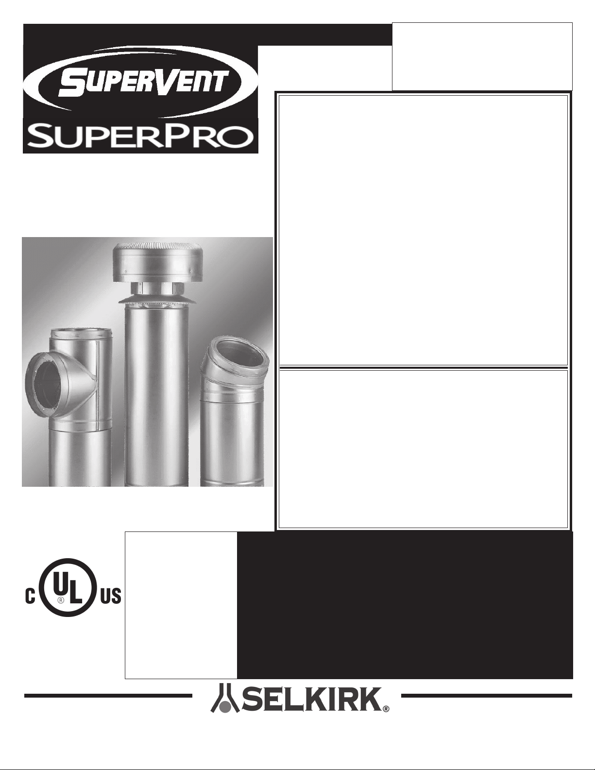
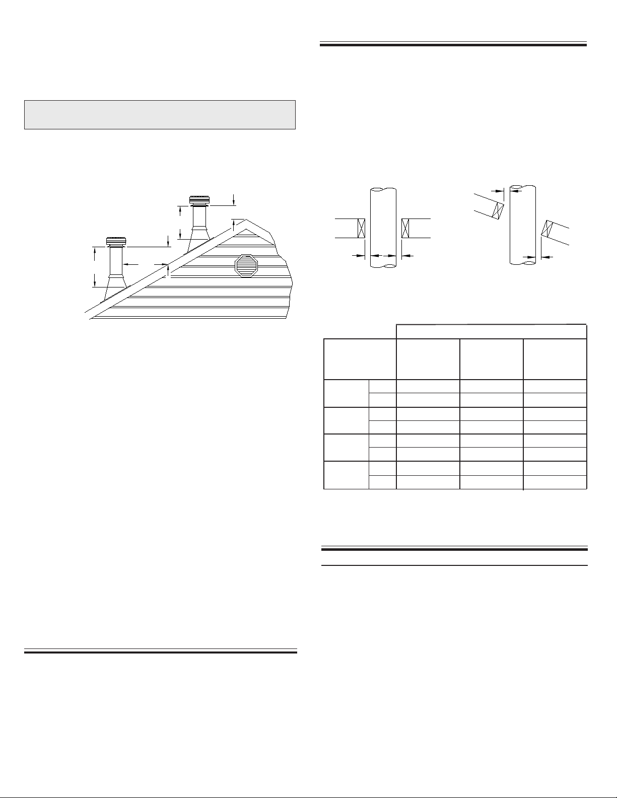
MAINTAIN A 2" MINIMUM AIR SPACE CLEARANCE
BETWEEN INSULATED CHIMNEY SECTIONS AND COMBUSTIBLE
MATERIALS OR AS ESTABLISHED BY SUPPORT ASSEMBLY.
CONTACT LOCAL BUILDING OR FIRE OFFICIALS
ABOUT RESTRICTIONS AND INSTALLATION
INSPECTION IN YOUR AREA.
U.S.A. APPLICATIONS
IntheU.S.A.,Model SuperVent/SuperPro has beentestedperUL103
as a "Type HT" chimney by Underwriters Laboratories, Inc. As such
it is code approved for connection to solid, liquid or gas fueled
appliances in which the maximum continuous flue gas temperatures
do not exceed 1000°F. It has been tested and approved to withstand
temperatures of up to 2100°F for three ten minutes intervals.
Factory built chimneys are intended for installation in accordance
with NFPA 211 (Standard for Chimneys, Fireplaces, Vents and Solid
Fuel Fired Appliances), and/or local and regional codes such as the
International Mechanical Code and Uniform Mechanical Code, etc.
The flue diameter of gas or oil fired appliances should comply
with the appropriate NFPA or ANSI Installation Codes; NFPA 54,
ANSIZ223.1,andNFPA 31.
This chimney system is suitable for venting gas, oil or solid fuel fired
appliances including wood stoves, furnaces, boilers and fireplaces.
TheNationalFireProtectionAssociation Standard211states:Factory-
built chimneys that pass through floors of buildings requiring the
protection of vertical opening shall be enclosed with approved walls
having a fire resistance rating of not less than 1 hour where such
chimneys are located in a building less than four stories in height, and
not less than 2 hours where such chimneys are located in a building
four or more stories in height.
YOUR CHIMNEY HAS BEEN TESTED, AND LISTED USING ALL
OF THE SUPPORTS, SHIELDS, ETC., DESCRIBED HEREIN.
DELETION OR MODIFICATION OR ANY OF THE REQUIRED
PARTS OR MATERIALS MAY SERIOUSLY IMPAIR THE SAFETY
OF YOUR INSTALLATION,AND VOID THE CERTIFICATION AND
OR WARRANTY OF THIS CHIMNEY
AnAtticInsulation Shieldmustbeinstalled where thechimneypasses
into an attic space. It is designed to keep insulation materials or debris
from coming into contact with the chimney. It must accomodate the
amount of insulation as required by the National Building Code.
Whereheightrestrictions willnotpermitthe useoftheAttic Insulation
Shield, it is permissible to construct an enclosure with a 2” air space
clearancetothe outer pipealltheway totheundersideof theroofdeck.
In this application you need to install a Firestop Radiation Shield on
the ceiling side and a Rafter Radiation Shield at the roof level.
At the level where the chimney penetrates the air/vapour barrier,
special attention is required. Seal the vapour barrier to the Firestop
Spacer or Ceiling Support assembly or Wall Thimble using an appro-
priate caulking compound as per the requirement of local authorities.
Theideallocation foryourchimney iswithinthebuildingenvelope. In
cold climates, the use of external chimneys may result in operational
problems such as poor draft, excessive condensation of combustion
products and rapid accumulation of creosote. Under these circum-
stances, the installation of the chimney within the building is strongly
recommended.

5
2" Min.
2" Min.
2" Min.
2" Min.
mm
mm
mm
mm
11 x 11
280 x 280
13 x 13
330 x 330
14 x 14
123/8x 123/8
315 x 315
143/8x 143/8
365 x 365
133/8x 133/8143/8x 143/8
340 x 340 365 x 365
143/8x 143/8
365 x 365 355 x 355365 x 365
143/8x 143/8
12 x 12
305 x 305
123/8x 123/8
315 x 315
143/8x 143/8
365 x 365
6
(125mm)
7
(175mm)
8
(200mm)
5
(150mm)
Authorities require that the chimney extend not less than 3 feet above
the highest point where it passes through the roof of a building and
notlessthan 2feetaboveany portionofthebuilding within10feet(see
figure1). SeeChart2forChimneyHeightAbovethe Roof on page 21
of these instructions.
The use of Locking Bands at all chimney joints is recommended for
added safety and stability when exposed to high winds and as a
precaution against accidental unlocking of lengths when the system
is inspected and swept.
Obtain any necessary building permits.
Do not install the chimney directly at the outlet of the appliance.
Interconnecting stove pipe is required unless the appliance is
specifically approved for this type of installation.
Use only with an appliance listed by a recognized testing authority
such as Underwriters Laboratories Inc., Underwriters laboratories of
Canada, or Intertek Testing Services.
WEARSAFETYGLOVES WHENHANDLING
SHEETMETAL PARTSWITH SHARPEDGES
FIGURE1
3ft.
min.
2ft.
3ft.
min.
2ft.
10ft.
Do not mix and match with other manufacturer's products. Use only
Selkirk's Models JSC/SPR/JFC listed components.
CHIMNEYSIZING:
In order to achieve safe, optimum performance of the appliance,
servicelifeof the chimney,thechimney must besizedcorrectly for the
connectedappliance. Ingeneral,thechimney flue should bethesame
size as the appliance flue outlet. The installation should be done in
accordance with the applicable installation codes (eg. CAN/CSA
B149, CAN/CSA B139, NFPA 54 and NFPA 31) and appliance
manufacturerinstructions. Plantheinstallation of yourapplianceand
chimney in such a way that both your chimney and flue pipe runs are
as short and straight as possible. By having too long and/or multiple
bend installations you can reduce the system draft which can affect
the operation, and/or performance of your appliance and/or chimney
system.
Plan your installation carefully. If possible, position the stove so that
the flue outlet is between joists, rafters or studs. Drop a plumb line
tothecenterof the flueoutletandmarkthis center point ontheceiling.
Lay out and frame in all openings ensuring the specified 2” clearance
tocombustiblesis maintained. Refer to Table1and applicableTables
forframingdimensionsand mark the appropriatecuttinglinesaround
thecenterpoint. Allopeningsshould be square (all foursides),plumb
and in perfect alignment with each other (see figure 2).
For sloping roofs (cathedral/vaulted ceiling), ensure that the framing
dimension is measured in the horizontal plane (see figure 3).
YourSuperVent/SuperProchimneysystemisdesignedforinstallation
using standard building materials and procedures. The following
tools/equipment may be required as well as some others depending on
the location and structure in which the chimney is to be installed:
FRAMING DETAILS:
FIGURE3
Typical Roof Joist Framing
FIGURE2
Typical Joist Framing
Note: *When cutting the inside "finished" surface of your wall or ceiling
cut a "round hole" to the framing dimension.
TOOLS
Wall
(Support)
Thimble
All Other
Framing
ChimneyFlue
Diameter
Decorator
Ceiling
Support
FramingDimensions
in.
in.
in.
in.
TABLE1
-safety gloves
-safety goggles
-hammerandnails
-tin snips
-tape measure
-screwdrivers and pliers
-plumb line and level
-square
-keyhole saw or power jig saw
-caulking gun
DECORATORCEILINGSUPPORT
To complete a proper Decorator Ceiling Support installation, the
following parts will or may be required:
INSTALLATION PROCEDURES:
- Decorator Ceiling Support (DCS): Required when supporting a
chimney through a flat level ceiling.
- Stove Pipe Adaptor (ASE): Transition from the chimney to flue
pipe.
-AtticInsulationShield(AIS): Requiredwhereachimneypasses from
a lower living space into an unoccupied attic space.
- Firestop Radiation Shield (FRS): Required where a chimney passes
fromalower living spaceintoanupper living spaceoroccupiedattic
space.
-Roof FlashingAssembly(includingStormCollar):Requiredwhenthe
- Suitable lengths of Chimney: The chimney diameter (ID) should be
sized to suit the appliance.
chimney penetrates a roof.
- Rafter Radiation Shield (RRS): Required when the chimney is en-
closed immediately below the roof.

6
The crimped end (stub) of the Stove Pipe Adaptor is intended to fit
inside of the flue pipe from a solid fuel appliance, thus preventing
condensate drips at the chimney connection. Install inter-connecting
flue pipe following the appliance manufacturer's installation
instructions and appropriate building code requirements keeping
in mind that the flue pipe run should be as short and straight
as practicable. Generally, for a wood burning appliance installation,
an 18" minimum clearance to combustibles must be maintained for
a single wall flue pipe. The exception to this is a double wall
stove pipe, such as Selkirk's Model DSP which can be installed
atreduced clearances of 6" to combustibles. See separate installation
instructions for more details.
CeilingSupport. Lowerthe assemblydowninto theDecoratorCeiling
Support ensuring that the stovepipe adaptor sleeve is protruding
through the support and into the living space (see Figure 5). Do not
install an elbow in the Ceiling Support. Make sure that the male
coupler of the insulated Chimney Length is pointing upwards as
indicated by the arrow on the chimney label.
Install additional chimney sections and lock together by turning
clockwise until the two sections lock together tightly. Even though
Locking Bands are optional, it is always recommended to install a
locking band to secure the chimney sections. Continue adding
chimney lengths until a height of about 2ft. below the next ceiling
level is achieved.
NOTE: The Decorator Ceiling Support cannot be used when the
chimney terminates in a room with a suspended ceiling.
Whenfalseceilingsareencountered, use a CathedralCeilingSupport
to extend into the room below the finished ceiling. The floor/ceiling
joist must be framed on all 4 sides. The box must extend a minimum
of 1" below the suspended ceiling. The chimney length is to protrude
a minimum of 3" below the support and the trim angles must be
installed.
Chimney Length
Stove Pipe Adaptor
(ASE)
Decorator
Ceiling Support
FIGURE5
The SuperVent/SuperPro Decorator Ceiling Support will support
up to 50 feet of chimney sections, all of which must be installed above
the support. Figures 4 & 10 show the 2 most common types of Ceiling
Support Installation. Frame (on all 4 sides) a level square opening to
the dimensions specified in the Framing Dimension Table 1.
Slide the Trim Ring onto the Decorator Ceiling Support and slide the
assemblyinto theframedopeningfrombelow. Ensurethatthefinishing
ringisflush withtheundersideof thefinishedceilingand theassembly
is level and plumb. Secure the ceiling support in place using at least
three (3) 8-penny (2-1/2") nails through each of the 4 straps or through
the 12 prepunched holes in the support. You may substitute in lieu of
nails 12 - #8 x 2" wood screws.
- 15oor 30oElbow Kit: To avoid cutting of joists and clear other
obstructions.Kitincludes: 2Elbows,1 OffsetSupportand 4Locking
Bands.
- Rain Cap: Standard or Deluxe model.
Single Story Installation
Attic Space
Ventilated Flashing
Stove Pipe Adaptor
RainCap
StormCollar
Chimney Sections
Attic Insulation Shield
Decorator
Ceiling Support
Ceiling Joist
(Framed all 4 sides)
FIGURE 4
Roof Joist
(Framed all 4 sides)
STOVEPIPEADAPTOR(ASE)
TheStovePipe Adaptor(ASE)isinstalledbytwist-locking it into the
bottom end (female end) of the first Chimney Section that enters the
ADJUSTABLE LENGTH (AL)
An Adjustable Length (AL) is installed between other components to
establish an exact finished length, where a standard length can not be utilized.
The AL has an overall length of 12” and has an installed length that adjusts
from 2” to 9-1/2”.
The Adjustable Length is available in diameters of 5” to 8”.
TheAdjustable Length must be installed above a fixed length - they cannot
be installed immediately above a support, tee or elbow.
The Adjustable Length slides over the male end of an adjoining straight
length. However, to allow engagement it is necessary to remove some of the
insulation from the inlet end of the Adjustable Length.
To install:
1. Determine (measure) the finished (installed) length of chimney needed
(DIM “A”) and add 2.25” to the measurement (See Fig. 6).
Note: To facilitate installation, it is recommended that the Adjustable
Length be attached and secured to the lower adjoining segment before it is
installed in the system.
4. Measure the distance (Dim “B”) from that line to the edge of the Adjust-
able Length and add 1”. This is the “overlap” distance. On the adjoining
standard length, measure up from the male coupler, the “overlap” distance
and mark a reference line. Make sure the location of the reference line is
measured from the standard length’s male (coupler) end (See Fig 7).
3. From the male end, measure up the distance Dim “A” + 2.25” and mark
a line on the Adjustable Length (See Fig. 7).
2. Remove the Adjustable Length from the packaging carton and set it with
the male end (coupler end) of the Adjustable Length down to prevent
insulation from spilling out (See Fig. 7).

7
DIM “A”
+ 2.25”
DIM “A”
DIM “B”
DIM “A”
+ 2.25”
ATTIC INSULATION SHIELD (AIS)
An Attic Insulation Shield (AIS) must be installed where the chimney
enters an attic space (Figures 9 & 10). An Attic Insulation Shield is to
keep insulation from coming into contact with the chimney and will
allow a depth of insulation of 10 inches plus the depth of the ceiling
joist. If insulation is blown in and adheres to the chimney pipe, it must
be brushed off to eliminate any possible contact of this material with
thechimneysurface. Theheightof theAtticInsulationShieldis tomeet
theinsulationlevel requirementoftheNational BuildingCode.Where
heightrestrictionswill notpermitthe useoftheAttic InsulationShield,
itispermissibletoconstructionanenclosurewiththerequiredairspace
clearancetotheouterpipe all the waytotheundersideofthe roof deck.
When enclosing the chimney below the roof line, a Rafter Radiation
Shield(RRS)mustbeinstalled attheroofleveland aFirestopRadiation
Shield (FRS) at the ceiling level.
FIRESTOPPING
Firestopping is required at every joist level. Wherever a chimney
passes through a ceiling or floor, through a wall, or into an enclosure,
it must be firestopped. No firestopping is required in conjuction with
aCeilingSupportinstalledasshown in Figure 13, theCeilingSupport
provides the firestopping. Firestopping performs the following
essential functions for both the dwelling and the chimney.
-Togetherwithafully framedopening(allfoursides), controlsvertical
and horizontal spread of any fire external to the chimney.
- It stabilizes the chimney in the framed opening and defines and
maintains the required AIR SPACE clearance to combustibles.
- It prevents heat losses from the dwelling by blocking vertical air
circulation in the space around the chimney.
- It helps provide stability for chimney extending above the roof.
- At the level where the chimney penetrates the air/vapour barrier,
special attention is required. Seal the vapour barrier to the Support
Assembly, Attic Insulation Shield or Wall Thimble by using an
appropriate caulking compound as per the requirement of local
authorities.
8. Seal the overlap seam and screws with silicone sealant (See Fig. 8b).
7. Re-orient the assembly to the upright position (Male Coupler Up)
and apply pressure to compress the adjoining segments together
until the overlapped edge of the Adjustable Length extends down to
the reference line marked on the standard length. Secure by installing
3 #8 x 1/2” stainless steel sheet metal screws through the pilot holes
in the Adjustable Length and into the outer wall of the adjoining
segment (See Fig. 8b).
6. While still positioned with the coupler end down, insert the
standard straight length into the Adjustable Length (See Fig. 8a).
5. Remove insulation from the inlet (female) end of the Adjustable
Length until the insulation is level with the line marked on the outside
of the pipe (See Fig. 7).
10. Continue installing the remaining system parts.
9. Once the female end of the Adjustable Length is secured to the
adjoining segment, the assembly may be installed in the system.
NOTE: If the Adjustable Length (AL) is installed in a system where
it will be subjected to the weight of more than 4’ of chimney (either
above or below), supplementary support such as Roof Support (RS)
is required.
(Non Standard Length)
Remove Insulation
Down to This Line
Fig. 6 Fig. 7
Fig. 8a
Install Sheet Metal
Screws Through
Pilot Holes and
Into Outer Wall of
Standard Length
Adjustable
Length
Standard
Length
Adjustable
Length
SealOverlapSeam and
Screws With Silicone
Sealant
Standard
Length
Adjustable
Length
Reference
Line
Overlap
Standard
Length
Mark an Overlap Reference
Line on the Standard
Length. (The Overlap Dis-
tance is Dim “B” Plus 1”)
Standard
Length
Ensure Adjustable
Length Edge is
Even With Refer-
ence Line
Standard
Length
Male End
Insert Standard Length While Oriented
as Shown to Avoid Insulation Spillage
Adjustable Length Attached
to Standard Length
Fig. 8b
Forproperinstallation,the atticopening mustbe fullyframedat2inches
ofclearancetothe chimneypipe withframing materialofthesamestock
as the ceiling joists and as per Framing Dimension Table 2 and Figure
11. The tabs on the plate of the AIS are inserted in the framed opening
around thechimney. Nail the AIS base to the framing with at least 2 per
side, using 2d (1") spiral nails or 1" x #8 wood screws.
NOTE: To reduce cold air infiltration into the dwelling you can
install the optional Universal Shielding Insulation (JUSI) into the
Attic Insulation Shield. See separate installation instructions.
Integrated
Storm Collar
Attic Insulation
Shield (AIS)
Telescoping
Joist Shield Chimney
Pipe
FIGURE 9

8
“A” DIM.
“B” DIM.
“C” DIM.
“D” DIM.
“E” DIM.
5”
11 x 11
6”
12 x 12
7”
13 x 13
8”
14 x 14
7 -1/4”
11”
11-13/16“
13“
20”
8 -1/4”
12”
11-13/16“
14“
20”
9 -1/4”
13”
11-13/16“
15“
20”
10 -1/4”
14”
11-13/16“
16“
20”
A
B
C
D
E
FIRESTOP RADIATION SHIELD (FRS)
A Firestop Radiation Shield (FRS) - also known as a Firestop Joist
Shield, is for use in vertical enclosures where the chimney passes
through afloor/ceilingopening,fromoneliving spacetoanotherliving
space, as shown in figures 12 & 13. It is installed from either above or
below the joist. It is designed to provide proper firestopping between
floors and to keep direct radiation from the chimney away
fromthejoistframing.
Installthe FirestopRadiation Shield(FRS) frombeloworabove(Figure
12) the framing into the framed opening outlined in Table 1 and nail in
place using 1" spiral nails. Ensure no insulation or debris is within the
2" air space clearance around the chimney. This includes the air space
between the Firestop Radiation Shield (FRS) and the joist framing.
When the chimney is enclosed in the attic area, a Firestop Joist Shield
(FRS) must be installed at the ceiling level. If the base of the Firestop
JoistShield(FRS) doesnotfit flushwiththe ceilingframe,measure the
distancethatthebaseis sitting below theframingandtrimthat amount
off of the top of the FRS before securing into place.
When an Attic Insulation Shield is required above the Decorator
Ceiling Support into an attic as shown in Figure 4, ensure that the base
of the shield is flush with the top of the joist framing and nail in place.
The telescoping portion of the AIS will eliminate the need to trim the
bottom when installed immediately above this support. When fully
extended, the AIS will also provide joist shielding when installed in a
2 story main floor or basement applications (see Figures 10 & 13).
If insulation is blown in and adheres to the chimney pipe, it must be
brushed off to eliminate any possible contact of this material with the
chimney surface.
Atthelevel wherethechimney penetratestheair/vaporbarrier, special
attention is required. Seal the vapour barrier to the Support or Attic
Insulation Shield or Wall Thimble using an appropriate caulking
compound as per the requirement of local authorities.
FRAMING DIMENSION CHART
FOR ATTIC INSULATION SHIELD
DIAMETER
OF CHIMNEY
FRAMED
OPENING
Table 2
FramedEnclosure
Living Space
Ventilated Flashing
Decorator Ceiling Support
Stove Pipe Adaptor
RainCap
Storm Collar
Floor, Ceiling Joist
(Framed all 4 sides)
Ceiling Joist
(Framed all 4 sides)
Attic Insulation Shield (AIS)
Chimney Sections
Two Story Main Floor Installation
FIGURE10
Roof Joist
(Framed all 4 sides)
Attic Space
Firestop Radiation Shield Installed into
Framed Joist Opening from Above or Below
FIGURE12
FIGURE 11

9
FIGURE13 Rain Cap
Storm Collar
Ventilated Flashing
Framed Enclosure
Chimney Sections
Chimney Sections
Framed Enclosure
Ceiling Support
Stove Pipe Adaptor
Living Space
Living Space
Attic Space
Floor, Ceiling Joist
(Framed all 4 sides)
Floor, Ceiling Joist
(Framed all 4 sides)
Floor, Ceiling Joist
(Framed all 4 sides)
Roof Joist
(Framed all 4 sides)
Stove Pipe Adaptor
Elbow
Elbow Support Bands
Locking Bands
Elbow
Ceiling Joist
(Framed all 4 sides)
Floor, Ceiling Joist
(Framed all 4 sides)
One pair of (two) Elbows may be used in an interior installation to
provide an offset in order to avoid cutting of joists and to clear other
obstructions. Each Elbow Support will support 15 feet of chimney and
the maximum length of chimney allowed between Elbows is 6 feet.
Forty-five-degrees (45°) elbows may be used only in Canada. See
Chart1-Offset ChimneyInstallationonpage21oftheseinstructions
for details.
The female end of Elbows are not embossed, this ensures proper
alignment of the chimney system is maintained. Locking Bands must
be installed at all chimney joints forming an offset.
Install the insulated offset Elbow on the vertical chimney Length and
position the Elbow in the required direction. Fasten the Elbow to the
chimney Length with the supplied Locking Band.
Place the required offset chimney Length(s) as per the Offset Chart 2
(page21)for appropriatelength(s). Turnit clockwisetolockitinplace
and fasten in place with the supplied Locking Band.
ELBOW INSTALLATION
RainCap
StormCollar Ventilated Flashing
Chimney Sections
Roof Joist
(Framed all 4 sides)
Elbow Support Straps
FramedEnclosure
Locking Bands
Decorator Ceiling Support
Living Space
Attic Space
Attic Insulation Shield
Offset(Elbow)Installation
FIGURE14
Neverinstallan Elbowina joistarea. ChimneyLengths
mustpassverticallythroughframedjoistareas.
Two Story Basement Installation
Attic Insulation Shield (AIS)
Firestop Radiation Shield (FRS)
Install an Elbow Support on the first Length just above the highest
Elbow. Attach the Support Band to the chimney with 4 of the nuts and
bolts, and then install the four stainless steel sheet metal screws
through the pre-punched holes. Attach the Support Straps to the
Support Band assembly and nail the Support Straps to the framing
using 6d (2”) nails or #8 x 1-1/2" wood screws (see figure 14).
Install the remaining offset Elbow to turn the chimney back to the
vertical position and fasten in place with the supplied Locking Band.
During installation provide supplementary support for the offset
section to avoid undue stress on connected elbows.
WALL SUPPORT (AWS) - 2-1/2" only
As previously mentioned, the ideal location for your chimney system
iswithinthebuildingenvelope. A WallSupportinstallationisrequired
when the above mentioned location is not possible.
Tocomplete aproperWallSupportinstallation,thefollowingpartswill
or may be required:
- Adjustable Wall Support (AWS): Intended for a through-the-wall
installation where the chimney has a horizontal connection. The
AWS is adjustable only from 2" to 2-1/2" from the vertical wall.
NOTE: The AWS is supplied in the Wall Support Kit. For greater
adjustment, the WS must be ordered separately.
- Stove Pipe Adaptor (ASE): Transition from chimney to connector
pipe.
-InsulatedTee withTeePlug:Allowing ahorizontalconnectionto the
chimney.
- Roof Flashing Assembly: Required when the chimney penetrates a
roof or a roof overhang.
- Rafter Radiation Shield (RRS): Required when the chimney is en-
closed immediately below the roof.
- Wall Band (WB): Required to provide lateral support to chimney.
- Suitable lengths of chimney: The chimney diameter should be sized
to suit the appliance.
- Wall Thimble (WT): - Required to pass though a combustible
wall.
- Rain Cap: Standard or Deluxe model.

10
NOTE: THECHIMNEYMUST EXTENDAT LEAST 3”(75 MM)INTO
THELIVING SPACEWHERETHESTOVEPIPE
CONNECTORWILLBEATTACHED
TOTHECHIMNEYBRANCH.
Fromoutsidethebuilding,slidethe assembly (Chimney Length installed
on the Tee branch)through the Wall Thimble ensuring the male coupling
on the Tee is facing upward. Insert and twist lock the Adaptor Ring in
the female coupler of the Insulated Tee (bottom of Tee). Place the
assembledWallSupportagainstthewall(support platefacing up)directly
below the Tee. Slide the Wall Support up to the Tee ensuring that the stub
of the Adaptor Ring (Figure 17) is inserted into the opening of the
Support Plate.
Lock securely into the Tee branch by twisting clockwise. A Locking
Band must then be installed to secure the connection. Make sure the
nut and bolt are facing down to prevent any water from collecting in the
Locking Band. The Tee branch extension must protrude a minimum of
3" into the room.
NOTE: Ensurethatyou havesetasidethe TeePlug,ifnot, do so
nowasyouwillrequireit later.
Prior to securing ensure that the Insulated Tee assembly is plumb, level
and sitting flush on the Support Plate. Secure to the wall through the
pre-punched holes located on each side of the Wall Support Brackets
using eight (8) #14 x 1/2" hex head lag screws or #10 x 2" wood screws.
Make sure they go into solid bracing. If the support is properly
positioned, these lag bolts will go into wall studs placed on 16” centers.
For concrete block or poured foundation use suitable fasteners.
Install an appropriate Insulated Chimney Length such as a one foot (or
longer if required-not to exceed 24 inch) Length of Insulated Chimney
to the horizontal branch of the Insulated Tee.
FIGURE15
Rain Cap
Storm Collar
Wall Band
Locking Band
Insulated Tee
Wall Support
8 Feet
(Max)
1 Foot Chimney Section
and/or Insulated Tee Plug
Tee Plug
3" Minimum
Chimney Section
Stove Pipe Adaptor
Wall Thimble Inner Half
Wall Thimble Outer Half
Ventilated Flashing
The Adjustable Wall support (AWS) will support up to 38 feet (11.5m)
of chimney, all of which must be above the support with the exception
of the 1 foot cleanout section and/or the Insulated Tee Plug, which is
installed below the support (Figure 15).
Installtheinteriorinnerhalf(withroundplateandtabs)ofthewallthimble
into the inside wall opening, ensuring that the shield slides over the
shield of the exterior outer half (see Figure 16). Once in place and flush
againstthewall,installtheblack finishing trim plate (roundblackplate)
ontothefinished insidewallsurfaceand fasteninplacewith appropriate
fasteners through the four pre-punched holes.
NOTE: When the combustible wall thickness exceeds the telescoping
rangeoftheWallThimble,itispermissibletofieldfabricateametalsleeve
extension. The sleeve extension must be of a galvanized sheet metal of
minimum26gauge. Itmustalsooverlapa minimumofoneinch(1") over
each of the thimble sleeves and be secured with a minimum of 3 rivets
or screws.
Adaptor Ring
Bolt
Support Plate
Nut
Right Hand Side Bracket
Female Coupler
(Attached to the
underside of the support
plate)
unfinished square plate) of the wall thimble into the outside wall
opening. Secure in place with appropriate fasteners through the pre-
punched holes.
Assemble the Wall Support (Figure 17) by attaching the 2 side brackets
to the support plate with the supplied hardware. Ensure that the female
coupler attached to the underside of the support plate is facing down.
For an adjustment of the support plate, align the fixed holes on the
support plate with the elongated holes on the side brackets.
For a non combustible wall, cut a hole 3/16" greater than the outside
diameter of the chimney.
NOTE: To reduce cold air infiltration into the dwelling you
can install the optional Universal Shielding Insulation (JUSI)
into the Wall Thimble. See separate installation instructions
packaged with the JUSI.
Wall Thimble
Black
Finishing
Round Plate
Interior Inner
Half of Wall
Thimble
Exterior Outer
Half of Wall
Thimble
Figure 16
Telescoping adjustment from
4-1/2” to 8-3/4”
AWallThimblewillberequiredwhenpassingthroughacombustiblewall
and will accomodate a wall thickness up to 8-3/4" (see Figure 16). After
framing in your opening to the dimensions specified (see Framing
Dimensions Table 1) on page 5, install the exterior outer half (with the
See Framing
Dimension Table 1
Left Hand Side Bracket FIGURE17

11
Use a non-hardening high-temperature silicone sealant (500°F) to seal
around the horizontal chimney length where it enters through the
exterior of the Wall Thimble or the concrete wall.
Twist lock a 12" section into the Female Coupler beneath the Support
Plate. Twist lock the Tee Plug into the bottom of the section. You can
substitute an Insulated Tee Plug (1TPI) for the 12" section.
Chimney Lengths above the Insulated Tee are simply stacked on and
lockedwitha 1/8 clockwiseturn. Itis highly recommendedtosecureall
exteriorchimneyjoints withLockingBands(SLB).
Forlateralstability ofthechimneyabove theWallSupport, aWallBand
must be installed along an outside wall. Install the first Wall Band
midway up the first Chimney Length above the Insulated Tee. Any
additional Wall Bands are to be installed at 8 foot intervals above this
point.
The nut and bolt supplied will fasten the band around the chimney.
Wall Band Figure 18
Securelyfastenthe WallBandaround thechimneywiththe suppliednut
and bolt. Check for clearances and plumb as you fasten the Wall Bands
tothewall. Use alevelagainstthe chimneysectionat eachsupportstage
to keep the assembly plumb.
Secure the Wall Band bracket to the wall using two 6d (2”) spiral nails
or#8x2"wood screwsorlonger ifrequiredthrough thepre-drilledholes
(seeFigure18). For concreteorbrick veneerwallsusesuitable masonry
fasteners.
ADJUSTABLE INTERMEDIATE
WALL SUPPORT (AIWS)
Ifthetotal chimneyheightexceedsthe WallSupport(AWS) limitations
an Adjustable Intermediate Wall Support must be installed. Use of an
AIWS will support an additional 38ft. of chimney. The AIWS is
adjustable from 2" to 2-1/2" only from the vertical wall. Slide the
assembled Intermediate Wall Support over the protruding length of
chimney. Fasten the Intermediate Wall Support to the wall using four
1/4” by 2” wood screws through the pre-punched slots in each bracket.
Install the draw band around the protruding chimney length securely
against the support plate. Install four stainless steel sheet metal screws
firmly into the outer casing of the chimney, through the pre-punched
holes in the draw band. Cover the heads of the screws with a non-
hardening waterproof caulking.
NOTE: Ifagreater adjustment is required, such as to clear an overhang,
the WS Wall Support must be installed. This support is ordered
separately.
NOTE: Interior chimneys installed with a Wall Support must use a
Firestop Radiation Shield (FRS) in place of Wall Bands if extending
through floor/ceiling penetrations and an Attic Insulation Shield when
passing through an unoccupied attic space.
If roof overhangs the wall of the structure so that passage of the
chimney is obstructed, it is necessary to cut an opening in the
overhang. Allow the minimum 2" air space clearance to combustible.
To find the exact spot where the chimney will pass through the
overhang, drop a plumb line from the underside to the outer edge of the
leveledchimneylength. Mark 5or6 pointstogivean outlineofthe hole.
Keep in mind the 2" clearance to the chimney outer surface. Install an
Attic Insulation Shield if space permits on the under side of the
overhang. If it is not possible, the overhang can be enclosed and a
Rafter Radiation Shield installed at the roof level and a Finishing Plate
on the underside. If the Attic is open to the overhang, close off the
access with suitable building materials ensuring that a 2" air space
clearance is maintained. From above, install the Roof Flashing and
StormCollarbyfollowingtheRoof Flashingsectionintheseinstructions.
If the overhang is not deep enough to allow the chimney to be fully
installed within the overhang, it will be necessary to cut away a portion
of the overhang. Ensure that a 2" minimum air space clearance all
around the chimney is established. Framing and flashing the sides of
the opening with suitable sheet metal will be required. Install a Wall
Band fastened securely to the wall structure directly beneath the
overhang. The installation of a Universal Roof Brace Kit may be
required if the chimney exceeds 5 feet or more above the roof.
WALL SUPPORT (WS) -Adjustable up to 6"
from a vertical wall (sold separately)
As previously mentioned, the ideal location for your chimney system
is within the building envelope. A Wall Support installation is required
when the above mentioned location is not possible.
Tocompletea proper WallSupportinstallation, the followingpartswill
or may be required:
-WallSupport (WS):Intendedfor athrough-the-wallinstallation where
the chimney has a horizontal connection. The WS is adjustable from
2"to6" fromthevertical wall. NOTE: TheWSis NOTsuppliedin the
Wall Support Kit.
- Stove Pipe Adaptor (ASE): Transition from chimney to flue pipe.
- Insulated Tee with Insulated Tee Cap: Allowing a horizontal connec-
tion to the chimney.
- Roof Flashing Assembly: Required when the chimney penetrates a
roof or a roof overhang.
-Rafter RadiationShield(RRS):Requiredwhen thechimneyisenclosed
immediatelybelowthe roof.
- Wall Band (WB); Universal Wall Band (UWB):Required to provide
lateral support to chimney.
- Suitable Lengths of Chimney: The chimney diameter should be sized
to suit the appliance.
- Chimney Length: Appropriate length for connection to Tee branch.
- Wall Thimble (WT): Required to pass though a combustible wall.
- Rain Cap: Standard or Deluxe model
Themaximumchimneyheight aboveaWallSupportisindicatedinTable
4 and illustrated in Figure19, all of which must be above the support.
TheWallSupport willallowfor anadjustmentof 2"to 6"froma vertical
wall. Threaded studs are factory installed on both side brackets and
the support plate for fast and easy assembly (see
Figure122).
Ensure the Wall Support Brackets are bolted securely to the wall .
ThefollowingstepswillassistyouintheinstallationoftheWall Thimble
and of the Wall Support. Figure 19 shows a typical Wall Support
installation through a combustible wall.
1. Determine the centre line of the horizontal connection (Chimney
Length through the wall) and frame an opening to the dimensions
specified for the Wall Thimble in a combustible wall. See Section A in
Table 3 and Figure 21 (A).
- Use a stud finder to roughly locate the walls studs. Mark the

12
2
2.5
3
3.5
4
4.5
5
5.5
6
74
73
71
69
66
62
58
52
45
63
62
60
59
56
53
50
45
39
56
55
53
51
49
46
43
38
34
49
48
47
46
44
42
39
35
30
7-3/16" 8-3/16" 9-3/16" 10-3/16"
14-3/8"
5" 6" 7" 8"
9-1/4" 9-1/4" 10-1/4" 11-1/4"
A
B
A
B
Section
14-3/8" 14-3/8" 14-3/8"
3. After framing in your opening to the dimensions specified to the
Framing Tables 1 or 3, install the outer half (with the unfinished square
plate) of the Wall Thimble into the outside wall opening. Secure in
place with appropriate fasteners through the pre-punched holes.
NOTE: To reduce cold air infiltration into the dwelling you
can install the optional Universal Shielding Insulation (JUSI)
into the Wall Thimble. See separate installation instructions
packaged with the JUSI.
4. Install the inner half (with round plate) of the Wall Thimble into the
inside wall opening, ensuring that the shield slides over the shield of
the outer half. Once in place and flush against the wall, install the black
finishing trim plate onto the wall surface and fasten in place with ap-
propriate fasteners through the 4 pre-punched holes.
Wall Thimble
Black
Finishing
Round Plate
Interior Inner
Half of Wall
Thimble
Exterior Outer
Half of Wall
Thimble
Figure 20
Telescoping adjustment from
4-1/2” to 8-3/4”
2. For a non-combustible wall (concrete block or poured
foundation), cut a hole (3/16”) greater in diameter than the outside
diameter of the chimney as per Table 3.
- Break out part of the wall covering within the outline to confirm that
the hole will be centered between studs and that no electrical wires
could be cut by the saw.
outline of the hole and drill a pilot hole in its center.
Distance
from Wall
to Chimney 5” ID
Chimney
6” ID
Chimney
7” ID
Chimney
8” ID
Chimney
H(feet)
Max. Height
H (feet)
Max. Height
H (feet)
Max. Height
H (feet)
Max. Height
D (inches)
Wall/Chimney
Table 4 - Wall Support Chimney Height Chart
Table 3 - Framing Dimensions
Wall Thimble & Support Brackets
Wall Thimble
Minimum Framed Opening
for Combustible Wall
Minimum Round Hole
Diam. For Non-Combustible Wall
Support Brackets
Minimum Framed Opening
For Bracing
Chimney Size (ID)
FIGURE19 Rain Cap
Storm Collar
Wall Band
Locking Band
Insulated Tee
8 Feet
(Max)
3" Minimum
Chimney Section
Stove Pipe Adaptor
Wall Thimble Inner Half
Wall Thimble Outer Half
Ventilated Flashing
Support Bracket
Support Plate
Lag Screws into Structure
Figure 21
"D"
Distance
from Wall to
Chimney
(2" minimum
or as per
Table4)
"H"
Max.
Chimney
Height
(See Table 4)
D- Distance from wall to the chimney
H - Height of chimney in feet
See Figure 10 also.
See Table 4 for maximum Chimney Heights based on
Chimney Diameter and Distance from Wall

13
7. From outside the building, slide the assembly (Chimney Length
installedonthe TeeBranch)through theWallThimbleensuringthemale
coupling on the Tee is facing upward. The Wall Thimble will provide
support until you are ready to install the Wall Support Assembly.
8. Place the assembled Wall Support against the wall (Support Plate
Flange up) directly below the Insulated Tee. Slide the Wall Support
up to the bottom of the Insulated Tee ensuring that the flange on the
top of the Support Plate is inserted into the female coupler.
NOTE: THE CHIMNEY LENGTH MUST EXTEND AT LEAST
3” THROUGH THE WALL INTO THE LIVING SPACE WHERE
THE STOVE PIPE CONNECTOR WILL BE
ATTACHED TO THE CHIMNEY BRANCH.
Two options are described below for the installation of the Wall
Support and the Insulated Tee assembly. Follow Method A if
insertinganassembledInsulated Chimney Length andInsulatedTee
into the Wall Thimble prior to the Wall Support. Follow Method B
if securing of the Wall Support to the wall prior to the Insulated Tee
and the Insulated Chimney Length.
METHOD A
6. Install an appropriate Insulated Chimney Length such as a one
foot section (or longer if required-not to exceed 24 inches) to the
horizontal branch of the Insulated Tee. Lock securely into the Tee
branchbytwisting clockwise. ALockingBand mustthenbeinstalled
tosecuretheconnection. Makesurethenutand bolt are facing down
to prevent any water from collecting in the Locking Band. The Tee
branch extension must protrude a minimum of 3" into the room.
Support Side
Brackets
Support Bracket
Threaded Stud
Nut
Support
Plate
Nuts
Nut
Support Bracket
Threaded Stud
Support
Plate
Threaded
Stud
(toward
wall)
FIGURE22
UNDERSIDE VIEW OF THREADED STUDS AND NUTS
9. Priortosecuringensure that the Insulated Tee assembly isplumb
and level and sitting flush on the Support Plate. Secure to the wall
through the pre-punched holes located on each side of the Wall
Stud and Nut
located to front
of Support
Bracket
Support
Brackets
Threaded
Stud
and Nut
located at
rear of
Support Plate
Pre-
Punched
Holes of
Support
Bracket
Flange Up
FIGURE 23
FRONT VIEW OF WALL SUPPORT ASSEMBLY
Support Plate
Slot for Tee Cap Bracket
Slot for Tee Cap
Bracket
5. Assemble the 2 side Brackets (point of triangle facing down) to
the Support Plate (flange up and threaded stud towards the wall) by
inserting the threaded studs into the oblong slots (see Figures 22 &
23). Install the supplied nuts on the threaded studs until snug, do
not tighten at this time as adjustments may be required. Set aside
and prepare the support bracing to secure the side brackets as per
the Framing Dimensions Table 3, Section B and Figure 21 (B).
Support Plate
Threaded
Stud (toward
wall)

14
WARNING: The Insulated Tee Cap must be installed and
secured in place. Failure to install could cause fire, injury or death.
Insulated
Chimney
Sections
Support
Plate
Insulated Tee Cap
Nutsert
Screw to
Secure Tee
Cap Bracket
TeeCap
Bracket
Insulated
Tee
Support
Plate
METHOD B
11. Ensure that the Wall Support is level, and secure to the wall
through the pre-punched holes located on the sides of each of the
support brackets using (8) #14 x 1-1/2" hex head lag screws or #10 x
1-1/2"woodscrews. You candrill5/32" pilotholesfor thelagscrews.
Makesuretheygo into solidbracingasper the requirements inTable
3 Section B and Figure 21 (B) below the prepared Wall Thimble
opening. For concrete block or poured foundation use suitable
fasteners. NOTE:For 5"to7"diameters achoiceoftwo(2)uppermost
mounting holes are available.
12. PlacetheInsulated Teeonthe supportPlateensuringthatthemale
coupleroftheTeeisfacing up and the flangeonthetopoftheSupport
Plate slides into the female coupler (see Figures 24 & 26).
Insulated Tee
Cap
TeeCap
Bracket
Securing
Screw
FIGURE 25 - Assembled Wall Support
with Tee Cap Secured in Place
FIGURE 24 - Explosion View -
Wall Support, Insulated Tee
and Tee Cap, Tee Cap
Bracket and securing Screw.
15. Insert and install the Insulated Tee Cap into the bottom of the
SupportPlateopening. To secure,slidethe TeeCapBracket intoboth
slots located at the front and rear of the Support Plate. Make sure the
Tee Cap Bracket is beneath the Tee Cap and the other end is exiting
through the slot at the back of the Support Plate. Secure in place by
threading the securing screw into the nutsert located on the front of
the Support Plate (see Figures 24, 25 and 26).
FIGURE 26 - Securing of Insulated Tee Cap
14. Use a non-hardening high-temperature sealant (500° F) to seal
around the horizontal Chimney Length where it enters through the
exterior of the Wall Thimble or the concrete wall.
Nuts
Slot on
Support
Bracket
Support Brackets
Pre-Punched
Holes of
Support Bracket
Support Plate
w/ Flange Up
Slot for Tee Cap
Bracket
Slot on
Support
Plate
Bolts
FIG. 28 - SLOT AREAS
WITH BOLTS (#8 x 3/4")
AND NUTS ASSEMBLY OF
SUPPORT BRACKETS AND
SUPPORT PLATE
FIG. 27- FRONT VIEW
OF WALL SUPPORT
ASSEMBLY WITH
BRACKETS MOUNTED
ABOVE THE SUPPORT
PLATE - ONLY INA
NON-COMBUSTIBLE
WALLAPPLICATION
13. From inside the building, for an extension of the Insulated Tee,
slide an appropriate Insulated Chimney Length through the Wall
Thimble to the horizontal branch of the Insulated Tee. Lock securely
by twisting clockwise. A Locking Band must then be installed to
secure the connection. Make sure the nut and bolt are facing down
to prevent any water from collecting in the Locking Band. The Tee
Branch must protrude a minimum of 3" into the room. Use a longer
Length if this is not met (not to exceed 24 inches).
10. Position the Support Plate to the desired distance from the wall
as per the limits shown in Table 4 and Figure 19. Tighten the 4 nuts
onto the threaded studs. Proceed to Step 14.
Support Brackets using (8) #14 x 1-1/2" hex head lag screws or #10
x 2" wood screws. Make sure they go into solid bracing as per the
requirements in Table 3 Section B and Figure 21(B), below the
preparedWallThimbleopening. You can drill 5/32"pilotholes. For
concrete block or poured foundation use suitable fasteners. NOTE:
For5"to7"diameters achoiceoftwo(2)uppermostmountingholes
areavailable.

15
17. For lateralstabilityofthechimneyabovetheWallSupport,aWall
Band must be installed along an outside wall if the chimney is
installedat2"from the verticalwallandfollow steps 17to19. Where
horizontal adjustability is needed (more than 2" from the vertical
wall), a Universal Wall Band can be use. For more detailed instruc-
tions see Steps 20 through 28 and Figures 30 through 33.
18. Install the first Wall Band (WB) midway up the first Chimney
Length above the Insulated Tee and any additional Wall Band to be
installedat8footintervals above this point. Forsystemsshorter than
8', at least one WB must be installed. Secure the Wall Band bracket
tothewallusing2 6d (2") spiralnailsor#8x 2" wood screws through
the pre-drilled holes (see Figure 29). For concrete or brick veneer
walls, use suitable masonry fasteners or other anchoring systems.
19. Check for clearances and plumb as you fasten the Wall Bands to
the wall. Use a level against the chimney sections at each support
stage to keep the assembly plumb. Fasten securely the Wall Band
around the chimney with the supplied nut and bolt to secure the
chimney length within the band.
Wall Band Figure 20
NOTE: Ifgroundclearancedoesnot permittheinstallationoftheWall
Support with the Support Bracket facing down, it is permissible to
invert these brackets, if in a non-combustible wall application.
Inverting the brackets (brackets mounted on the wall above the
support plate) can be accomplished by rotating the Support Plate so
that the threaded stud faces toward the front and securing each side
with (2) #8 x 3/4" bolts (not supplied) through the oblong slots of the
support side brackets and the support plate as per Figures 27 and 28.
Securewithnuts. In this position,therangeof adjustabilityislimited
to5”fromthewall (see Table 4) . InstalltheInsulatedTeeCapas per
step 15.
20. It is required to have a Universal Wall Band (UWB) installed
every 8 feet. For systems shorter than 8’, at least one Universal
Wall Band (UWB) must be installed.
21. Place the two halves of the UWB Band as shown in Figure 21.
Insert the flat head bolt through the middle set of holes in the band
halves marked with the corresponding pipe diameter of the chimney
being installed. (Ex. - for a 6" chimney, place the flathead bolts
through the holes marked 6). The bolt should pass through the
band halves with the tabs oriented outward (See Figure 30).
Tab
Flathead bolt for
attaching band
halves and
spacer clip
Middle set of adjusting holes UWB (halves)
Tab
Spacer clip
1/4” Nut
Large Washer
Lock Washer
Universal Band
Spacer Clip
Bolt holes for
right bracket
Flat Head Bolts
1/4” Nut
Tabs
1/4” x 2” SS Bolt
Bolt holes for
left bracket
Flat Head
Bolt
Right Bracket
1/4” x 2” Lag Bolts
(2 per bracket) Washer and Nut Slot
22. Place the Spacer Clip on the bolt used in the middle of the
assembly and secure with washers and nut (See Figure 30).
23. Form the Band into a ring and loosely connect tabs using the
1/4” x 2” nut and bolt (See Figure 31).
24. Place the Band between the left and right brackets with the
Spacer Clip and Tabs oriented as shown (See Figure 32).
25. Attach the band to the wall brackets using 2 flat head bolts (1
per bracket) and nuts. The bolts should pass through the holes
corresponding to the pipe diameter and through the slots of the
brackets. These slots allow for horizontal adjustment of the pipe
from the wall (See Figure 32).
26. Determine the location at which the assembly will be installed.
(Make sure the wall to which the brackets will be attached is struc-
turally sound, capable of providing adequate anchoring capacity
for lag bolts).
16. Chimney Lengths above the Insulated Tee are simply stacked
on and locked with a 1/8 clockwise turn.
Wall Band (WB) and
Universal Wall Band (UWB)
Figure 21
Figure 22
Figure 23

16
1. After framinginyouropeningto the dimensionsspecifiedinTable
1 found in the Framing Details section (measured in the horizontal
plane), slide the Cathedral Support box into the framed opening.
2. Once the box is at the desired height, ensure the box is level and
nail the box to the framing using four 2” spiral nails or #8 x1-1/2"
woodscrewsperside. Theexcessmaterial stickingabovetheroofcan
either be trimmed off before attaching the box to the framing or, after
itis installedthecornerscanbecutandtheexcessmaterialfoldeddown
onto the roof deck.
The SuperVent/SuperPro Cathedral Ceiling Support will support a
total of 38 feet of chimney of which 15 feet of chimney can be
suspended below the support. The Cathedral Ceiling Support is
screwed or nailed into framing installed between the roof rafters.
4. Lower the chimney length down through the opening in the bottom
of the support so that the Support Band makes contact with the bottom
of the Support Box. (See Figure 34).
NOTE: Themalecouplerofeachchimneylengthmustbeup. Thebottom
chimney length(s) must protrude into the living space so that proper
clearancesaremaintainedfromthestovepipeconnectortothelowerside
oftheceiling. RefertoChart3onpage22atthebackoftheseinstructions
for proper clearances. Do not offset the chimney below the Cathedral
Support. NOTE:Aminimumof1"oftheinsulatedchimneylengthmust
protrude below the Cathedral Support Box for stability.
Cathedral Ceiling Support Installation
FIGURE34
StormCollar
Chimney Sections
RainCap
Ventilated Flashing
Stove Pipe Adaptor
Support Box
Support Band
5. Install additional chimney sections and lock together by turning
clockwise until the two sections lock together tightly. Continue in this
manner until the required height above the roof is achieved. NOTE:
Unlike normal inside installation, a cathedral installation provides only
one support point for the chimney. This limited support can allow the
chimneytoswayslightlyorvibrateinhighwinds. Itisadvisabletoinstall
additional lateral support if the chimney extends more than 3 feet out of
the roof.
NOTE: To reduce cold air infiltration into the dwelling you
can install the optional Universal Shielding Insulation (JUSI)
into the Cathedral Support. See separate installation
instructions packaged with the JUSI.
3. Install the Support Band on the chimney length at the desired posi-
tion by tightening the draw band bolt and by screwing four stainless
steelsheetmetalscrewsthroughthedrawbandandintotheoutercasing.
CeilingTrim Angles
CeilingTrim Angles
- Suitablelengthsof chimney: Thechimneydiameter should besized
to suit the appliance.
- Rain Cap: Standard or Deluxe model
To complete a proper Cathedral Ceiling Support installation, the
following parts are required:
CATHEDRAL CEILING SUPPORT (CCS)
- Cathedral Ceiling Support (CCS): For sloped or angled ceiling.
- Stove Pipe Adaptor (ASE): Transition from chimney to flue pipe.
- Roof Flashing Assembly: Required when the chimney penetrates
Chimney
Pipe
Tighten Bolt to
Secure Pipe
1/4” x 2”
Lag Bolts
Wall
Section
28. Place a length of chimney within the assembly and tighten the
tabs around the chimney using the supplied 1/4" x 2" bolt to secure
the chimney length within the band (See Figure 33).
27. Level the brackets and drill pilot holes in the wall using the
mounting holes in the brackets as a template. Drill 1 hole in the wall
for each bracket. Secure brackets to wall using 1/4" x 2" lag bolts
(see Figures 32 & 33). Use a level against the chimey sections at
each support stage to keep the assembly plumb.
Figure 33
29. If the chimney penetrates an eave or overhang (soffit) cut an
opening with 2" clearance all around. To find the exact spot where
the chimney will pass through the eaves, drop a plumb line from the
undersideofthe eaves totheouteredge oftheleveledchimney. Mark
5 or 6 points to give an outline of the hole. Remember that the hole
will need 2" clearance to the chimney surface. Install an Attic
Insulation Shield if space permits on the under side of the overhang.
If it is not possible, the overhang area can be enclosed and a Rafter
Radiation Shield installed at the roof level and a Finishing Plate on
the underside of the soffit. If the Attic is open to the overhang, close
off the access with suitable building materials ensuring that a 2" air
spaceclearanceis maintained. Fromabove,install theRoof Flashing
and Storm Collar by following the Roof Flashing section in these
instructions. If the overhangis not deepenough to allowthe chimney
to be fully installed within the overhang, it will be necessary to cut
into it. Ensure that a 2"air space clearance all around the chimney
is respected. Framing and flashing the sides of the opening will be
required. Install a Wall Band at this level.
NOTE: Interior chimneys installed with a Wall Support must use
Firestop Radiation Shield (FRS) in place of Wall Bands if extending
through floor/ceiling penetrations and an Attic Insulation Shield
(AIS) when passing through an unoccupied attic space.

17
Level
Roof
Pitch is 3/12
3"
12" Ruler
FIGURE37
Roof Pitch Calculation
Find the centre of the opening by dropping a plumb bob from the
inside of the roof sheathing to the centre of the leveled chimney
lengthbelow. Dothesameto find the outlineoftherequiredopening
to the edge of the hole in the ceiling below. By moving the plumb
bob around the edge of the opening below (which includes the
required clearance) mark several points forming the outline of the
hole on the underside of the roof sheathing. Remember: these
measurementsareinthe horizontal plane. Drill pilotholesfollowing
the marked outline.
Once you have marked and located the area where the chimney will
come through the roof, center, position and prepare the roof area by
removing shingles, shingle nails and cutting of the roofing material.
Becarefulwhenlifting roof shingles sotheydonot become damaged
as they may be old or if the installation is done during cold weather.
Frame the opening to suit the pitch of the roof and allowing for a 2"
clearance to the chimney on all four (4) sides. This is done before
extending the chimney above the roof.
Ensure that you have the proper Roof Flashing by checking your roof
pitch using a level and two rulers (see fig. 37) or by using a roof pitch
card.
The AAF Roof Flashing is for roof pitches from 0/12 to 6/12.
The AF2 Roof Flashing is for roof pitches from 6/12 to 12/12.
ROOF FLASHING
Slide the Roof Support down over the chimney section until the
support brackets rest on the roof or floor. Use a level against or on
top of the Chimney Length to ensure that the chimney is plumb
prior to the final position of the support brackets. Tighten the
support band around the chimney with the nuts and bolts supplied,
then secure the collar by screwing the 6 supplied sheet metal screws
through the holes in the support band and into the chimney casing.
Center the chimney in the joist or rafter opening (ensure that the 2"
requiredairspace clearanceismet) and nailorscrewtheRoof Support
to the roof or floor using the 12 x 3-1/2” spiral nails supplied or 12 #8
x 2" wood screws into a solid base.
Install additional Chimney Sections and lock together by turning
clockwise until the two sections lock together tightly - continue in
this manner until the desired height is achieved. The use of Locking
Bandsonall ChimneyLengthsabove theroofis highlyrecommended
for added safety and stability when exposed to windy conditions.
NOTE: The male coupler of each chimney length must point up.
RAFTER RADIATION SHIELD (RRS)
ARafterRadiationShield(RRS)mustbeinstalledwherethechimney
is enclosed immediately below the roof line as shown in
figure26. Anexampleofthisiswhen theatticspaceofa houseisbeing
used as living space (ie. bedroom, guestroom etc.). It must also be
installed when height restrictions will not allow the use of the Attic
Insulation Shield (AIS) and the chimney has been enclosed with an
enclosure around the chimney.
Attach the support brackets to the shield (through one of the three
pre-punched holes) such that once the shield is installed, the shield
protects both the upper and lower parts of the roof joist framing (See
figures35&39).
Rafter Radiation Shield Assembly
FIGURE35
Shield
Bracket
Screw
ROOF SUPPORT (RS)
The Roof Support may be used on a floor, ceiling or roof and adjusts
to any roof pitch. It may be used above an offset to support the offset
orasasupplementarysupportwhen the chimney height exceeds that
of the primary support. It will also provide additional support for a
CathedralCeilinginstallation whenmorethan 3feetis abovetheroof.
The Roof Support will support a total height of 50 feet of chimney
sections of which 20 feet may be suspended beneath it. All chimney
sections below the support must be secured with Locking Bands.
The Roof Support is mounted directly on the roof sheathing with
FIGURE 36
Roof Support Assembly
Nut
Lock Washer
Support Band
Carriage Bolt Support
Bracket
Attach the support brackets to the support band with the 1/2” nuts,
bolts and lock washers. The lock washer is placed between the band
and support bracket to provide proper spacing as shown in Figure 27.
7. 4 painted ceiling trim angles (2 short & 2 long) are supplied with
fastening screws to finish off the Support Box at the ceiling level. The
2 long pieces are trimmed off to match the pitch of the ceiling.
its feet (support bracket) resting over rafters or a framed opening to
form a solid base. Frame a rectangular roof opening to provide a 2"
minimumairspaceclearancefromcombustiblematerials. Theframing
dimension is measured in the horizontal plane.
6. Chimneysections(15ftmax.)installedbelowthe Cathedral Ceiling
Support are locked together from below by turning clockwise until
tightly locked together with each joint being secured by a Locking
Band.These lengths can be painted to match the connector pipe with
a high temperature heat resistant paint. To improve adhesion to the
chimney, degrease, clean, prime before painting. Follow the paint
manufacturer's instructions.

18
Applyanon-hardening hightemperaturesiliconecaulkingjustabove
the top of the Flashing cone on the chimney casing. Slide the collar
down the chimney until it contacts the Flashing and the caulking.
Tighten the nut and bolt and apply additional caulking above the
Storm Collar as required. After the installation check to ensure that
the ventilation slots are not obstructed (See Figure 38).
Shingles
Ventilated Flashing
Nails
Roof Flashing InstallationFIGURE38
Framed
Enclosure
Rafter Radiation
Shield
Flashing
Storm Collar
Ventilation Slots
Raincap
if the chimney, Flashing and Storm Collar may be painted with a heat
resistant rust proofing paint when enclosing of the chimney is not
possible or if exposed to wind driven ocean spray. Salty humid air
causes metal to corrode faster than air with normal humidity. This
will extend its life and improve the appearance and could match the
roof shingles. To improve adhesion to the SuperVent/SuperPro
Chimney,degrease,cleanandprime beforepainting. Followthe paint
manufacturer's instructions.
ContinueaddingChimney Lengthsuntilthe properheightis achieved
as per Figure 1 requirements (also Chart 2 on page 22 of these
instructions). Install Locking Bands at all chimney joints above the
roof line for added security. Install the Rain Cap and lock it in place
by turning clockwise until snug.
FIGURE39 Storm Collar/Flashing Installation
If the chimney extends 5 feet or more above the roof line (measured
from the upper slope), a Roof Guy Kit is required. The Roof Guy Kit
provide lateral support to the chimney above the roof line. The kit
contains Telescoping Legs, draw band, Roof angle Brackets and
hardware package.
Wrap the Storm Collar around the chimney above the Flashing.
Secure the ends together loosely with the nut and bolt supplied.
NOTE:
ARubberBootFlashingKit(URBFK)isavailableasanoption
for passing through a corrugated or metal roof. See separate instruc-
tions packaged with the Rubber Boot Flashing Kit. On metal or steep
roofs, it is recommended that an ice deflector or chimney cricket
fabricated from heavy-guage galvanized steel be installed. This will
protect the Chimney and the Flashing by routing the snow load and
ice around the chimney.
Apply a bead of
silicone caulking
along the seam
of the cone
where it meets
the plate
Apply a bead of
silicone caulking
along the back
seam of the
cone
Assemble Chimney Sections through the roof opening and Flashing.
Ensurethatall sectionsarelockedtogether byturningclockwiseuntil
thesectionslocktightly. Install LockingBands tosecurethe chimney
sections. Fasten the flashing with 2 screws or nails. Before commit-
ting to a final position of the Flashing and chimney, ensure the entire
Chimney system is level and plumb and the required 2" air space
clearance is maintained from all combustible material before perma-
nently nailing and sealing the Flashing to the roof.
Nail the Flashing to the roof deck (also under the shingles) along the
upper edge and down each side with 12 nails with neoprene washers
or cover the nails with a suitable non hardening waterproof caulking.
Seal the shingles to the plate in the same manner. As a precaution,
you may apply a bead of caulking along all seams of the Flashing.
WARNING:
Slide the top edge (nearest the roof peak) of the Flashing under the
roof shingles. At least half of the Flashing should be UNDER the
shingles and the bottom edge OVER the shingles to provide a
watershed. Trimming off the shingles may be neccessary around the
coneofthe Flashingforabetter fit. Donotnailthe flashing to theroof
yet as adjustments may be required.
DO NOT BLOCK THE VENTILATION
SLOTS ON THE FLASHING.
ROOF GUY INSTALLATION (JURGK-1)
The Roof Guy Kit accommodates most models of chimneys with outer
diameters ranging from 7" through 13".
NOTE: Different holes combination can be selected as required.
Holes used to attach
Telescoping Legs to
Support Band
Holes used to assemble
Support Band
Support Band Holes Identifier
Tab for
2” Bolt
Holes used to assemble Support
Band
Holes used to attach
Telescoping Legs to
Support Band
Cage
Nut
Figure 28
To Install:
A. Measure the outside (OD) diameter of your chimney.
B. From the single row of holes (see Figures 28 and 29), select the hole in
each half that corresponds to the outside diameter identified with the
chimneybeing installed. Placethetwo halvestogether. Insert anelevator
bolt through the chosen holes (Ex - for a 10” OD chimney, place the
elevator bolt through the holes identified for 10” OD). The elevator bolt
should be oriented as shown in Figure 30. Secure the center bolt with
washersand1/4” flangednut(seeFigure 30). NOTE: Onsmaller diameter
chimneys the excess band material can be cut off.

19
Holes for Telescoping
Legs to Support Band
Holes for Support Band
Cage Nut
Holes for Support Band Holes for Telescoping
Legs to Support Band
Assembly of Universal
Support Band (2 Halves)
Figure 29
Figure 30 Topview assembly of Support Band -
Elevator Bolt, Washers and Nut
Flanged Nut
Flat Washers
Support Band
Halves
Elevator
Bolt
Cage Nuts
Assembly of Support Band:
C. Formthe bandinto acircle (see Figure31) andloosely connect tabsusing
the supplied 2” bolt into the cage nut located on one of the two formed
tabs.
Boulon
1/4 x 2 po
Figure 31 Universal Support Band
formed into a circle
Cage Nut
One of 2 halves
of Support Band
One of 2 halves
of Support Band
Elevator
Bolt
Flat Washer
D. Select the hole in each half that corresponds to the OD of the chimney.
Insert an elevator bolt in each of the holes (1 per side).
E. Position the Support Band approximately two thirds of the way up the
chimneyheight(see Figure35). The preferredlocation is nextto ajoint,
immediately above or below a Locking Band. Secure Support Band by
tightening the 2” bolt. NOTE: Only one chimney joint should be above
aRoofGuy Kit. Anadditional RoofBraceKit maybe requiredfortaller
systems.
F. Assemble the telescoping legs by sliding the supplied hose clamp over
larger diameter leg and then inserting smaller diameter leg into larger
diameter leg. Temporarily hold legs together by tightening the hose
clampover the cutsection oflarger diameterleg(see Figure32). Repeat
for the other telescoping leg assembly.
G. Place a flat washer on the elevator bolts and attachtheangledendofeach
of the telescoping legs to the 2 elevator bolts on the Support Band with
washer and nut (see Figure 33).
Assembly of Telescoping
Legs with Hose Clamp
Figure 32
Larger Diameter
Telescoping Leg
Cut Section of Larger
Telescoping Leg
Smaller Diameter
Telescoping Leg
Pilot Hole for
Securing Screw
Hose Clamp
H. Attachthe otherendof eachtelescoping legassemblyto anAngle Bracket
using one (1) 1/4-20 X 1” bolt and nut (see Figure 34).
Elevator Bolt
Flat Washer
Flanged Nut
Elevator
Bolt
Flat Washer
Flanged Nut
Figure 33
Assembly of Telescoping
Legs to Support Band
Flat Washer Flat Washer
I. Determine the location of the two Angle Brackets on the roof structure.
Ensure the fasteners are into rafters or framing and not just roof
sheathing. Secure the Angle Brackets to the roof structure using two
(2) 1/4 X 2” lag screws per brackets (see Figure 34). Apply a thin layer
ofcaulkingunder theangle bracket(before securing inplace) aswell as
over the lag screw heads.
Angled end of Leg Angled end of Leg

20
Flanged Nut
Smaller Diameter Leg
Roof Shingles
Rafter or framing
structure
1” Bolt
Angle Bracket
2” Lag Screw
Figure 34
Securing
Angle Bracket
2” Lag Screw
10’
MAX
2/3 H
Rain Cap
Support Band
Locking Band
Angle Bracket
2” Lag screws
Hose Clamp
Placement of Universal
Roof Brace Kit
Figure 35
J. Make surethe chimneyislevelandplumb. Check allrequired dimensions
and angles, adjust if necessary. For added security, lock legs in place by
using 1/8” x 1/2” stainless steel self tapping screw (supplied) through
the pilot holes found near the hose clamps (Figure 32).
K. The two telescoping legs should form an angle of about 60° to give
support to the chimney in all directions. The angle of the telescoping
legs should be approximately 45° from vertical when fastened to the
roof (see Figures 33 & 35).
NOTE: Do periodic inspections of all fasteners including the hose clamps
as high winds can cause the chimney system above the roof to vibrate and
in time loosen some of the fasteners.
The Adapter Plate may be used for adapting the JSC/SPR chimney to a
“Listed” Factory-Built Fireplace certified for use with Model JSC/SPR.
NOTE: It is of the utmost importance that the Anchor Plate be installed in
accordance with the manufacturers installation instructions supplied with
the “listed” Factory-Built Fireplace.
MODELJSC/SPR ADAPTERPLATE
This manual suits for next models
2
Table of contents
Languages:
Other Selkirk Fireplace Accessories manuals
Popular Fireplace Accessories manuals by other brands

Napoleon
Napoleon CFF installation instructions

IronStrike
IronStrike PILCST-PILRS2 installation instructions

AFLAMO
AFLAMO AV-FS05-LOG owner's manual

Travis Industries
Travis Industries 98500701 quick start guide

Jøtul
Jøtul 341273 BP installation instructions

Napoleon
Napoleon PRPL36 installation instructions

Napoleon
Napoleon FTD42BK installation instructions

Wolf Steel
Wolf Steel GPV installation manual

Even Embers
Even Embers GAS2660AS instructions

Travis Industries
Travis Industries 864 ST GS installation instructions

Valor
Valor L1 Series installation instructions

pleasant hearth
pleasant hearth OFW815FR manual