Selkirk DIRECT-TEMP 4DT-CCK User manual

GENERAL
Two different types of direct vent conversion systems
are described here. One is through an existing factory
built metal chimney going through the ceiling. The other
isthroughthewallofanexistingmasonrychimney.Follow
the appropriate directions for your situation.
A typical direct vent conversion to a factory built metal
chimney is shown in Figure 1. The concept of direct vent
conversion is to connect an adapter to an Underwriters
Laboratories listed 4” aluminum flex pipe for direct vent
gas appliances. (Selkirk ModelAFCLis an example of a
UL listed flex pipe or 4” stainless steel flex pipe for
Direct-Temp for Pellet Stoves applications. Selkirk
Model SFCL is an example of a UL listed stainless steel
flexpipe).The flex isthenpassed down throughthecenter
ofthe existingmetal chimneysystem.
TheChimneyInletConnectoristhenattachedtothebottom
of the flex pipe. Both the Outlet Connector and Inlet
Connectorare attached tothe existingchimney with sheet
metal screws. The appliance is then connected to the
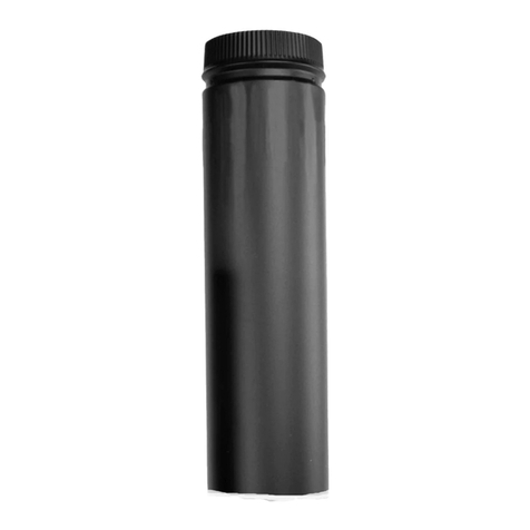
chimney with appropriate black direct vent pipe, and an
adjustable length section.
A typical conversion to an existing masonry chimney is
shown in Figure 6. For installation through the wall of an
existing masonry chimney, a Chimney Outlet Connector
and Flashing are used at the top of the masonry chimney.
The flex pipe liner is connected to the adapter and is
passed down the chimney and out through the masonry
wall. This is attached to the Chimney Inlet Connector
which in turn is attached to the masonry wall and is then
connectedto thedirect ventpipe leadingto the appliance.
MODEL DT DIRECT VENT INSTALLATION
INSTRUCTION SUPPLEMENT
ADAPTING MODEL DT TO FACTORY BUILT AND MASONRY CHIMNEYS
CONVERSION TO A FACTORY BUILT
METAL CHIMNEY
1. Remove the existing chimney cap.
2. Measure the distance from the top end of the chimney
to the bottom of the ceiling support, add 3-inches to this
measurement, and cut a section of flex pipe to that length
(theflex shouldalready be extended to itsnormal length).
3.Connectthe endofthe flex pipesectionto theunderside
oftheChimneyOutlet Connectoryouhaveselected, using
three sheet metal screws. Refer to Figure 2.
4. Pass the flex pipe down through the center of the
chimney system, and center the Outlet Connector on the
topofthe chimney pipe.Drillfour1/8-inch diameterholes
through the adapter, and into the chimney top. Insure
thatyou arein fact,drilling into themetal onthe chimney.
Install the Termination Cap onto the Outlet Connector.
Refer to Figures 3 and 4.
5. Pull the flex pipe down through the ceiling support
box, until it protrudes approximately 3-inches. Connect
the flex pipe to the Chimney Inlet Connector by slipping
it into the sleeve on the top side of the Connector. Use
three sheet metal screws, to assemble these two parts.
6. Push the flex pipe back up into the ceiling support,
center the Chimney Inlet Connector, and attach it to the
support box, or decorative sleeve for double wall solid
packed pipe, with the sheet metal screws furnished. The
holes in the connector are pre-punched. Refer to Figure
5.
7.The connectionbetweentheappliance andtheChimney
InletConnector may becompleted withsections of black
direct vent pipe, together with an adjustable length.
4DT-MCK (Masonry Chimney Conversion Kit)
4DT-CCK (Factory-Built Chimney Conversion Kit)
DIRECT-TEMP®
WARNING
!
Failure to follow the instructions could cause
FIRE, CARBON MONOXIDE POISONING, OR DEATH. If
you are unsure of installation requirements, call the Phone
Numberlistedontheinstructionsorvisitwww.selkirkcorp.com

Termination Cap
ChimneyOutlet
Connector
Existing Metal
ChimneySystem
FlexPipe
ChimneyInlet
Connector
(Adapts to
Support) Any DT Black
Direct Vent Pipe
Fig 1
Fig 2
Fig 3
Fig 4
Chimney Outlet Con-
nector
Sheet metal
Screws Here
Chimney
Outlet Connec-
tor
Termination Cap

CONVERSION TO A MASONRY
CHIMNEY
IMPORTANT: The existing masonry flue opening needs
to have an area of at least 35-square inches to insure
proper intake/exhaust flow.
1.Before cuttingany holes,assemble thedesired sections
of black direct vent pipe to determine the center of the
masonry penetration.
2. Once the center point of penetration has been
determined, cut a 6-inch diameter hole in the masonry.
Be careful, if the hole is too large, the Chimney Inlet
Connector might not mount properly, and if the hole is
too small, then the appliance might starve for intake air.
If there is a frame wall in front of the masonry wall, cut
and frame a 10" clear square opening in wall (centered
around the 6" masonry opening). If there is sheet rock
only (no studs) in front of the masonry, the 10" clear
opening is still needed, but does not need to be framed.
This allows the Chimney Inlet Connector to mount
directly on the masonry and provide clearance to the
combustibles. Refer to Figure 11.
3. Secure the Flashing to the top of the masonry chimney
using a bead of non-hardening mastic sealer. If the
Flashing is larger than the top of the chimney, then cut
and fold flashing as needed to fit chimney.
See Figure 7.
4.Todetermine thelength of flex required, measure from
3" above the top of the Flashing down to the level of the
opening.Add to this measurement the distance from the
centerof the chimney to outthrough the wall. Cut apiece
of 4-inch flex to this length (the flex should already be
extended to its nominal length).
5. Connect the 4-inch flex liner to the Chimney Outlet
Connectorusing three sheetmetal screws.Referto Figure
2.
6. Feed the 4-inch flex liner through the Flashing into the
chimney. Continue to feed the liner out through the
opening in the masonry wall.
7. Secure the Chimney Outlet Connector to the Flashing.
Use three sheet metal screws through the side of the
adapterintothe flangeonthe Flashing, asshownin Figure
8.
8. Install the Termination Cap on to the Chimney Outlet
Connector.
8. Attach the flex to the Chimney Inlet Connector. Use
three sheet metal screws to attach the flex liner to the
Connector. Sec Figure 9.
9. Slide Chimney Inlet Connector against the masonry
wall and secure with masonry bolts. Re-drill larger holes
on connector as needed. Be careful to insure that the
connector is centered in the opening and the mounting
holesline up with the masonry wall. Ifyou havea framed
wall in front of the masonry, use wood screws to mount
the Connector to the framed wall, shown in Figure 11. If
needed,add a section of directvent pipeto the Connector
in order to extend through the opening.
10. The connection between the appliance and the
Chimney Inlet Connector may be completed with the
section of black direct vent pipe, together with an
adjustable length pipe section.
Fig 6
ChimneyInlet
Connector
FlexLiner
Black Direct
Vent Pipe
TerminationTop Chimney Outlet
Connector
Flashing

Fig 7
Fig 8
Fig 9
Fig 10
5030 Corporate Exchange Blvd., SE, Grand Rapids, MI 49512 1-800-992 VENT (8368)
Cut and Bend Flashing
as Appropriate to Fit
Chimney Termination Cap
ChimneyOutlet
Connector
3 Sheet Metal
Screws Here
Flashing
ChimneyInlet
Connector
6” Diameter Hole
inMasonry Wall
ChimneyInlet
Connector
Fig 11
MasonryChimney
Studwall
10” x 10” Framed
OpeninginWall
ChimneyInlet
Connector
Mastic Sealant
Here
0015206 - 0712
This manual suits for next models
1
Other Selkirk Fireplace Accessories manuals
Popular Fireplace Accessories manuals by other brands
RealFlame
RealFlame 310 Instructions and warnings for use
Heat & Glo
Heat & Glo LOGS-I35 Log Placement Instructions

Travis Industries
Travis Industries 98500677 quick start guide

European Home
European Home 95 installation guide
Valor
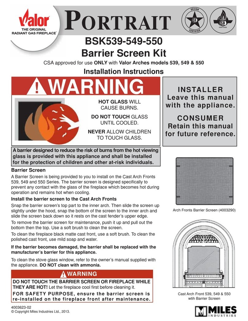
Valor PORTRAIT BSK539-549-550 manual

Napoleon
Napoleon W175-0344 instructions
