Senso AK30 User manual

Instructions Manual
PROCESS INDICATORS

Manual ver 2.0 2

Manual ver 2.0 3
CONTENTS
1. INTRODUCTION 4
1.1 General specifications 4
1.2 Form of order 5
2. INSTALLATION 6
2.1 Preliminary aspects 6
2.2 Input and output configuration 7
2.3. Panel assembly 7
3. INPUTS / OUTPUTS 8
3.1 Signal input options. Examples. 8
3.2 Configuration of the different inputs 10
3.3 Alarms. 11
3.4 Serial Communications ( Optional ) 13
3.5 Auxiliary analogue output( Optional ) 14
4. OPERATION 16
4.1 Introduction 16
4.2 Description of the front 17
4.3 Starting 17
4.4 Loss of power supply 17
4.5 Automatic calibration of the pressure transducer 17
4.6 Tare function 18
4.7 Pressure transducer type 18
4.8 Display filtering function on presure measurement 18
4.9 Limits of the configurable parameters 19
4.10 Parameter configurable values and initial value 22
4.11 General menu diagram 25
4.12 Parameter protection 28
5 TECHNICAL SPECIFICATIONS 29
6 SPECIAL MESSAGES 31

Manual ver 2.0 4
1. INTRODUCTION
This instructions manual describes the installation and operation
of the universal process indicators AK30 and AK32 models.
Read the instructions manual before starting the
unit.
1.1. General specifications
The AK30 is a universal indicator with a configurable input. The
AK32 is a universal indicator with two inputs for the simultaneous
measurement of 2 variables, one configurable and the other for pressure
transducer reading.
Standard:
Totally configurable input for thermocouple, thermoresistance,
voltage, current loop, pressure reading or extensiometric gauge (only
AK30)
5 digit display (AK30) or double 5-digit display(AK32).
2 fully configurable alarms.
Optional:
Modbus RS-485 communications module.
Analogue output proportional to the reading on the indicator
24 V DC power supply for transmitter
Other:
Format: 1/8 DIN43700 (96 x 48 mm, horizontal). Extractable from the
front.
Power supply. 85..265 V AC 50/60 Hz (optionally 21..53 V AC / V DC)
Dimensions: 96 x 48 x 98 mm
Panel drill holes: 91,5 x 45,5 ( ±0,5 )
Display:
AK30:
5 digits 13 mm for the process variable.

Manual ver 2.0 5
2 alarm warning lights
AK32:
Double display 5 digits 10 mm, one for each process.
2 alarm warning lights
Alarms: 2 fully configurable alarms. SPST output( 1A@250 V AC )
Weight:
AK30: 220 g.
AK32: 240 g.
Inputs:
User-configurable as:
L : 0..600°C (Fe-CuNi, DIN43710)
J : 0..600°C (Fe-CuNi, IEC584)
K: 0..1200°C (NiCr-NiAl, IEC584)
N: 0..1200°C (NiCrSi-NiSi, IEC584)
T: 0..400°C (Cu-CuNi, IEC584)
R: 0..1600°C (Pt/13%Rh-Pt, IEC584)
S: 0..1600°C (Pt/10%Rh-Pt, IEC584)
RTD, Pt100: -200..600°C (IEC751)
RTD, Pt100: -99,9..200,0°C (IEC751)
Current loop 0..20 , 4..20 mA (load 150 ohm)
Voltage V DC 0..5 , 0..10 V (Impedance >1 Mohm)
Pressure transducer
Extensiometric gauge 350 ohm( only AK30 )
1.2. Form of order
Model Options Power supply Language
0: No options
1: Analogue output with
AK35
2: Standard
communications
Modbus/RS-485 with
AK36
3: 24 V DC power supply for
transmitter with AK37
1: 85..265 V AC, 50/60 Hz
2: 21..53 V AC / V DC
AK30 1 1
AK32 1 1

Manual ver 2.0 6
2. INSTALLATION
2.1. Preliminary aspects
The unit is connected with the instrument installed in its final
place of use. To avoid electrical discharges while connecting, connect
the instrument to the power supply in the last wiring operation. The
installation must include at least one 1ª, 250 V bipolar switch, which must
be close to the instrument and easily accessible for the operator. It must
be marked as an instrument switch. Likewise, a 200 mA, 250 V fuse must
be installed in the power supply wiring (isolation cable of at least 1000 V).
The following recommendations should be followed as far as
possible:
-The instrument must be connected in the absence of power supply.
-Do not install the instrument close to moving parts, contacts or
motor starters.
-Try to avoid mechanical vibrations.
-For the signal lines, it is recommendable to use a screened cable
with a ground connection at a single point.
-It is important to check the configuration of the instrument if any
problem appears in the starting.
Any installation or use of the instrument other than that specified
in this manual may affect the protection levels of the unit.
Power supply

Manual ver 2.0 7
2.2. Input and output configuration
The instruments of the are entirely configurable, so it is necessary
to make sure before starting that the configuration of the instrument
corresponds to the application for which it is intended.
Follow the steps in chapter 3 to change the configuration of the
input or sensor signal.
2.3. Panel assembly
The instrument must be installed in a panel with a maximum
thickness of 8 mm. Its location must be subject to as little vibration as
possible and it must be ensured that the ambient temperature remains
between 0 and 50ºC.
Insert the instrument in the panel hole and hold it firm while, with
a screwdriver, you tighten the fixing clips on the interior wall of the panel.
To install more than one instrument, a minimum separation must be left
between instruments of 10 mm vertically and 20 mm horizontally.

Manual ver 2.0 8
3. INPUTS / OUTPUTS
3.1. Signal input options.Examples.
This chapter diagrammatically describes the connection of the
different options for the input signal.
Thermocouple input connections
Thermosresistance input connections

Manual ver 2.0 9
Connection for the linear voltage input
Connection for the linear current input
Connection for the pressure transducer
input

Manual ver 2.0 10
Connection for the extensiometric
gauge input
3.2 Configuration of the different inputs
Each instrument is default configured for a type J input (Fe-
CuNi). It is possible to change the set-up of the type of input simply with
the INP parameter from the menu. In the AK32, the second channel
always shows the reading of the pressure transducer.
INP
Value
Meaning
0 J : 0..600°C (Fe-CuNi, IEC584)
1 L : 0..600°C (Fe-CuNi, DIN43710)
2 K: 0..1200°C (NiCr-NiAl, IEC584)
3 N: 0..1200°C (NiCrSi-NiSi, IEC584)
4 T: 0..400°C (Cu-CuNi, IEC584)
5 R: 0..1600°C (Pt/13%Rh-Pt, IEC584)
6 S: 0..1600°C (Pt/10%Rh-Pt, IEC584)
7 RTD, Pt100: -200..600°C (IEC751)
8 RTD, Pt100: -99,9..200,0°C (IEC751)
9 Voltage V DC 0..5 V (Impedance >1 Mohm)
10 Voltage V DC 0..10 V (Impedance >1 Mohm)
11 Current loop 0..20 mA (load 150 ohm)
12 Current loop 4..20 mA (load 150 ohm)
13 Pressure transducer ( only AK30 )
14 Extensiometric gauge 350 ohm( only AK30 )

Manual ver 2.0 11
3.3 Alarms.
The AK30 and AK32 include 2 alarms. In the case of the AK32,
these alarms may be associated independently with the required
channel using the Ch.A1 and Ch.A2 parameters. Channel 1 corresponds to
the configurable input and channel 2 to the pressure input. The alarm
output is by relay with SPST contacts (one voltage-free contact). The
alarm outputs are as follows:
The working configuration of the alarms is performed by means
of the C.A1 and C.A2 parameters.
1) Type of activation.
High Alarm: The alarm is activated when the process variable is
equal to or higher than the consignment point of the alarm. For
instance, if the consignment point of the alarm is at 450°C, the alarm
will remain on as long as the temperature is greater than or equal to
450ºC.
Low Alarm: The alarm is activated when the process variable is equal
to or lower than the consignment point of the alarm. For instance, if
the consignment point of the alarm is at 450°C, the alarm will remain
on as long as the temperature is lower than or equal to 450ºC.
2) Type of action.
Direct Action: The output relay is usually off and is activated when
the alarm activation condition is caused.

Manual ver 2.0 12
Inverse Action: The output relay is usually on and is deactivated
when the alarm activation condition is caused.
By combining the type of activation and the type of action, it is
possible to configure the following alarm operation modes:
Configuration C.A1/2Working mode
0 Alarm disabled
1 High alarm, direct action
2 High alarm, inverse action
3 Low alarm, direct action
4 Low alarm, inverse action
The alarm hysteresis can be set up using the HY.A1 or HY.A2 parameter. This
hysteresis is used so that an activated alarm is not deactivated until the margin
indicated from the consignment point has been exceeded. The following graphs
show the behaviour of a high and low alarm with hysteresis.
Hysteresis
with high
alarm
Alarm
deactivated
Alarm activated Alarm
deactivated
Hysteresis
with low
alarm
The activation of each alarm may be set up so that it is only
activated once the activation condition has been fulfilled for a period of
Manual ver 2.0 13
time of up to 20 seconds. This is achieved using the dLy.A1 and DLY.A2
parameters. If these parameters are 0, the activation is instantaneous.
Also included is a working mode where the alarm is kept off
while the alarm condition is not fulfilled (masked alarm). Once the alarm
condition is not fulfilled for the first time, the alarm works as normal. This is
useful when a low alarm is configured and we do not want it to be
activated until a working area has been entered. This working mode is
activated with the NAs.A1 and NAs.A2 parameters. Once activated, this
mode is entered without the instrument having to be turned on once
more. When the instrument is turned on again, this mode will be started.
The alarm deactivation may be set up as manual or automatic.
If an alarm is triggered with manual deactivation, it will not be
deactivated until the instrument is told explicitly. This configuration is
performed with the Lch.A1 and Lch.A2 parameters. To activate the alarm
manually, the and keys must be pressed simultaneously.
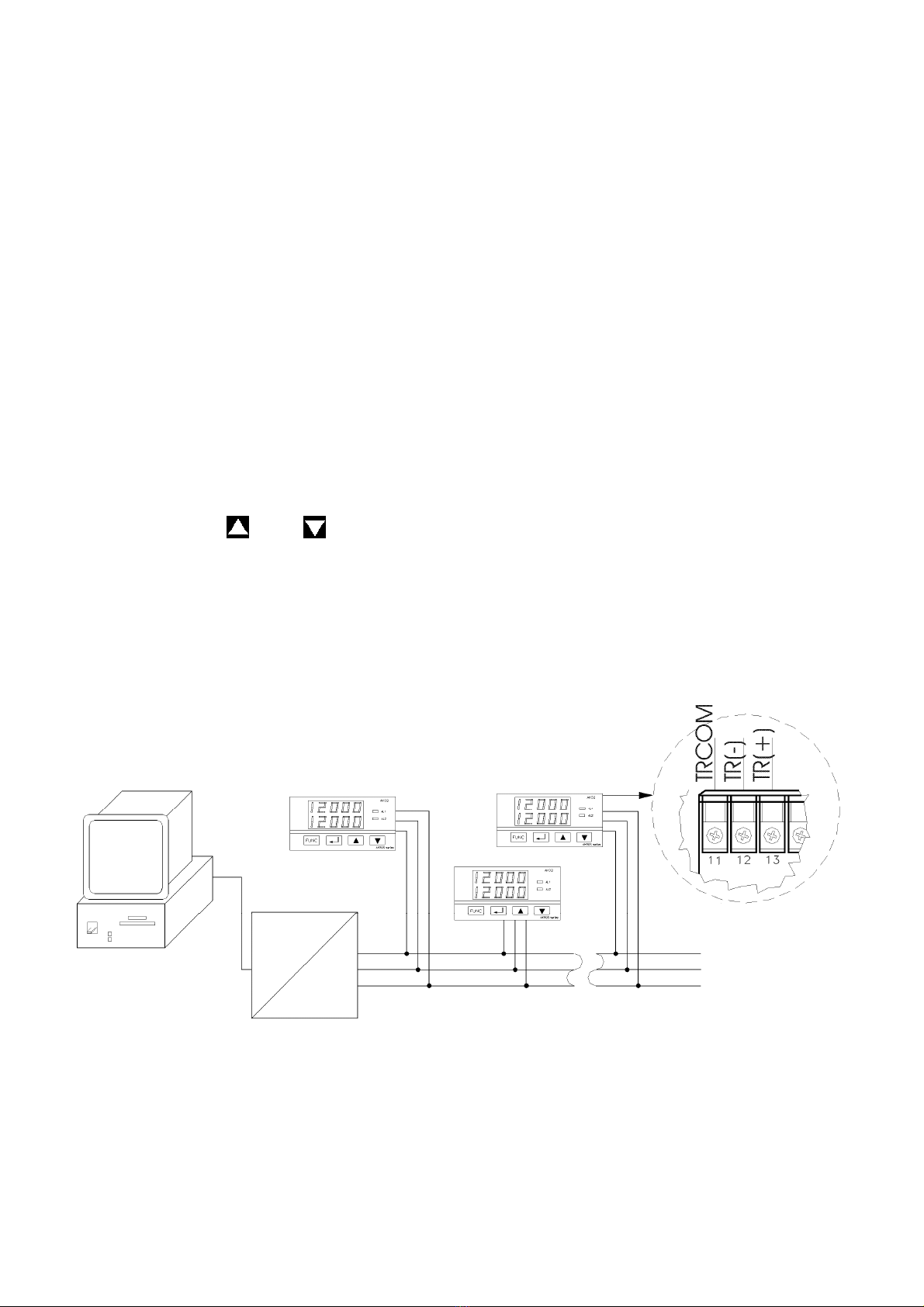
3.4 Serial Communications ( Optional )
The serial communications interface is RS485, 2 starnds + ground,
half duplex.Once installed, this interface is activated on assigning the Opt
parameter to 1.
There is a specific instructions manual for the interface and
communications protocol.

Manual ver 2.0 14
3.5 Auxiliary analogue output( Optional )
The auxiliary analogue output may be 0..20 mA, 4..20 mA, 0..5 V
or 0..10 V and the option must be configured both in the module
provided and in the indicator. Once installed, this interface is activated
on assigning the value 2( 0..20 mA ), 3( 4..20 mA ), 4( 0..5 V ) or 5( 0..10 V )
to the Opt parameter.
Once activated, the analogue output may be set up as direct
or inverse and the variation margin of the signal may also be set up by
the user.
Direct Output ( AOut.S = 1 )means that the value of the output signal
increases along with the process variable.
Inverse Output ( AOut.S = 0 )means that the value of the output signal
falls as the process variable increases.
Likewise, it is possible to set up the minimum ( AOut.L ) and
maximum ( AOut.H ) value of the process variable between which the
analogue output will vary between its minimum and maximum.
For example, an instrument with a type J thermocouple input
has a scale of 0..600°C. If this instrument has an analogue output of 4..20
mA, it is possible to set up AOut.L = 100°C and AOut.H = 500°C with which
the analogue output will take the following values:
Process (°C) Direct
Analogue
Output (mA)
Inverse
Analogue
Output (mA)
0 4,0 20,0
100 4,0 20,0
200 8,0 16,0
300 12,0 12,0
400 16,0 8,0
500 20,0 4,0
600 20,0 4,0

Manual ver 2.0 15
In the Ak32, it is possible to set the channel associated to the
digital output by means of the Set.Ch parameter. Channel 1 corresponds
to the configurable input and channel 2 corresponds to the pressure
input.

Manual ver 2.0 16
4. OPERATION
4.1 Introduction
The indicators may be completely set up by means of a series of
parameters accessible from a menu. The availability of some parameters
depends on the current set-up of the instrument and the model. Point 4.7
describes all the configurable parameters and point 4.9 graphically
displays the route necessary to access each of the parameters.
The operation of the menus is controlled by means of 4 keys with
the following function:
: Function key. It is used to enter the menu or to pass to the
following parameter if we are already in this menu.
: It serves to increase the value of a parameter. If it is held
down, every 10 increments the speed of the increase rises. In the
case of an AK30 set up as an extensiometric reader, if it is held
down for 3 seconds from outside the menu, the value of the
current reading is taken as a Tare. When the instrument is
applying a tare, this is indicated by means of a point that flashes
on the last digit.
: It serves to decrease the value of a parameter. If it is held
down, every 10 decreases the speed of the decrease rises. In
the case of an AK30 set up as an extensiometric reader, if it is
held down for 3 seconds from outside the menu, the value of the
Tare is eliminated.
: Confirmation key. This must be pressed each time a change
made to a parameter is to be confirmed. The instrument will
flash to indicate that the parameter has been saved. All of the
parameters that depend on the modified parameter are
updated in order to be consistent. If it is held down in an AK30
set up as a pressure transducer reader or in an AK32, we enter
the automatic transducer calibration mode. At the end of this
mode, confirmation is requested of the new calibration.

Manual ver 2.0 17
4.2 Description of the front
In addition to the front keys described in the previous aside,
there are 2 alarm warning lights labelled as AL1 and AL2.
4.3 Starting
On connecting the power supply, the instrument shows the
message tESt moving through the displays while all the internal
parameters are started.
4.4 Loss of power supply
All of the working parameters of the instrument are stored in an
internal memory. When the power supply returns, it will return to the
operating mode in which it was before.
4.5 Automatic calibration of the pressure transducer
This indicator has an automatic self-calibration function for
pressure transducers that enable this. In the AK-32, this function is always
available, whereas in the AK-30 it is only available when the input probe
is set up as a pressure transducer InP = 13 ).
To activate the self-calibration, the must be held down for 3
seconds. Firstly, the zero value of the transducer is calibrated, and then
the value of 80% of the scale base. If the transducer is subject to pressure
when the zero value is calibrated, the calibration will not be correct.
At the end of the self-calibration, the message SAUE appears if
the measurements taken are correct. By pressing the new calibration
is confirmed, whereas by pressing , it is discarded. If the
measurement taken in the zero and that taken at 80% of the scale base
are not correct, the FAiL message appears.

Manual ver 2.0 18
4.6 Tare function (only available in AK-30 using an
extensiometric gauge)
This indicator allows a tare to be added to the measurement
when it is set up with a gauge input. To activate a new tare, hold down
the key. Once activated, the tAr.On message appears and the
decimal point of the last digit flashes, indicating that the indicator is
adjusted. To deactivate the tare, press the key for 3 seconds. On
deactivating it, the tAr.Of message appears.
4.7 Pressure transducer type
The tyPE parameter let you cose between 3 different pressure
transducer types with different input margins and auto-calibration
options. The following table shows the meaning of the different values
from tyPE.
tyPE Meaning
0 Pressure transducer with
input margin from -3 mV to
37 mV and auto-calibration
of 0 and 80%
1 Pressure transducer with
input margin from 0 mV to
100 mV and auto-
calibration of 0 and 80%
2 Pressure transducer with
input margin from 0 mV to
100 mV and auto-
calibration of 0%
4.8 Display filtering function on presure measurement
Setting the Filtr parameter to 1 activates filtering the value
shown in the display when measuring pressure. The objective of this filter
is to make the displayed measure more stable when working on fast
changing enviroments. The filter only affects to the displayed
measurement, that is, other functions still use the real measured
signal(alarm activation, analog output,…).

Manual ver 2.0 19
4.9 Límites de los parámetros configurables
SP.A1 Alarm consignment point 1
Minimum value:
Probe selected Value
Thermocouple Minimum probe value
Thermoresistance Minimum probe value
Linear input( V o mA ) in.L parameter
Pressure transducer -10% scale base
Extensiometric gauge (AK30) 0
Maximum value:
Probe selected Valor
Thermocouple Maximum probe value
Thermoresistance Maximum probe value
Linear input( V o mA ) in.H parameter
Pressure transducer FSV
Extensiometric gauge(AK30) FSV
SP.A2 Alarm consignment point 2
Minimum value:
Probe selected Value
Thermocouple Minimum probe value
Thermorresistance Minimum probe value
Linear input( V o mA ) in.L parameter
Pressure transducer -10% scale base
Extensiometric gauge(AK30) 0
Maximum value:
Probe selected Value
Thermocouple Maximum probe value
Thermorresistance Maximum probe value
Linear input( V o mA ) in.H parameter
Pressure transducer FSV
Extensiometric gauge(AK30) FSV
C.A1 Alarm configuration 1
Minimum value: 0
Maximum value: 4
C.A2 Alarm configuration 2
Minimum value: 0
Maximum value: 4
Hy.A1 Alarm hysteresis 1(only visible if C.A1 ≠0 )
Minimum value: 0
Maximum
value:
If alarm configured low SP.A1 – Probe Low Limit
If alarm configured high Probe High Limit – SP.A1
Hy.A2
Alarm hysteresis 1(only visible if C.A2 ≠0 )
Minimum value: 0
Maximum
value:
If alarm configured low SP.A1 – Probe Low Limit
If alarm configured high Probe High Limit – SP.A1

Manual ver 2.0 20
Ch.A1 Alarm channel 1 ( only visible in AK32 if C.A1 ≠0 )
Minimum value: 1
Maximum value: 2
Ch.A2 Alarm channel 2 ( only visible in AK32 if C.A2 ≠0 )
Minimum value: 1
Maximum value: 2
Mas.A1 Alarm mask 1 ( only visible if C.A1 ≠0 )
Minimum value: 0
Maximum value: 1
Mas.A2 Alarm mask 2 ( only visible if C.A2 ≠0 )
Minimum value: 0
Maximum value: 1
dLy.A1 Alarm wait 1 ( only visible if C.A1 ≠0 )
Minimum value: 0
Maximum value: 300
dLy.A2 Alarm wait 2 ( only visible if C.A2 ≠0 )
Minimum value: 0
Maximum value: 300
Lch.A1 Alarm manual deactivation 1 ( only visible if C.A1 ≠0 )
Minimum value: 0
Maximum value: 1
Lch.A2 Alarm manual deactivation 2 ( only visible if C.A2 ≠0 )
Minimum value: 0
Maximum value: 1
Bias1 Channel bias 1
Minimum value: -9999
Maximum value: 99999
Bias2 Channel bias 2(only visible in AK32)
Minimum value: -9999
Maximum value: 99999
INP Channel input probe 1
Minimum value: 0
Maximum value:
14 in AK30
12 in AK32
Unit Unit ( only visible if INP <= 8 )
Minimum value: 0
Maximum value: 1
Dp Position of the decimal point ( only visible if INP >= 9 )
Minimum value: 0
Maximum value: 3
in.L A lower value for the scale of linear signal inputs ( only visible
if INP = 9, 10, 11, 12 )
Minimum value: -9999
Maximum value: In.H -1
in.H
A higher value for the scale of linear signal inputs ( only visible
if INP = 9, 10, 11, 12 )
Minimum value: in.L + 1
Maximum value: 99999
This manual suits for next models
1
Table of contents
Other Senso Measuring Instrument manuals

Popular Measuring Instrument manuals by other brands


Anritsu
Anritsu 11 Series Operating and maintenance manual

az-instrument
az-instrument AZ8903 Operation manual

Masibus
Masibus PM2160-A user manual

KROHNE
KROHNE GA24 Supplementary instructions

Endress+Hauser
Endress+Hauser Waterpilot FMX11 operating instructions

Burster
Burster RESISTOMAT 2329 Operation manual


