Sen Source PC-TB12N-W User manual

PC-TB12N-W Software and Manual
Product Overview
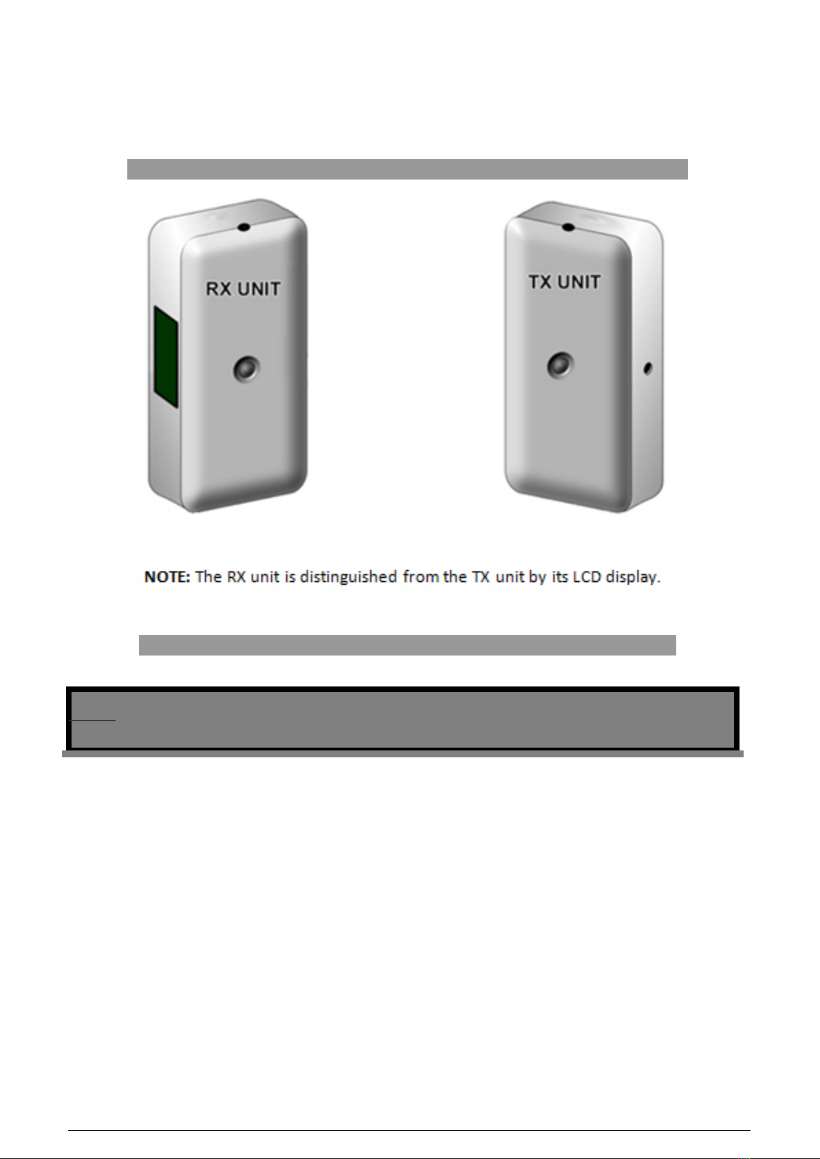
The PC-TB12N-W is a complete, self-contained, battery-operated people counter with an integral WiFi-enabled 802.11b data transmitter. This system consists of a photoelectric IR beam transmitter and receiver, which can operate up to 30 ft apart in front- or side-firing modes. The
counter will increment as the invisible IR beam is broken, regardless of the direction of traffic. The selectable group-counting feature counts groups of people as one unit, instead of counting individuals. The receiver has an integrated six-digit LCD counter for stand-alone use. This counter provides an easily installed, comprehesive network solution for local and/or central data collection.
Features:
Battery or Plug-in, self-contained counter with 802.11b Wi-Fi data transmitter installs in minutes
Six digit LCD display indicates setup parameters, battery life, and counter value
USB Configurable Options Include:
o Wireless Security & Network Options Include DHCP or Static IP, WEP or WPA2
o Adjustable High/Low sensing range to extend battery life
o Selectable group counting feature will count a group of people as one unit instead of counting individuals
o Front-Firing (Opposing Wall mount) or Side-Firing (Door-Frame Mount) in one unit
Use a PC-SSRX485 Sensor Server for easy data retrieval and system monitoring at corporate and/or store level.
Ordering P/N
PC-TB12N-W (with light grey enclosure, shown above)
PC-TB12N-WB (with black enclosure)
1 / 11

Parameters
MIN TYP MAX UNITS
IR Sensor Range (Selectable 10ft or 40ft max)
- 10 30 Feet
Battery life IR transmitter
1 1.2 1.7 Years
Battery life IR receiver
1 2 4 Years
Battery type
(Qty 4) 3.6v AA Lithium, 2x Each
Old sensors used 1.5v AA size batteries - no longer supported.
Enclosure (designed for indoor use only)
2.0w” x 4.3L” x 1.2H” ABS (CYCOLAC) Plastic
Caution
Light: Direct sunlight or automobile headlights may cause false counts
Impact/Shock: Heavy impact or shock may cause damage to hardware
Tampering: Changes or modifications, not expressly approved by SenSoure, will void
the warranty
Cleaning: Harsh cleaners, such as paint remover or benzene, may ruin the surface.
Use a soft, wet cloth and mild soap or detergent to clean displays and lenses
Software Installation
Note: If the sensors are being used in side-firing mode, as stand-alone counters
without WiFi data collection, skip the software installation and go directly to the
hardware installation
section.
1. Download the software set up utility tool here TB12 Programming Utility
2. Once it is downloaded, you can either access the WifiSensorUtilitySetup from a pop-up window, or by navigating to the default download location:
C:\Documents and Settings\Your Name Here\My Documents\Downloads
2 / 11
5. Double-clicking the installer packaging icon will load the installation pop-up window. Follow the prompts to complete software installation.
6. Proceed to the initial configuration of the units before launching the WiFi Sensor Utility program.
RX and TX Sensor Units
Sensor Configuration
RX Unit Configuration
3 / 11
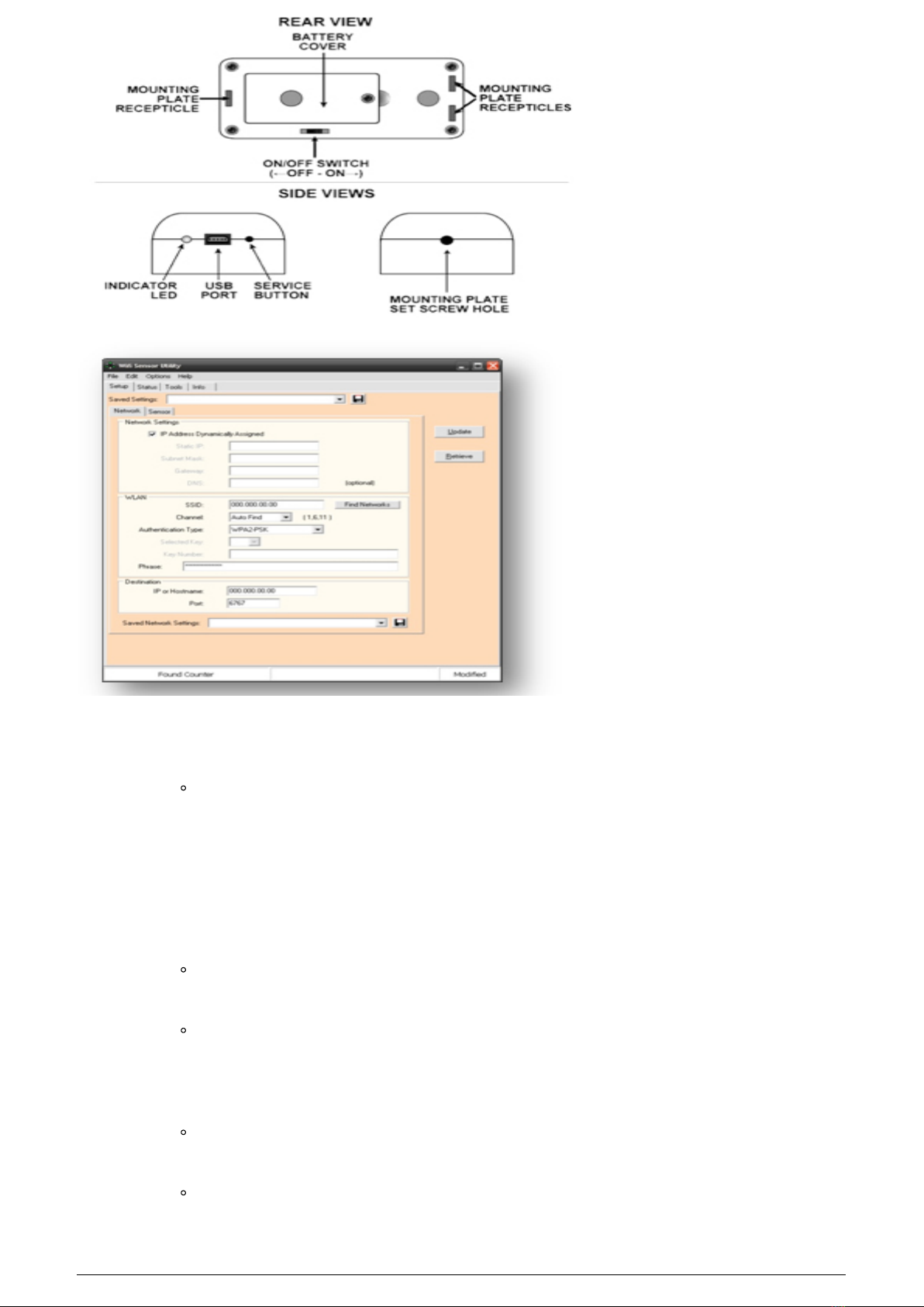
1. Power on the RX sensor unit by using the small, blue screwdriver to move the power
ON/OFF swtich.
If looking at the rear view of the unit, as indicated by the figure on the right,
switch will move RIGHT.
Note: The RX unit’s LCD display will not show a number on power-up, but will indicate a
current value when the Service Button is activated or the beam is broken.
2. Connect the USB cable to the RX unit and the PC.
3. Use the small, blue screwdriver to activate the Service Button by gently pushing on it
once.
The LCD display will read “CONFIG” to confirm that the unit is now in
Configuration Mode and ready to be setup via the WiFi Sensor Utility
Start Menu >> All Programs >> Wifi Sensor Utility (folder) >> Wifi
Sensor Utility
Note: The sensor will not broadcast data while in Configuration Mode.
4. Setup Tab: Test the connection by clicking the “Retrieve” button on the right.
If the connection has been properly made, a pop-up window will display stating,
“Sensor Parameters Retrieved”.
The following RX unit settings can be modified:
4 / 11
Network Tab*:
IP Address Dynamically Assigned: Check if the sensors will
receive their IP address dynamically (DHCP), instead of static.
Static IP, Subnet Mask, Gateway, DNS.
WLAN SSID: Enter the information for the 802.11 network to be
used for network communication. (Use Find Networks to locate
available wireless networks.)
WLAN Channel: Use Auto Find to modulate between channels 1,
6, and 11 – or match the channel set to the router or access point.
WLAN Authentication Type: Select the encryption type [None,
WEP-128 (Selected Key and Key Number), or WPA2-PSK (Phrase)].
Destination IP or Hostname: Enter the IP address for the
Sensor Server that will be collecting data
Destination Port: Enter the port used by the Sensor Server to
receive UPD packets. If you have not changed the default settings
on the Sensor Server, do not change the value from 6767.
The Network Tab is for use only with a Sensor Server for data
collection. It is not for a stand-alone system.
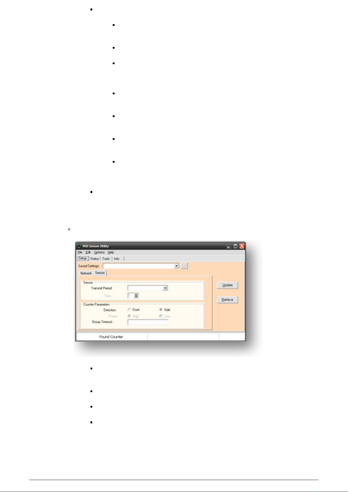
The Sensor Tab
Transmit Period: A shorter transmit period allows the sensor to
broadcast more often, at the expense of battery life.
Direction: Choose Front-Firing or Side-Firing.
Power: is for use with the TX unit only.
Group Timeout: Set the count delay fo the sensor in values of seconds.
For normal counting, leave the timeout at zero. To count families and
other groups as units, increase the delay time
5 / 11
The Update Button: Whenever a change is made on the Setup tab, the bottom, right-
hand side of the status bar will read “Modified”. To save the changes to the sensor, click
the Update button. To save a copy of the settings to the computer, enter a name in the
Saved Settings field, and click the Save (floppy disk) icon.
The Retrieve Button: To download the sensor’s current settings, click the Retrieve
button.
The Status Tab: Used for the RX unit to verify the sensor is connecting to the network,
check the IP settings, and view the estimated batterly life.
Click the Get button to retrieve settings from the sensor.
Click the Reboot button to reboot the sensor.
The Tools Tab: Provides simple troubleshooting tools for the RX unit.
Ping From Sensor or Ping From This PC to test whether the IP can be reached
and to test for communication latency (packet round-trip time).
TX Unit Configuration
1. Power on the TX sensor unit by using the small, blue screwdriver to move the power
ON/OFF switch.
2. Connect the USB cable to the TX unit and the PC.
3. Use the small, blue screwdriver to activate the Service Button by gently pushing on it
once.
4. Setup Tab: Test the connection by clicking the “Retrieve” button on the right.
If the connection has been properly made, a pop-up window will display stating, “Sensor
Parameters Retrieved”.
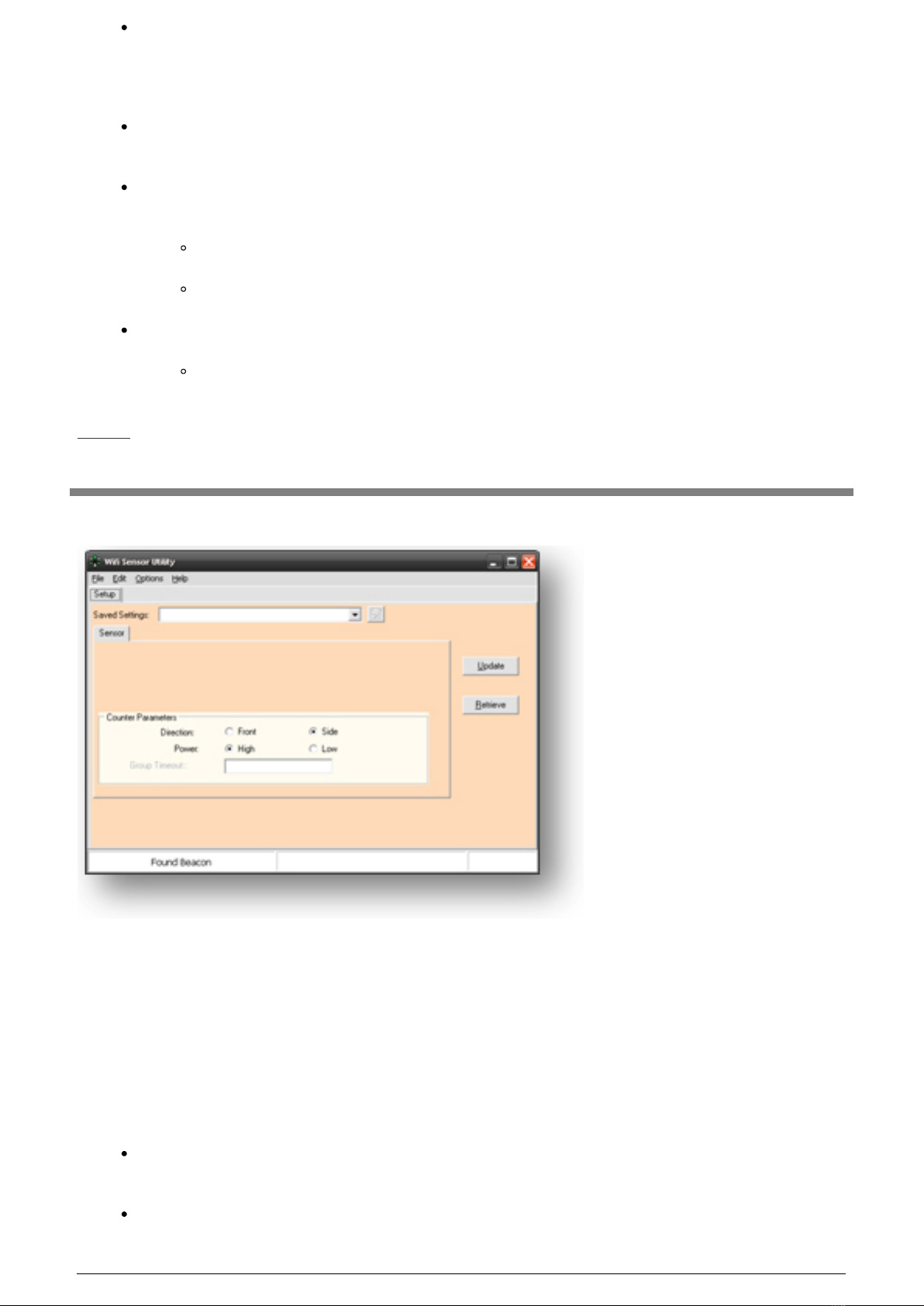
The following TX unit settings can be modified
6 / 11
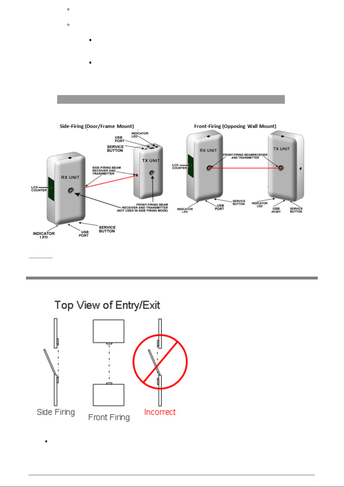
Direction: Choose Front-Firing or Side-Firing.
Power
High: Allows a separation between the RX and TX units of up to 40 feet,
at the expense of battery life (approximately 1.2 years).
Low: Allows a separation between the RX and TX units of up to 12 feet,
providing maximum battery life (1.7 years).
Hardware Installation
Sensor Mounting Overview
The sensors must be mounted so that they are no more than 40 feet apart (if being used
in high-power mode) or 12 feet apart (if being used in low-power mode).
7 / 11
The sensors should be mounted 3-4 feet off the ground to count all traffic, or 4-5
feet off the ground to count only adult traffic.
The mounting surface should be sturdy in order to prevent misalignment from
bumping into either the sensor or mounting bracket.
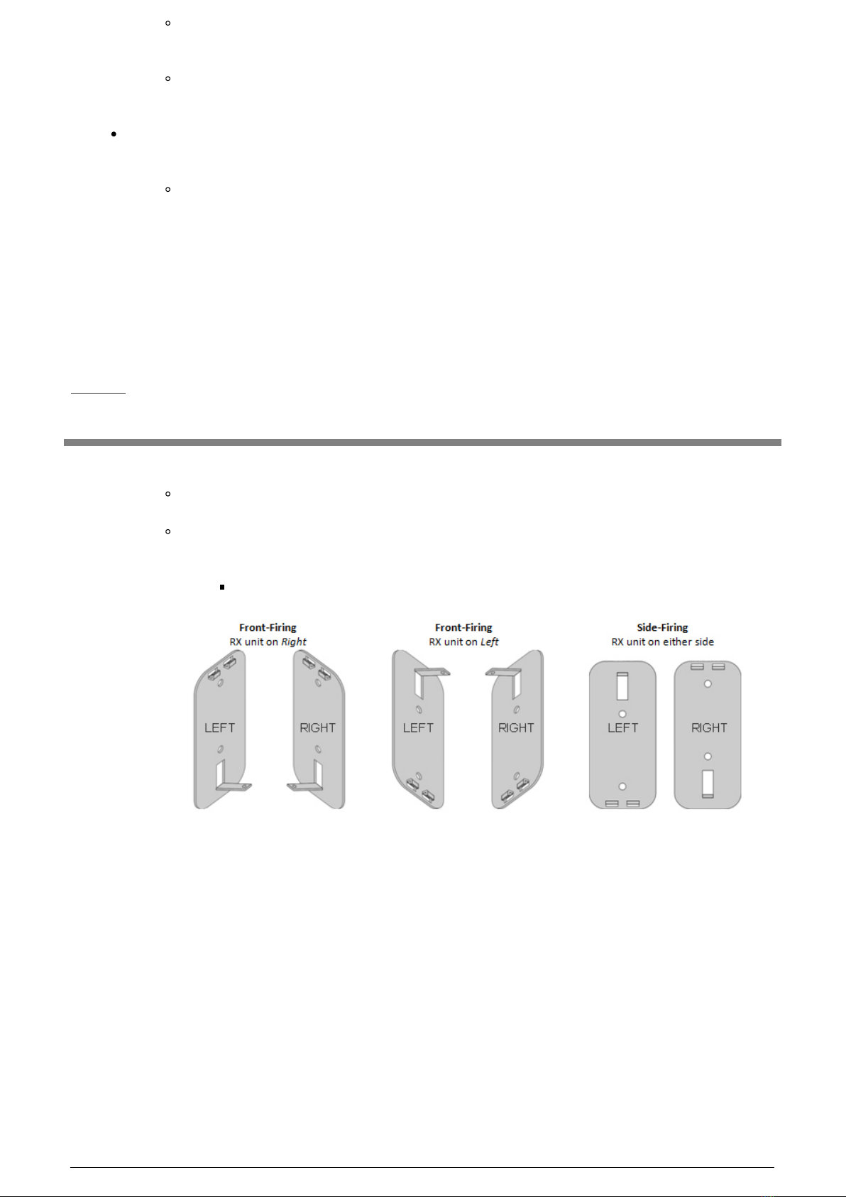
The image on the right provides examples of both correct and incorrect mounting for
either Side-Firing or Front-Firing configurations.
Door handling (door swing) must be taken into consideration before mounting the
sensors (especially true for Side-Firing mode, where sensors are typically
mounted on the doorframe). Ensure that the door does not break the beam when
it opens/closes.
Back-Plate Configuration
1. Mount the sensor back-plates to the desired surface (before attaching the sensor units).
If the LCD Display is to be used, the orientation of the back-plate is critical
Determine if the sensors will be used in Front- or Side-Firing mode, and if the RX
unit is to be mounted on the left or right.
Refer to the following diagram.
8 / 11
2. Power on the RX and TX sensor units (if you have not done so already) by using the
small, blue screwdriver to move the power ON/OFF switch.
The ON/OFF switches will not be accessible once the sensors are mounted.
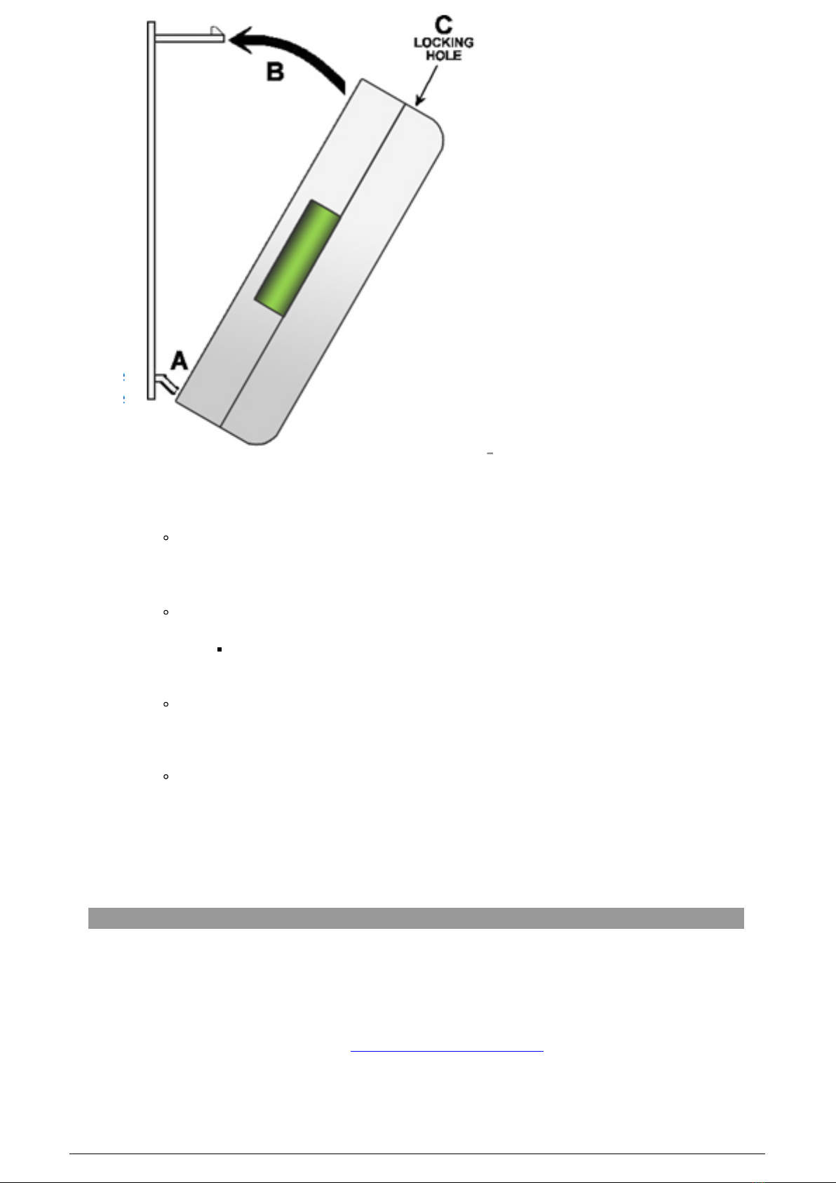
3. Attach the sensors to the back-plates
Insert the dual tabs at point A into the receptacles on the back of the sensor.
The sensor must be initially tilted at an angle, as shown in the image on
the right.
Once the tabs are inserted, tilt the other end of the sensor toward the back-plate
– inserting the larger, single tab at point B into the receptacle on the back of the
sensor.
When the tabs are in place, slowly apply some force to snap the senor onto the
back-plate.
Note: To remove the sensor from the back-plate, use the small, blue screwdriver
to push on the locking tab in the small hole at point C, while pulling slightly on
the sensor to release it from the back-plate.
Data Collection Using the Sensor Server
Note: If the PC-TB12N-W will be used with a previously purchased Sensor Server, the Sensor
Server firmware version (found on the Server ID tab of the Server Manager software) must be
version 2.6a or later. Previously purchased Sensor Servers must also be configured to receive
UPD packets over the network. Please contact SenSource technical support for assistance by
phone at 800.239.1226 or via e-mail at [email protected]
1. Install the Sensor Server and Server Manager software according to the Quick-Start
guides provided with the hardware and software.
9 / 11

2. Place the Server into Service Mode, as instructed in the Help files.
3. Send a service signal from the RX unit by activating the Service button on the RX until
the LED indication flashes briefly.
4. The sensor will then be added to the Sensor Server. Refer to the Server Manager Help
files for instructions on viewing received data.
Using the Sensors as Stand-Alone Units(No Data
Collection)
RX Unit Functions
Reading the current counts: When the IR beam of the PC-TB12N-W is broken, the LCD
counter on the RX unit will display the current count value for two seconds.
To view the counts without breaking the beam, activate the Service button on the
RX unit (until the LED indicator flashes briefly). The LCD counter will then
display the current total count, as well as an F or S, indicating which mode (front-
or side-firing) is being used. This also sends a service signal when using the
Sensor Server.
Clearing the LCD Counter: The counter may be reset by activating the Service button
until the counter indicates a zero count (approximately 4 seconds).
Reset Battery Meter: If battery life will be monitored using the WiFi Sensor Utility
software or the Sensor Server, the battery meter must be reset whenever the batteries
are replaced.
The battery meter is reset by activating the Service button until the LCD display
indicates “NEW BATT” (approximately 8 seconds).
Configuration Mode: The RX unit must be placed in configuration mode to change
settings with the WiFi Sensor Utility.
To place the unit into Configuration Mode, connect the sensor to the computer
with the USB cable and activate the Service button.
TX Unit Functions
Indicate Mode: Briefly activating the Service button and releasing it (less than 1
second), will allow the TX unit to indicate the programmed mode of operation. The LED
will flash 1 to 4 times, depending.
1 flash = Front-Firing, Low power
2 flashes = Front-Firing, High power
3 Flashes = Side-Firing, Low power
4 Flashes = Side-Firing, High power
10 / 11

Reset Battery Meter: If battery life will be monitored using the WiFi Sensor Utility
software or the Sensor Server, the battery meter must be reset whenever the batteries
are replaced.
The battery meter is reset by activating the service button until the LED stays on
(approximately 8 seconds).
Configuration Mode: The TX unit must be placed in configuration mode to change
settings with the WiFi Sensor Utility.
To place the unit into Configuration Mode, connect the sensor to the computer
with the USB cable and activate the Service button.
Powered by TCPDF (www.tcpdf.org)
11 / 11
Table of contents
Other Sen Source Cash Counter manuals


