Senco Smart Bridge User manual

Verpa Senco BV
Pascallaan 88
8218 NJ Lelystad
The Netherlands
EMEA: www.senco-emea.com
© 2014 by Senco Brands, Inc.
Operating Instructions
(Translation of Original Instructions)
Gebruiksaanwijzing
(Oorspronkelijke Gebruiksaanwijzing)
Manuel utilisateur
(manuel original)
Smart Bridge
Smart Bridge
SBM_28-11-2014

2
GB
NL
English 3
Nederlands 19
FR Français 35

3
GB
TABLE OF CONTENTS
1 Foreword 4
2 Introduction 4
2.1 Users 4
3 Purpose and function of the Smart Bridge 4
4 Safety 5
4.1 Symbols used 5
4.2 Safety rules 5
5 Operation 6
5.1 Depth adjustment 6
5.2.1 Manual height adjustment 7
5.2.2 Automatic height adjustment (optional) 7
6 Operation 8
6.1 Switching tacker units on and off 8
6.2 Bringing tacker units in correct position for tacking in the X-direction 8
6.3 Moving tacker units in the Y-direction 8
6.4.1 Tacking distance in the X-direction for manual height adjustment 9
6.4.2 Tacking distance in the X-direction for automatic height adjustment (optional) 9
6.5 Tacking in X-direction 9
6.6 Positioning tacker units for tacking in the Y-direction 10
6.7.1 Tacking distance in the Y-direction for manual height adjustment 10
6.7.2 Tacking distance in the Y-direction for automatic height adjustment (optional) 10
6.8 Tacking in Y-direction 11
7 Maintenance 11
8 Malfunctions 12
9 Technical data 13
10 Parts of Smart Bridge 14
10.1 Smart Bridge total 14
10.2 Smart Bridge tacking waggon 15
10.3 Smart Bridge X-drive 16
10.4 Smart Bridge Y-drive 17
10.5 Smart Bridge X-drive 18
Guarantee 35
EC Declaration of Conformity 36
Please read this manual and the manual for the installed tool carefully before using the machine!

4
GB
4
1 Foreword
This documentation is a manual and describes the mechanical aspects of the Smart Bridge.
This documentation is part of the Smart Bridge. When transferring the installation, the documentation must be handed
over.
Keep this documentation in a safe place; it contains information that can be useful or necessary later, for example, for
repair work or maintenance.
Work activities that must be performed by personnel from Senco are not included in this documentation.
Using this documentation.
The instructions are categorised according to the type of user of the installation.
The following terms are used:
User
This is the daily user of the installation.
Service personnel
Persons with training, experience and tools that are required for the described work activities.
Safety ofcer
The person who is responsible for the working conditions in the company of the user. If nobody has been appointed for
this purpose, this will be the employer himself.
Work activities that are not included in this documentation must be performed by Senco personnel.
FOREWORD
INTRODUCTION
2 Introduction
This installation is designed and constructed so that it can be safely maintained and used. This applies to the use, the
conditions and the regulations, as described in this documentation. Reading and adhering to this documentation and
complying with the instructions are therefore necessary for everyone who works with or on this installation. In the event of
professional use, the safety ofcer or employer is responsible for ensuring that the relevant persons are fully familiar with
and comply with these instructions.
In this documentation, a distinction is made between normal use and other work activities. The reason for this is that,
especially with regard to safety, the service personnel are subject to other requirements than the users.
The adjustments and/or settings must be performed by qualied service personnel.
2.1 Users
The installation can be operated by any adult person who is conversant with and observes the content of safety and
operating instructions. The safety ofcer checks that the user is capable of using and has adequate knowledge of the
installation.
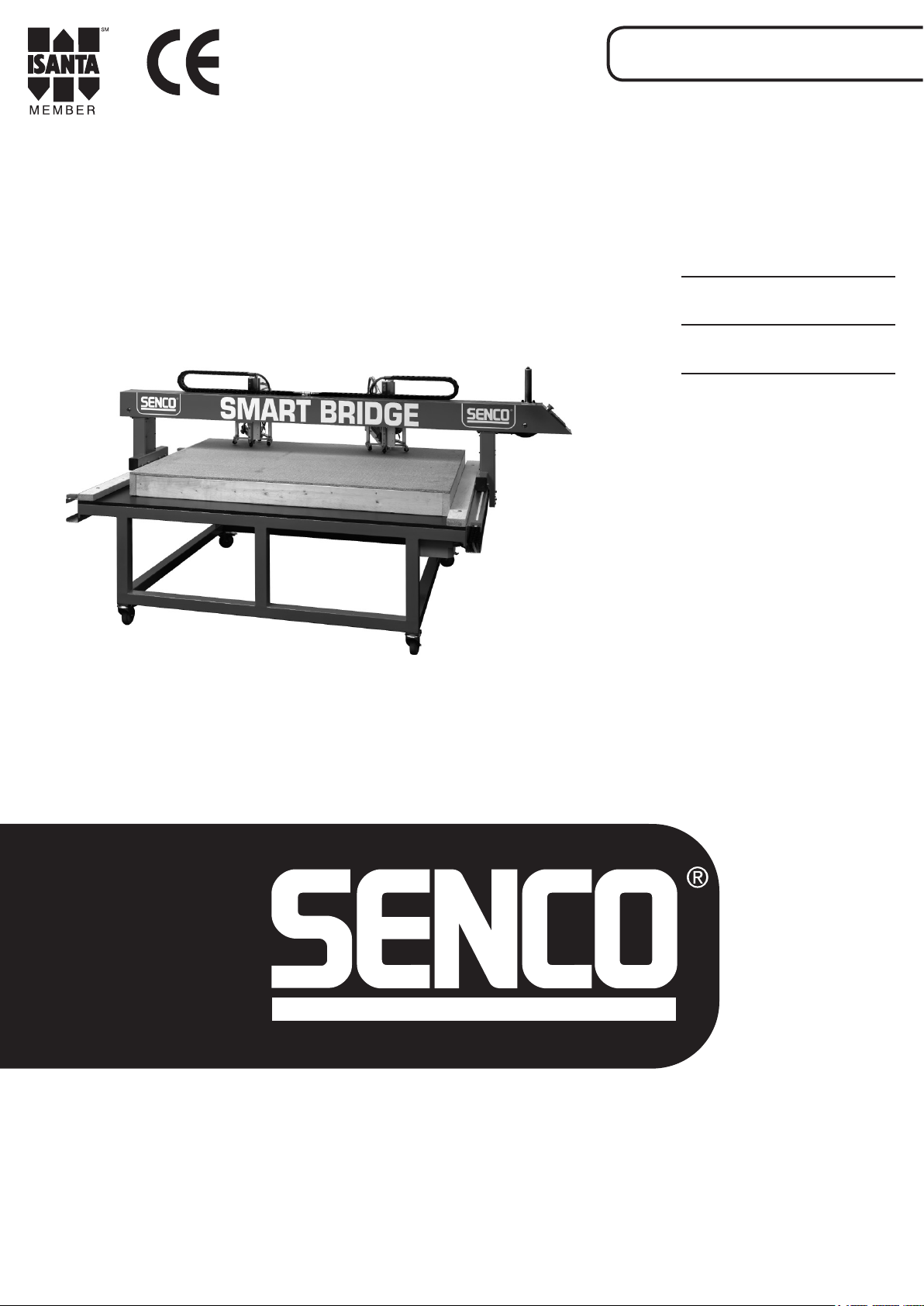
3. Purpose and function of the Smart Bridge
The purpose is to tack materials to each other with the ability to very quickly switch to another type of element
with another size.
The working conditions for the user are optimal:
• Since the tacking machines are installed on the Smart Bridge and are moved by the user by hand. The user no longer has
to climb onto the table. This simplies the work for the users (tacking, pressing and no requirement to lift).
• Since the tack distance can be set, you have a better and greater-looking product.
The quality of the product is partly determined by the quality and dimensional accuracy of the material to be processed.
PURPOSE AND FUNCTION OF THE SMART BRIDGE
Warnings
Warnings on the Smart Bridge must remain clearly legible. And, if necessary, be replaced.

5
GB
5
4 Safety
4.1 Symbols used
Danger
Ignoring this warning can result in injury.
Warning
Ignoring this warning can result in injury or severe damage to the device.
Caution
Ignoring this warning can result in minor damage to the device.
Info
Important information.
4.2 Safety rules
• The user has read and is fully familiar with the manual!
• Only fasteners from Senco are used. These are tested by Senco for these devices.
• The Smart Bridge receives the correct maintenance (see Maintenance chapter).
• The user and the employees who work on the Smart Bridge or in the vicinity wear safety glasses and the correct
hearing protection.
• Before a button is operated, the user must check that he can safely press this button.
• The operating pressure does not exceed 8 bar.
• The devices never tack 2 x in the same location (the tacks can ricochet off the tacks that are already present).
• The devices and sensors are rmly secured and correctly adjusted (see adjustments)!
• No people on the worktable.
• No objects may be placed on the Smart Bridge or table which the Smart Bridge has to pass over or that can
obstruct the passage of the Smart Bridge.
• You must ensure that the sheet material lies at so that it does not obstruct the passage of the tacking machines.
• If deviating cases are encountered, you must immediately inform Senco.
• Ensure that children do not have access to the installation.
• During maintenance, disconnect the compressed air.
• Only persons who have read and are fully familiar with operating instructions may operate the installation.
• Safety precautions may not be removed or rendered inoperative.
• Do not place anything on or underneath the installation.
• Ensure that there is sufcient ambient lighting.
• During the work, always ensure that 1 or more persons are present.
• The installation may not be put into use before all settings and adjustments have been properly made.
• Do not reach into the installation with your hands or with objects.
• In the event of malfunctions, service personnel must be deployed.
• Work may not take place without hearing protection.
• Nothing on the installation may be modied.
• Warning signs on the installation must remain clearly legible and, if necessary, renewed.
SAFETY

The maximum depth of the tack is a few tenths of a
millimetre below the surface. If this is adjusted too deep,
the tacker unit will „stick” and leave stripes behind on the
material!
6
GB
5 Operation
OPERATION
• Connect the main air to the Smart Bridge.
• Check for leaks and rectify these if necessary.
• Connect 220 volts to the terminal box:
➀Information is then displayed on the display of the control module.
➀If nothing is displayed, check that the red button is
pulled out.
• The devices then revert to pause mode.
• Place a workpiece on the table and move the Smart Bridge until it is
above the workpiece.
• ➀Switch on tacker units 1 and 2 by pressing tacker units 1 and 2
on the control module.
➀At the top left of the window, 12 appears (tacker unit 1 and 2
tacker unit 2).
For automatic height adjustment (optional):
Press button Y-. The devices move downwards.
• Pressing the red button jolts both devices.
5.1 Depth adjustment
• Check the depth of the tack in the material.
• The height of the tacker can be adjusted using 12 bolts:
Set the tacker slightly higher: the tack is inserted less deeply into the
material.
Set the tacker slightly lower: the tack is inserted deeper into the
material.
1
2
1
2

Automatic height adjustment
7
GB
5.2.1 Manual height adjustment
• Place the tacker unit on the product to be tacked. Unscrew nut ➀
until a clearance of 1-2 mm is obtained.
• The swivel wheels now rest on the product. During the tacking, the
tacker unit moves over the product. Since the swivel wheels follow
the product, every tack is the same depth. Due to this construction,
the tacker unit does not fall in when passing an opening.
5.2.2 Automatic height adjustment (optional)
• Y + = units upwards.
• Y - = units downwards.
1
1-2 mm

XY
X
Y
X
Y
1. Switch on tacker unit 1 and
2 on the control module
2. Turn the hand wheel to bring
tacker unit 2 to the correct
position
X
Y
3. Switch off tacker unit 2 on
the control module
X
Y
4. Move tacker unit 1 to the
correct position by turning
the hand wheel
1
2
2
2
1
1
2
1
1
2
If tacking is performed in the X-direction, then the
Y-direction is blocked and vice-versa!
8
GB
6.1 Switching tacker units on and off
• Using the buttons 1- 9, you can switch the desired tacker units on
and off. In this example, tacker unit 1 and tacker unit 2 are switched
on.
6.2 Moving tacker units into correct position for tacking in the
X-direction.
• Using button X/Y, you can adjust the tacking direction.
X= longitudinal direction Y= lateral direction.
• On the display, ensure that X is shown.
And move the bridge to the starting point.
6.3 Moving tacker units in the Y-direction
• By turning the hand wheel, the activated tacker units move in the
Y-direction.
6 Operation
OPERATION
• When the bridge is at the starting point, lock the bridge in the X
direction by pressing X/Y that a Y is shown on the display

1
2
1
Automatic height adjustment
9
GB
X-direction tacking
• When the tacker units are in the correct position, set the tacking
direction to X with button X/Y.
• Ensure that X is shown on the display and switch on both tacker
units.
6.4.1 Tacking distance in the X-direction for manual
height adjustment
• - X+ button increases tacking distance in X-direction in centimetres.
- X- button decreases tacking distance in X-direction in centimetres.
• in this case, for the X-direction, every 10 cm is displayed on the
screen.
6.4.2 Tacking distance in the X-direction for automatic height
adjustment (optional)
• - prog button (➀)and X+ (➀)increases tacking distance
in X-direction in centimetres.
- prog button (➀)and X- (➀)decreases tacking distance
in X-direction in centimetres.
• in this case, for the X-direction, every 10 cm is displayed on the
screen.
6.5 Tacking in X-direction
• - You can give a “tack” command with the red button.
- If you keep the red button pressed and the Smart Bridge moves in
the X-direction, the activated tacker units will make a tack at every
set value.

12
X
Y
X
Y
1
1. Switch off tacker unit 2 on
the control module.
2. Bring tacker unit 1 to the
middle of the workpiece.
X
Y
3. Switch on tacker units
1 and 2 on the control
module.
2
2
1
2
1
Automatic height adjustment
1
10
GB
Y-direction tacking
6.6 Positioning tacker units for tacking in the Y-direction
6.7.1 Tacking distance in the Y-direction for manual height
adjustment
• - button Y+ increases the tacking distance in Y-direction in
centimetres.
- button Y- decreases the tacking distance in Y-direction in
centimetres.
• in this case, for the Y-direction, every 10 cm is displayed on the
screen
6.7.2 Tacking distance in the Y-direction for automatic height
adjustment (optional)
• - prog button (➀)and Y+ (➀)increase the tacking distance
in the Y-direction in centimetres.
- prog button (➀)and Y- (➀)decrease the tacking distance
in the Y-direction in centimetres.
• in this case, for the Y-direction, every 10 cm is displayed on the
screen.

3
2
1
For automatic height adjustment (optional)
The tacker units can only move upwards when the
material sensor „detects” material.
The tackers can only tack when the material sensor
„detects” material and the sensor on the cylinder is lit
(yellow).
11
GB
Y-direction tacking
6.6 Positioning tacker units for tacking in the Y-direction
6.7.1 Tacking distance in the Y-direction for manual height
adjustment
• - button Y+ increases the tacking distance in Y-direction in
centimetres.
- button Y- decreases the tacking distance in Y-direction in
centimetres.
• in this case, for the Y-direction, every 10 cm is displayed on the
screen
6.7.2 Tacking distance in the Y-direction for automatic height
adjustment (optional)
• - prog button (➀)and Y+ (➀)increase the tacking distance
in the Y-direction in centimetres.
- prog button (➀)and Y- (➀)decrease the tacking distance
in the Y-direction in centimetres.
• in this case, for the Y-direction, every 10 cm is displayed on the
screen.
6.8 Tacking in Y-direction
• - With red button, you can give a “tack” command.
- If you keep the red button pressed, and turn the hand wheel on
the Smart Bridge, a tack will be placed in the Y-direction at each set
value.
• With the option button, you can display the number of processed
tacks.
7 Maintenance
MAINTENANCE
Daily:
• ➀Clean the rail system in longitudinal direction (X-direction).
If not cleaned, the toothed belts can become damaged.
• ➀Check that no debris is present underneath the energy chains.
This can cause damage to the cables and the energy chains.
• ➀Clean the guide in Y-direction using a dry cloth.
Spray the guide with silicon spray.
• Check that the tacker is rmly secured.
• Check that the air pressure is 7 bar.
• Check for leaks.

12
GB
8 Malfunctions
MALFUNCTIONS
DESCRIPTION CAUSE ACTION
No display No current Plug in power socket.
Emergency stop pressed. Pull out
emergency stop.
Remove 220-volt plug for 10 seconds
from the power socket. If, after swit-
ching on 220 volts, the display works,
then there is a short-circuit. Please
contact the supplier.
Tacker unit does not work Tack distance value on display is 0. Increase X or Y.
„Material sensor” does not detect any
material.
Check that sensor works. Hold a piece
of paper underneath the sensor, the
lamp on the sensor and the distribu-
tion block become lit. If the lamp is lit,
then the „sensor material” is possibly
too far away from the material.
No or insufcient compressed air Check compressed air (7 bar).
Tacker does not work This can be checked by disconnecting
the hose from the remote control. If
air comes out of the hose when the
tacker is operated, the tacker must be
repaired.
Magazine empty Fill magazine.
Controls do not work Please contact the supplier.
Tacker unit leaves stripes behind on
the material
Depth adjustment incorrect Please contact TD.
Smart Bridge does not work
perpendicular (deviation more than
10 mm).
Incorrect adjustment of belts Please contact TD.

13
GB
9 Technical data
Dimensions
Length:
Width:
Height:
Weight: < 500 kg.
Noise: >100 dB(A)
Type of machine:
Pneumatic
Compressed air: 7 bar
Consumption: 2 litres/ tacking
Physical conditions of use
Ambient temperature:
- Operating: + 5 to + 40°C.
- During transport: - 25 to + 55°C.
- Relative humidity: 30 % to 90 % (RH) non-condensing
Applied directives:
This installation is provided with a CE-marking. This means that this installation complies with the applicable European
directives relating to safety and health. These directives are stated in the "Declaration of conformity". The applied
standards are also stated in the "Declaration of conformity".
TECHNICAL DATA

14
GB
10.1 Smart Bridge total
14
PARTS OF SMART BRIDGE
10 Parts of Smart Bridge
Position Description Order number
1 Tacker unit -
2 Knob with cable VSP-00278
3 Control module VSP-00279
4 X-drive
5 Y-drive
6Regulator - lter VSP-00280
7 24 volt power suply VSP-00281
/

15
GB
15
10.2 Smart Bridge tacking waggon
Position Description Order number
1.1 Distribution system VSP-00282
1.2 Cable 5 meter male straight female 90
12-pol.
VSP-00283
1.3 Cable 30 cm. Male 90 female 90 VSP-00284
1.4 Pneumatic valve 3/2 3/2 VSP-00285
1.5 pushin connector M7- 4mm 90 VSP-00286
1.6 Sensor 30 mm VSP-00287
1.7 cable special cable male 90 female
straight m8 30cm
VSP-00288
1.8 swiffel wheel VSP-00289
1.9 Guidance assembly VSP-00290
1.9.1 pushin connector throttle valve VSP-00291
1.9.2 Cilinder VSP-00292
1.9.3 pushin connector throttle valve VSP-00291
1.9.4 pushin connector VSP-00293
1.9.5 Brake VSP-00294
1.9.6 cable special cable male 90 female
straight m8 60cm
VSP-00295
1.9.7 Sensor VSP-00296

16
GB
10.3 Smart Bridge X-drive
Position Description Order number
4.1 Sensor with special cable male 90
female straight m8 30cm
VSP-00297
4.2 Cable 30 cm. Male 90 female 90 VSP-00298
4.3 Pneumatic valve 3/2 3/2 VSP-00299
4.4 pushin connector M7- 4mm 90 VSP-00300
4.5 Distribution system VSP-00282
4.6 Rail VSP-00301
4.7 Brake with pushin connector VSP-00302
4.8 Set X-quiding VSP-00303
4.9 Energy chain part VSP-00304
4.10 Energy chain connection set VSP-00305
4.11 Set parts wheel X-direction VSP-00306
4.12 Set parts toot belt wheel VSP-00307
4.13 Tooth belt VSP-00308
4.14 Ball bearing VSP-00309
4.15 Plain Bearing VSP-00310

17
GB
10.4 Smart Bridge X-drive
Position Description Order number
5.1 Guideway + length VSP-00311
5.2 Cable 5 meter male straight female 90
12-pol.
VSP-00312
5.3 Distribution system VSP-00282
5.4 Energy chain connection set VSP-00305
5.5 Energy chain part VSP-00304
5.6 Plain Bearing VSP-00313
5.7 Sensor with special cable male 90
female straight m8 30cm
VSP-00314
5.8 Brake with pushin connector VSP-00302
5.9 Block guideway VSP-00315
5.10 Tooth Belt + length VSP-00316
5.11 Block guideway VSP-00317
5.12 Guideway-Y + length VSP-00318

10.5 5 Smart Bridge handle
18
GB
18
Position Description Order number
2.1 Switch + cable VSP-00278

19
NL
INHOUDSOPGAVE
1 Voorwoord 20
2 Inleiding 20
2.1 Gebruikers 20
3 Doel en functie van de Smart Bridge 20
4 Veiligheid 21
4.1 Gebruikte symbolen 21
4.2 Veiligheidsregels 21
5 Werking 22
5.1 Diepte-instelling 22
5.2.1 Handmatige hoogte-instelling 23
5.2.2 Automatische hoogte-instelling (optioneel) 23
6 Bediening 24
6.1 Hechtunits in- en uitschakelen 24
6.2 Hechtunits in juiste positie brengen voor hechten in de X-richting. 24
6.3 Verplaatsen hechtunits in de Y-richting 24
6.4.1 Hecht-afstand in de X-richting bij handmatige hoogte-instelling 25
6.4.2 Hecht-afstand in de X-richting bij automatische hoogte-instelling (optioneel) 25
6.5 Hechten over X-richting 25
6.6 Positioneren hechtunits voor hechten in de Y-richting 26
6.7.1 Hecht-afstand in de Y-richting bij handmatige hoogte-instelling 26
6.7.2 Hecht-afstand in de Y-richting bij automatische hoogte-instelling (optioneel) 26
6.8 Hechten over Y-richting 27
7 Onderhoud 27
8 Storingen 28
9 Technische data 29
10 Onderdelen Smart Bridge 30
10.1 Smart Bridge totaal 30
10.2 Smart Bridge hechtwagen 31
10.3 Smart Bridge X-drive 32
10.4 Smart Bridge Y-drive 33
10.5 Smart Bridge X-drive 34
Garantie 35
EG Verklaring van overeenstemming 36
Lees eerst zorgvuldig deze handleiding en de handleiding van de geïnstalleerde tool alvorens met de
machine te werken!

20
NL
20
1 Voorwoord
Deze documentatie is een handleiding en beschrijft de mechanische aspecten van de Smart Bridge.
Deze documentatie is onderdeel van de Smart Bridge. Bij overdracht van de installatie dient de documentatie
meegeleverd te worden.
Bewaar deze documentatie zorgvuldig; er staat informatie in, die ook later van pas komt of nodig is voor bijvoorbeeld
reparatie of onderhoud.
Werkzaamheden die uitgevoerd dienen te worden door personeel van Senco zijn niet in deze documentatie opgenomen.
Het gebruiken van deze documentatie.
De instructies zijn ingedeeld naar de soort gebruiker van de installatie.
De volgende benamingen worden gebruikt:
Gebruiker
Dit is de dagelijkse gebruiker van de installatie.
Servicepersoneel
Personen met opleiding, ervaring en hulpmiddelen die vereist zijn voor de beschreven werkzaamheden.
Veiligheidsfunctionaris
Diegene die verantwoordelijk is voor de arbeidsomstandigheden in het bedrijf van de gebruiker. Indien er niemand voor
aangewezen is zal dit de werkgever zelf zijn.
Werkzaamheden die niet in deze documentatie zijn opgenomen dienen uitgevoerd te worden door personeel van Senco.
VOORWOORD
INLEIDING
2 Inleiding
Deze installatie is zodanig ontworpen en gebouwd dat deze veilig onderhouden en gebruikt kan worden. Dit geldt voor de
toepassing, de omstandigheden en de voorschriften, zoals in deze documentatie omschreven. Het lezen en volgen van
deze documentatie en het opvolgen van de instructies zijn dus noodzakelijk voor iedereen die met of aan deze installatie
werkt. Bij professioneel gebruik is het de verantwoordelijkheid van de veiligheidsfunctionaris of werkgever dat deze
instructies bekend zijn en nageleefd worden.
Er wordt in deze documentatie onderscheid gemaakt tussen normaal gebruik en overige werkzaamheden. De reden
hiervan is dat er, vooral met het oog op veiligheid, aan het servicepersoneel andere eisen worden gesteld dan aan
gebruikers.
De afstellingen en of instellingen moeten door terzake deskundig servicepersoneel worden uitgevoerd.
2.1 Gebruikers
De installatie kan worden bediend door elk volwassen persoon, die de inhoud van veiligheid en bedieningsvoorschriften
kent en opvolgt. De veiligheidsfunctionaris controleert of de gebruiker in staat is en voldoende kennis heeft om met de
installatie te werken.
3. Doel en functie van de Smart Bridge
Het doel is materialen op elkaar te hechten met de mogelijkheid zeer snel om te schakelen naar een ander type element
met een andere maatvoering.
De werkomstandigheden voor de gebruiker zijn optimaal:
• Doordat de hechtmachines zijn ingebouwd op de Smart Bridge en handmatig worden bewogen door de gebruiker. De
gebruiker hoeft niet meer op de tafel te klimmen. Dit zorgt voor een arbeids-vriendelijker werken. (Hechten, aandrukken
en niet hoeven tillen)
• Omdat de spijkerafstand kan worden ingesteld, heeft men beter en mooier product.
De kwaliteit van het product wordt mede bepaald door de kwaliteit en maatnauwkeurigheid van het te verwerken
materiaal.
DOEL EN FUNCTIE VAN DE SMART BRIDGE
Waarschuwingen
Waarschuwingen op de Smart Bridge moeten duidelijk leesbaar blijven. En indien nodig worden
vernieuwd.
Table of contents
Languages:
Other Senco Industrial Equipment manuals