Sencon 387-WR User manual

387-WR BODYMAKER SENSOR SYSTEM
INSTRUCTION MANUAL
RELEASE 1.1

© 1993, 1996 Sencon Incorporated Page 1 387-WR Bodymaker Sensor System
DESCRIPTION
ALUMINUM-ON-PUNCH BODYMAKER SENSOR SYSTEM
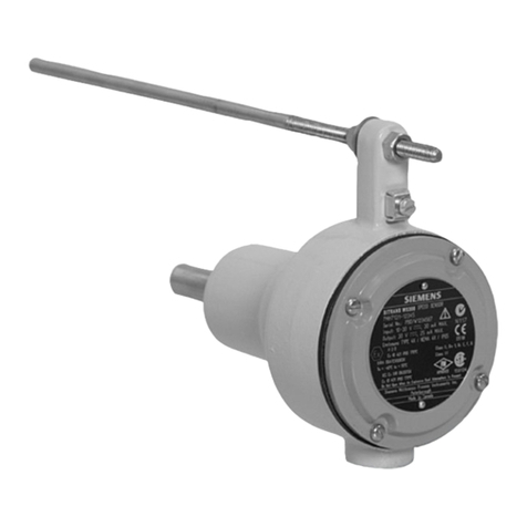
T e Aluminum-on-Punc Bodymaker Sensor System detects t e presence of wall-ironed aluminum on t e
forming punc of a bodymaker. T e system is made up of a specialty sensor, t e 387-S1, and a control
module, t e BCM387-WR. T e system automatically compensates for t e magnetic properties of t e punc
and mounting ardware, eliminating t e need for a different sensor for eac punc composition. T is also
eliminates problems associated wit magnetic variations attributed to carbide batc tolerances and minimizes
t e effect of variations due to temperature. T e system profiles t e punc , w ic allows t e sensor to detect
tearoffs and s ort cans accurately before t e punc fully extends, t us providing more time to stop t e
mac ine. T e Sensor System detects aluminum over a variety of punc materials, including ceramic punc es
t at ave steel nose pieces. T is makes it ideal for plants c anging from one punc type to anot er.
T e Bodymaker Sensor System offers an immediate stop mode. In t is mode, t e module immediately opens
two transistor switc es t at can interrupt 2 Amperes at 24 Volts w en it detects a defect. A sync ronized stop
can be done t roug t e mac ine PLC logic by monitoring t e sensor output signal.
T e calibration of t e sensor requires some c anges in t e mac ine control logic. T is tunes t e sensor to
t e punc material and profile. T e system needs t ree or more dry strokes (mac ine strokes wit out cans in
process) to calibrate t e sensor. T e sensor maintains calibration information internally in EEPROM,
eliminating t e need to recalibrate every time t e power to t e sensor cycles. T e system needs recalibration
w enever any of t e following conditions appen:
1. t e sensor is c anged;
2. t e sensor to punc gap is c anged;
3. t e punc is rotated;
4. t e punc is c anged;
5. or t e timing window is c anged.
T e 9H-387-S1 sensor as an integral cable and t e 11H-387-S1 sensor is terminated using a quick
disconnect cable. A ose fitting designed to accept 0.75" I.D. [19.1 mm] ydraulic tubing surrounds t e
connector. Use a stainless steel ose clamp to provide a positive mec anical and ydraulic seal of t e ose
to t e fitting. T is aids in s ielding t e sensor and connector from t e bodymaker coolant.

© 1993, 1996 Sencon Incorporated Page 2 387-WR Bodymaker Sensor System
DIMENSIONS
9H-387-56 Sen or
11H-387-S1 Sen or
BCM387-WR Module

© 1993, 1996 Sencon Incorporated Page 3 387-WR Bodymaker Sensor System
SPECIFICATIONS
Input Supply Voltage
Module
24 VDC ±2.4 VDC
Input Supply Current
Module
400 mA Plus Load Current at 24 VDC
Module
Signal Inputs
Configuration
Sour e or Sink (Set with Jumper)
A tive High or A tive Low (Set with Jumper)
Voltage
Range
Minimum
-0.7 VDC
Maximum
Input Supply Voltage Value
Threshold
High State
55% of Input Supply Voltage
Low State
45% of Input Supply Voltage
Impedan e
5 kΩ
Allowable Leakage
400 µA
Reverse Polarity
Sensor
Prote ted
Case Isolation
Sensor
200 VDC
Storage Temperature
Module
+ 40° F to +185° F [+ 4° C to +85° C]
Sensor
+ 40° F to +185° F [+ 4° C to +85° C]
Operating Temperature
Module
+32° F to +158° F [0° C to +70° C]
Sensor
+32° F to +158° F [0° C to +70° C]
Environment
Module
IP20 - Requires mounting in an IP65 or NEMA 12 en losure.
Sensor
IP65 or NEMA13 when installed with a hydrauli hose and
stainless steel lamp.
GENERAL CHARACTERISTICS
Weight
Module
1 lb [450 g]
Sensor
5 oz. [140 g]
Case
Module
Poly arbonate
Sensor
Stainless Steel
Termination
Module
S rew terminals re essed to prote t against a idental onta t.
11H-387-S1 Sensor
Qui k Dis onne t with Hose Fitting - Use ONLY the mating onne tor
available through Sen on. Other onne tors whi h appear to be
equivalent may not be ompatible. Refer to Te hni al Data Sheet #
096-00007-xx (Cables for DC Sensors).
9H-387-S1 Sensor
10' [3 m] Cable with Hose Fitting
SENSOR OPERATING CHARACTERISTICS (RANGE TO TARGET)
Pun h Material
Aluminum on Carbide
Pun h (Ni kel Binder)
Aluminum on
Steel Pun h
Aluminum on
Cerami Pun h
Aluminum on Carbide
Pun h (Cobalt Binder)
Sensing Range
0.065" to 0.100"
[1.7 to 2.5 mm]
0.065" to 0.300"
[1.7 to 7.6 mm]
0.150" to 0.250"
[3.8 to 6.4 mm]
0.065" to 0.180"
[1.7 to 4.6 mm]
Setting Distan e
0.080" [2.0 mm]
0.205" [5.2 mm]
0.200" [5.1 mm]
0.120" [3.0 mm]

© 1993, 1996 Sencon Incorporated Page 4 387-WR Bodymaker Sensor System
MODULE SOLID STATE SWITCH OUTPUT CHARACTERISTICS
Maximum Load
40 mA, Typi al ON resistan e at 25 mA is 25 Ω
500 mW maximum power through the swit h
Voltage Range
0 to 50 VAC (peak) or 0 to 50 VDC
Leakage Current
< 1 mi roamp
Output Type
Bi-dire tional, opti ally isolated solid state swit hes.
Output Configuration
Suitable for DC sour e, DC sink, or AC.
Output State
Calibration
ON when Sensor Calibrated to Pun h
Sensor
Output
ON
(Good Can)
Normal output state when no defe t is dete ted or during
alibration.
OFF
(Reje t)
Full an Mode - Signal is present from the time the defe t is
dete ted until 70 ms following the trailing edge of the window
signal.
Trimline Mode - Signal is present approximately 2 ms after the
end of the window signal until 70 ms following the trailing edge of
the window signal.
Sensor
Output 2
ON
(Good Can)
Normal output state when no defe t is dete ted or during
alibration.
OFF
(Reje t)
Signal refle ts the a tual state of the sensor. Is useful in
determining the point along the pun h where the defe t is first
dete ted.
MODULE TRANSISTOR SWITCH OUTPUT CHARACTERISTICS
Maximum Load
2 A DC Resistive/Indu tive
Voltage Range
-0.7 VDC to 30 VDC
Voltage Drop
0.6 VDC at 1 A, 0.9 VDC at 2 A
Short Cir uit Prote tion
Momentary (10 se onds)
Output State
Determined by the operating state. Refer to the `Operation' se tion of this TDS for
details.
Output Configuration
Opti ally Isolated FET Transistor Swit h, Condu tive in the A tive State

© 1993, 1996 Sencon Incorporated Page 5 387-WR Bodymaker Sensor System
INSTALLATION
MECHANICAL INSTALLATION
BCM387-WR Module Mounting
T e BCM387-WR controller mounts in a control
cabinet, protected from moisture and ydraulic
fluids. Mount t e unit on a 35-mm DIN rail or wit
two fasteners. Recommended screw fasteners
are #8 or M4.
387 Sen or Mounting
Securely mount t e sensor as s own in t e
diagrams. Use t e table below for t e proper
setting distance between t e sensor and t e
punc . T e centerline of t e sensor must be
perpendicular to t e centerline of t e punc
and must pass t roug t e center of t e punc .
Make sure to seat fully and tig ten t e cable
connector on t e 11H-387 sensor. Also install
and clamp t e ydraulic tubing over t e fitting.
Pun h Material
Aluminum on Carbide
Pun h (Ni kel Binder)
Aluminum on
Steel Pun h
Aluminum on
Cerami Pun h
Aluminum on Carbide
Pun h (Cobalt Binder)
Setting Distan e
0.080" [2.0 mm]
0.205" [5.2 mm]
0.200" [5.1 mm]
0.120" [3.0 mm]

© 1993, 1996 Sencon Incorporated Page 6 387-WR Bodymaker Sensor System
ELECTRICAL INSTALLATION
T e inputs and outputs to t e BCM387-WR are s own ere. Electrical connection is made to t e unit wit
screw terminals. T e terminals are recessed to reduce t e c ances of accidentally contacting t em.
387 Sen or Interconnection
Make sure to seat fully and tig ten t e cable connector on t e 11H-387 sensor. Also install and clamp t e
ydraulic tubing over t e fitting. Ot erwise, liquid may infiltrate t e connector and degrade performance.
(Black)
(Green)
(Yellow)
(White)
(Blue) NC
(Red/Black)
(Green)
(Red/Yellow)
(Red/White)
9H 387
Sen or
11H- 387
Sen or

© 1993, 1996 Sencon Incorporated Page 7 387-WR Bodymaker Sensor System
DC Signal Input
Configure t e input signals as s own in t e diagram below. Settings are made wit minijumpers accessible
under t e top cover of t e unit. Remove t e top cover by inserting a flat screwdriver blade in t e slot s own
and rotating t e blade to `pop' t e cover off. T is operation MUST be done wit power off to avoid damaging
t e unit.
If an input is active ig , t e presence of a voltage above t e t res old at t e input terminal is ON, and voltage
below t e t res old at t e terminal is OFF. T e reverse is true if an input is active low. T e transition from
OFF to ON is t e leading edge of t e signal. T e transition from ON to OFF is t e trailing edge of t e signal

© 1993, 1996 Sencon Incorporated Page 8 387-WR Bodymaker Sensor System
Solid State Switch Output
T ese outputs are optically isolated from t e supply voltage w en t e jumper is set to ‘Output Common’.
T erefore, t e COM terminal is floating and can be connected to any reference t at falls wit in t e specified
voltage range. Connect not ing to t e COM terminal if t e jumper is set to ‘Output Current Source’ or to
‘Output Current Sink’.
FET Tran i tor Switch Output
T e system as t ree FET transistor switc es for
control of t e bodymaker clutc /brake solenoids and
t e dump valve. T e contacts are FET transistors
t at are optically isolated from t e internal power
supply.
IMPORTANT SAFETY NOTICE - The tran i tor
witche provided with thi unit mu t not be the
only mean of controlling the bodymaker clutch
mechani m. Good de ign practice dictate the
u e of afety lockout on any device that tart
and top automatically that can cau e per onal
injury to operating or maintenance per onnel.
The BCM387-WR mu t be u ed only with indu try
approved afety lockout contact , otherwi e
eriou per onal injury may re ult.

© 1993, 1996 Sencon Incorporated Page 9 387-WR Bodymaker Sensor System
OPERATION
MODULE SIGNAL INPUTS
T e Bodymaker Sensor System requires t e five inputs described ere. T ese inputs are not optically
isolated from t e BCM387-WR internal power supply.
Input
Description
Calibrate
T e Calibrate input sends a calibrate command to t e sensor. W en t e module
detects a good calibration, t e Good Calibration output turns ON. T is takes at least
t ree cycles. T e Calibrate input must be OFF before t e cup feed turns on.
Window
T e Window signal is active w en t e punc is in position for sensing. T e trailing
edge of t e window signal corresponds to t e can body trimline.
Mode Select 1
and
Mode Select 2
T e state of t ese inputs sets t e mode of t e BCM387 Module.
Trimline/
Fullcan
T e system does a Fullcan c eck w en t is input is OFF. For a Fullcan c eck, t e
sensor profiles t e punc and evaluates t e can at various points along t e punc .
T e system does a Trimline c eck w en t is input is ON. For Trimline c eck, t e
system only evaluates t e trimline of t e can.
SOLID STATE SWITCH LOGIC OUTPUTS
T e Bodymaker Control Module as t ree solid state switc outputs. T ese outputs are bidirectional and
isolated from t e BCM387-WR internal power supply if t e appropriate jumper is set to t e ‘Output Common’
position. T e outputs can be wired for DC source, DC sink, and AC. T ey are rated for 40 mA (maximum) at
up to 50 VAC (peak) or 50 VDC.
Output
Description
Good
Calibration
T e Good Calibration output is ON (current flow allowed) after t e sensor as been
calibrated and remains ON w ile t e sensor calibration is good.
Sensor Output
and Sensor
Output 2
T e Sensor Output and Sensor Output 2 s ow s ort cans and tearoffs. T ey also
pulse once eac mac ine cycle to s ow t e system is functioning (backstop c eck).
See t e timing diagrams for details.
Note: If t e sensor fails, t e backstop c eck will not occur.

© 1993, 1996 Sencon Incorporated Page 10 387-WR Bodymaker Sensor System
TRANSISTOR SWITCH CLUTCH/SOLENOID CONTROL OUTPUTS
T e driver outputs are FET transistor switc es and are isolated from t e supply power. T e rated load is two
amperes maximum at 30 volts. Observe t e proper polarity.
Output
Mode
Description
Clutc 1,
Clutc 2, and
Dump Valve
Transistor Switc es Held Open
T e outputs are always open.
Transistor Switc es Held Closed
T e outputs are always closed.
Immediate Mode
T e outputs are closed w ile t ere are no faults.
T ey remain closed until a fault occurs. W en a
fault occurs, t e outputs open immediately and
remains open 70 milliseconds after t e end of
t e Window signal.
OPERATIONAL MODE SELECTION
T e operational mode is set wit t e state of t e Mode Select 1 and Mode Select 2 inputs. T is table s ows
t e t ree modes.
Mode Select 1
Mode Select 2
Mode
Comment
Off
Off
Transistor Switc es Held Open
T e transistor switc es are
always open.
On
On
Transistor Switc es Held
Closed
T e transistor switc es are
always closed.
On
Off
Immediate Mode
T e transistor switc es follow t e
sensor error signal.
FULLCAN CHECK AND TRIMLINE CHECK
T e system normally does a full can c eck w en it is evaluating a can for defects. T e sensor evaluates t e
punc at various points during t e window. Trimline c eck differs from t is in t at t e system only evaluates
t e trimline. T e system can be forced into trimline c eck wit t e Trimline/Fullcan input. T e system goes
into trimline c eck w en t e signal is applied, and will remain in t is mode until t e signal as been removed.

© 1993, 1996 Sencon Incorporated Page 11 387-WR Bodymaker Sensor System
WINDOW AND CALIBRATE SIGNAL TIMING
T e diagram below describes t e relations ip between t e Window signal, t e Calibrate signal, and t e
position of t e punc . T e Window signal becomes active sometime after t e nosepiece of t e punc as
passed t e sensor, and remains active until t e trimline is reac ed. T e Calibrate signal must be active a
minimum of 20 milliseconds before t e leading edge of t e Window signal.
Parameter
Symbo
l
Limits (Degrees of Travel)
Dome Offset
d
DOME
Approximately 0.5" [13 mm]
(from the end of the pun h to the enterline of the sensor)
Setup Time
t
SU
20 mse . (minimum)
Window Time
t
WINDO
W
3.5 mse . (minimum) to
50 mse . (maximum)
T e maximum allowable variation in t e Window time (t
WINDOW
) between successive mac ine strokes is ±20%.
Make sure not to exceed t is limit w en t e mac ine accelerates or decelerates from one speed setting to
anot er. If t e t
WINDOW
time c anges by more t an ±20% between successive mac ine strokes, t e system
may not detect a tear off until t e trimline c eck is made.

© 1993, 1996 Sencon Incorporated Page 12 387-WR Bodymaker Sensor System
REJECT AND BACKSTOP CHECK TIMING
T e system provides a signal s owing t at it is working properly, commonly called t e backstop c eck. T e
Sensor output will turn off 35 milliseconds after t e trailing edge of t e Window and will remain off for 35
milliseconds. T is does not indicate t e detection of a defect, but s ows t at t e system is operating properly.
T e system s ows a defect w en t e Sensor output turns off w ile t e Window signal is on, or turns on wit in
2 milliseconds after t e trailing edge of t e Window signal. T e Sensor output stays on until 70 milliseconds
after t e trailing edge of t e Window signal.
T e Sensor Output 2 follows t e state of t e 387 sensor, no matter if t e BCM387 is in Trimline or Fullcan
mode. T is is useful in determining w ere t e defect was first detected w en t e system is in Trimline mode.
T e Sensor Output 2 does not latc . If t e system detects a tear off at an intermediate point along t e punc
t at turns out to be invalid, t is output toggles off momentarily and t en back on.

© 1993, 1996 Sencon Incorporated Page 13 387-WR Bodymaker Sensor System
CALIBRATION
T e 387-S1 sensor must be calibrated to t e punc before operation. If t e first two digits of t e sensor serial
number are ‘71' or ig er, t en t e sensor saves t e calibration information in non-volatile EEPROM. A
Calibrate signal from t e sensor 100 milliseconds after power up s ows t e sensor as calibration information
stored in EEPROM. Earlier model sensors do not save calibration information and need calibration every time
t ey ave power applied to t em.
T e calibration is done by cycling t e mac ine at least t ree times wit t e Calibrate input on and wit out cans
in process. T ese cycles allow t e sensor to calibrate to t e punc material and to profile t e punc wit in t e
timing window. Subsequent starting and stopping of t e mac ine will not affect t e calibration.
T e Good Calibration output will turn on once t e sensor as successfully calibrated itself to t e punc . T is
signal will remain on w ile cans are in process. T e Calibrate input must go inactive after t e Good
Calibration output turns on and before t e cup feed turns on. Recalibration can be done by periodically
interrupting t e cup feed and setting t e Calibrate input.
TRANSISTOR SWITCHES HELD CLOSED
Use t is mode to stop t e bodymaker sync ronous to mac ine timing. T e transistor switc es are eld
closed. T e state of t e Sensor output can allow t e PLC to execute a normal stop sync ronized wit t e
backstop logic. T e action required to stop t e bodymaker must be done in t e PLC.

© 1993, 1996 Sencon Incorporated Page 14 387-WR Bodymaker Sensor System
IMMEDIATE STOP MODE
Use t e immediate stop mode to stop t e bodymaker async ronous to t e mac ine timing markers (t at is, as
fast as possible). T e transistor switc es will open w en t e system detects t e defect, allowing an immediate
stop to occur. T e switc es are guaranteed to be open only 70 milliseconds, so furt er action in t e PLC is
required to keep t e mac ine from restarting. T e state of t e Sensor output indicates to t e PLC t at a
defect as occurred.
TRANSISTOR SWITCHES HELD OPEN
T e transistor switc es will remain open, interrupting t e flow of current to t e solenoid coils. T e mode of t e
BCM module can be c anged during t e backstop c eck. T erefore, if t e system stops in immediate mode,
t e module can be switc ed to t is mode to keep t e switc es open.

© 1993, 1996 Sencon Incorporated Page 15 387-WR Bodymaker Sensor System
MAINTENANCE
T e system needs no periodic maintenance. However, t ere are some procedures to follow w en replacing
t e sensor or t e punc .
INSTALLING A REPLACEMENT 387 SENSOR
Install a replacement 387 sensor as s own on page 5 of t is manual. Make sure to seat t e connector fully
and to clamp t e ose securely. T ere are two special considerations to make w en replacing a sensor.
1. T e replacement sensor MUST be wired wit no power to t e module. T is ensures t at t e sensor
and module communicate properly.
2. T e sensor MUST be recalibrated once power is applied. Alt oug a newer style sensor wit t e
calibration information stored in EEPROM may s ow t at it is calibrated, it must be recalibrated to t e
punc on t e bodymaker.
INSTALLING A REPLACEMENT PUNCH
After installing a replacement punc , make sure to remount t e sensor as s own on page 5 of t is manual.
T e sensor MUST be recalibrated to t e replacement punc for proper operation.
SENSOR CALIBRATION
Sensor calibration MUST be done w enever any of t e following conditions appen:
1. t e sensor is c anged;
2. t e sensor to punc gap is c anged;
3. t e punc is rotated;
4. t e punc is c anged;
5. or t e timing window is c anged.
T e calibration procedure is described on page 13 of t is manual.

ORDERING INFORMATION: For price quotes or applications information, contact t e SENCON
sales office listed below:
SENCON INCORPORATED (Nort /Central/Sout America)
6385 West 74t Street, Bedford Park, IL 60638 USA
PHONE: +1-708-496-3100 FAX: +1-708-496-3105
SENCON (UK) LTD. (Europe/Middle East/Asia)
Stonebridge Cross Business Park
Droitwic WR9 0LW
UK
Tel: +44 1905 827800
Fax: +44 1905 795876
www.sencon.com
PUBLISHED 21 March 2006 16 TECHNICAL DATA SHEET# 096-38702-03
Please Note: Due to product improvement, specifications are subject to c ange wit out notice.
This manual suits for next models
1
Table of contents
