SENDER RAMPS CORE 200 User manual
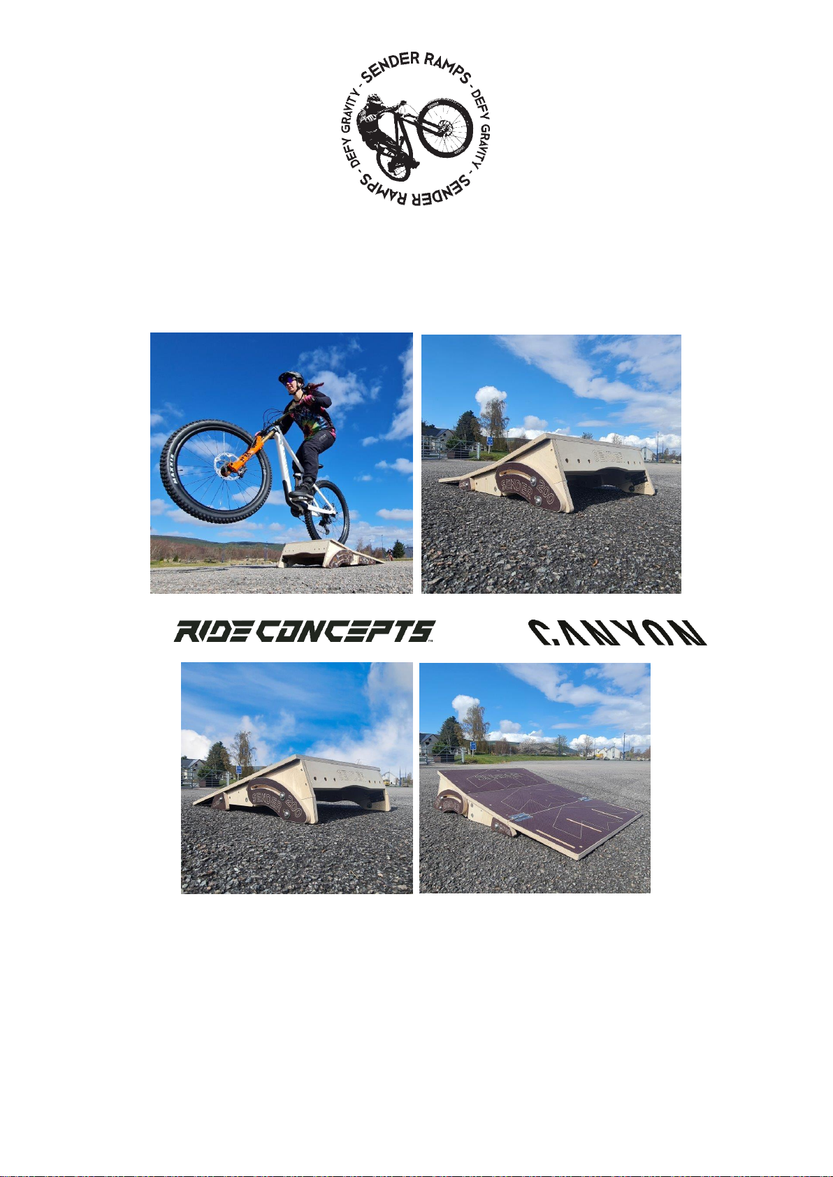
SENDER CORE RAMPS
CORE 200 STRAIGHT AND CURVED
FOOTWEAR: VICE - BIKE: STRIVE
PLEASE TAKE CARE OPENING YOUR PROGRESSION RAMPS WITH A KNIFE
THE OPTIONAL CARRY BAG MAY BE INSIDE ALONG WITH ASSEMBLY COMPONENTS.
Thank you for buying a SENDER CORE RANGE RAMP. They are part of our extensive, compact and transportable modular system.
Each part has been carefully considered for weight and strength. They are durable and built to last. Core Ramps are fixed in
height and angle. You can grow your range to progress and build confidence on Straight and Curved Transitions. Happy Landings.
MODULAR:
Our ramps integrate with other SENDER BOLT ON features. For advice on compatibility please contact us. Core ramps can be
used as a take-off and landing ramps in Straight or Curved mode.

TERRAIN ADJUSTMENT:
Core ramps are best used on grass but can be used on tar or concrete. However, the severity of landing and risk factor will
greatly increase on hard surfaces. There is a small amount of terrain adjustment in the rear legs to level your ramp.
SAFETY FEATURE:
The front edge of the ramp has 2 x PEG POINTS so you can add extra security when using the ramp on grass or gravel. We
recommend using these point to help prevent movement and fully stabilise the ramp.
SUITABLE FOR SKATEBOARDS and SCOOTERS
Progression ramps can be used with Skateboards and Scooters with the OPTIONAL Skate Plate. This Galvanised plate can be
retro fitted. Once installed it can be adjusted and placed in transport / storage mode
RAMP WEIGHT / RANGE / ADJUSTMENT + MARKINGS:
WEIGHT 12 Kgs CORE RANGE 200 mm HIGH –Fixed at 200 mm HIGH with 15 mm Terrain Adjustment
Transition Length CORE 200 STRAIGHT and CURVED Ramps is 900 mm
OPTIONAL COMPONENTS: TRANSPORT BAG –SKATE PLATE –PROGRESSION BOOSTER EXTENSION
The SENDER EXTEDER must NEVER be used on the 200 CORE STRAIGHT and CURVED as it will tip over.
SAFE OPERATION!
Once you are familiar with all the parts you can set up, fold and pack CORE RAMPS in 5 –10 minutes. You can easily adjust the
ramp to Compact Storage mode in a few minutes. YOU MUST ALWAYS check the components are bolted tightly together to
prevent the ramp from failing / folding or collapsing. Please lift your ramp into place with two people. Dragging the ramp will
damage components.
The Ramps have an OPTIONAL and strong Vinyl Carry Bag which has webbing strap points on the front you can use for attaching
clothing (you will need to add elastic or similar). Lift the bag using the central lifting loop or both handles to mount on your back.
The load / weight on one strap alone may rip the stitching. We do not recommend children under 16 carry the bag on the back
OR set the ramp up.
WARNING –These ramps have moving components that can cause a finger entrapment. Under 16’s should be supervised
when assembling, erecting or changing the mode of the ramp.
The Ramp has many MOVING PARTS which means finger entrapment is a significant risk. Always unfold / adjust / store with
care. Once again under 16’s should not set the ramp up. We advise packing, unpacking and transporting the ramp with two
people to avoid manual handling injuries.
DESIGNED FOR:
Riders, clubs and coaches on all types of bikes - Heavy use including E Bikes.
Safe Working Load is 150 Kgs –Dynamically Tested to over 350 Kgs
Bolt Torque setting is 12 Nm
SAFE USE AND PPE:
Always wear a full face helmet, gloves and knee pads when jumping. We also recommend back protection and a neck brace. You
should not jump ramp to ramp with a gap between components. Progression Ramps can be landed to FLAT. However, it is better
to use a grass downslope as the height increases or a landing ramp. Ensure adequate fall space all around with no surrounding
impact surfaces like fences, trees, vehicles or roads. Keep spectators clear. Locate your ramp on flat even ground. Take your
time and follow all the user instructions carefully for max strength. Built confidence before trying higher jumps. We recommend
hiring / consulting a coach to improve skills. When jumping goes wrong it can lead to life changing injuries and destroy expensive
bikes.
SENDER BUILT TO LAST:
Designed and Manufactured in the Highlands of Scotland from 18 mm (13 layer) Birch Plywood and 18 mm (13 layer) Phenolic
Grip (mesh) coated Plywood secured with Stainless Steel Components. Look after your ramp and it will last a life time. We
recommend storing the ramp inside after use and carefully drying the ramp if it is used outside in the damp or rain. Spare parts
are available for purchase on request. The Plywood has been Independently Impact tested and Insert Pull Tested. Do not drag
or pull the ramp around. It should be LIFTED into place to prevent premature deterioration.
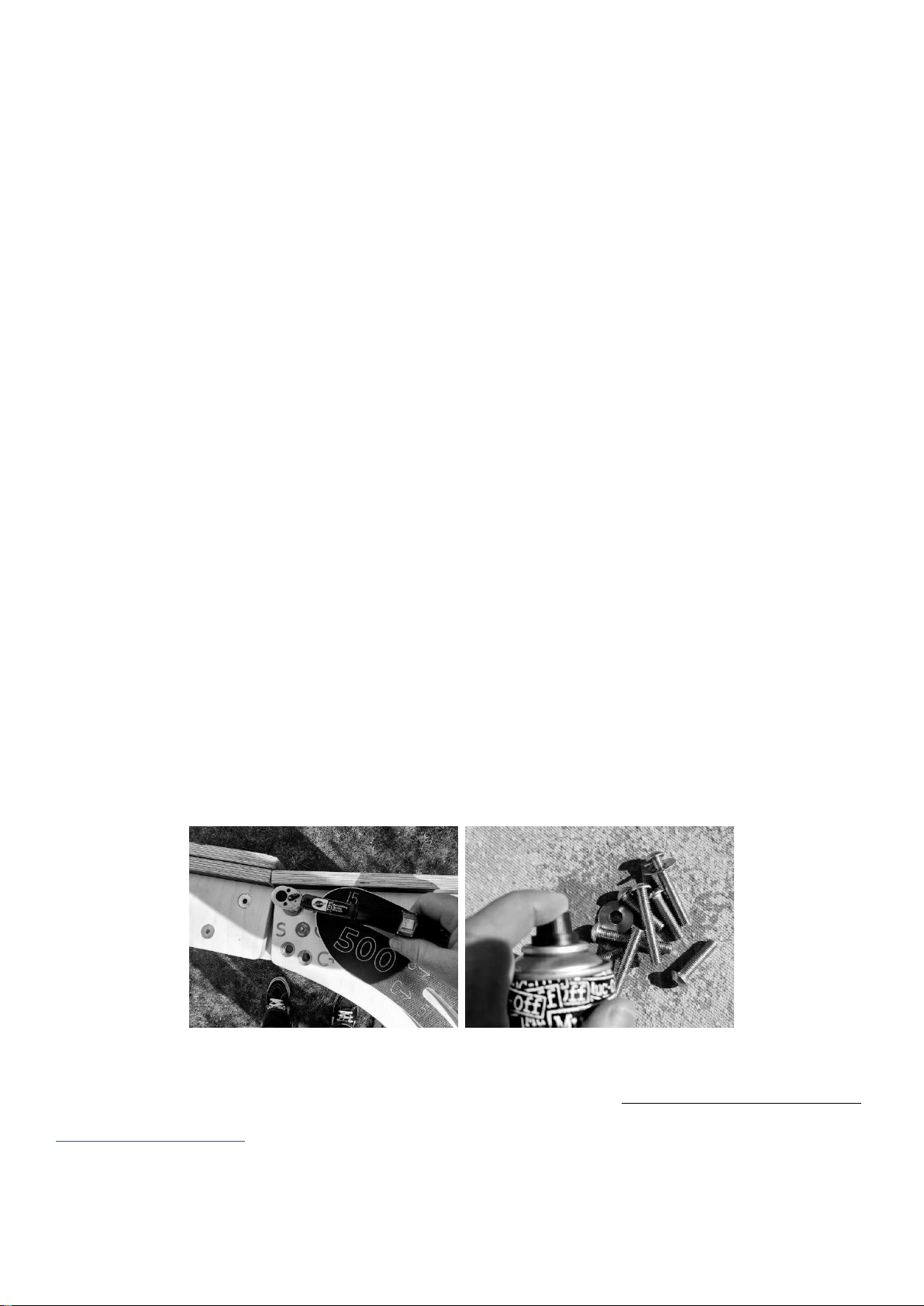
MAINTENANCE:
When you assemble your ramp please use silicone spray to protect and lubricate the bolts. Follow instructions on the bottle /
can for safe use.
Torque Wrench (recommended) –Spray your bolts during assembly process and as often as possible for better function
Moving parts such as Nuts and Bolts should be silicone sprayed frequently. All cut edges and natural plywood faces should be
treated with LOW VOC (Water Based) Decking protector Natural Colour. Repeat annually. Under no circumstances use Varnish!!
Check for damage before and after each use and retire the Ramp if you find any until you seek further advice from
support@sender-ramps.com. Additional notes at the end of this guidebook.
INSTALLATION EQUIPMENT REQUIRED:
1 x 6 mm HEX KEY (Found ON Your Bike Maintenance TOOL!) –SUPER Fast with an Impact Gun with 6 mm Attachment.
A “T” HANDLE 6 mm HEX / ALLEN KEY is useful piece of equipment for tightening bolts
A Torque Wrench will ensure that ALL bolts are set at the max tension of 12 Nm
Your ramp may come unassembled or assembled. Please reads the section appropriate to your purchase.
CORE 200 STRAIGHT AND CURVED RAMP ASSEMBLY
REFRESH KIT: A Refresh KIT will be available in our shop for components in contact with the ground subject to the most wear
and tear. This will keep you jumping for years.
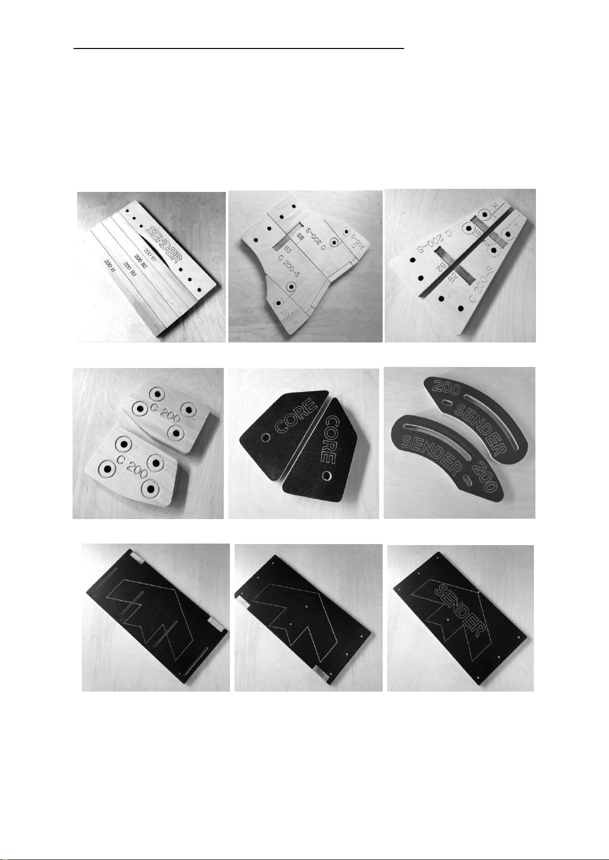
COMPONENTS:
CROSS BATONS / BACK PLATE –REAR SIDE PARTS –FRONT SIDE PARTS
JOINING BLOCKS - FRONT ADJUSTABLE LEGS –REAR ADJUSTABLE LEGS
BOTTOM SURFACE WITH SKATE PLATE SLOTS –MIDDLE SURFACE –TOP SURFACE
VERY IMPORTANT:
STAINLESS STEEL IS SOFT. It is VERY easy to round the heads of screws. Apply CONSTANT PRESSURE when fixing components.
Take your time to complete the ASSEMBLY process. Poor Assembly WILL lead to a weak and poorly functioning product!
ASSEMBLY TOOLS:
1 x Drill Driver
1 x Impact Drill Driver
1 x Pozi 2 Hand Screw Driver
1 x 4 mm Drill Bit
1 x Pozi 2 Driver Bit
1 x TX25 Driver Bit
1 x 6 mm Hex Key
2 x 600 mm Long Quick Wood Clamps
Wear appropriate PPE when assembling your product –Eyewear / Gloves / Footwear. Protect your work space to avoid
damaging your property.
CORE 200 FIXINGS:
6 x 10 x 40 mm Button Head Bolts
6x Large Washers
8x 10 x 35 mm Countersink Bolts
3x 4 x 30 Screws
27 x Stainless Steel TX25 Screws
4x Stainless Steel Hinges
24 x Stainless Steel Hinge Screws
18 x T Nuts
36 x Stainless Steel T Nut Screws
ASSEMBLING YOUR CORE 200 CURVED OR STRAIGHT RAMP
STAGE 1: Time to assemble approximately 1 –1.5 Hrs
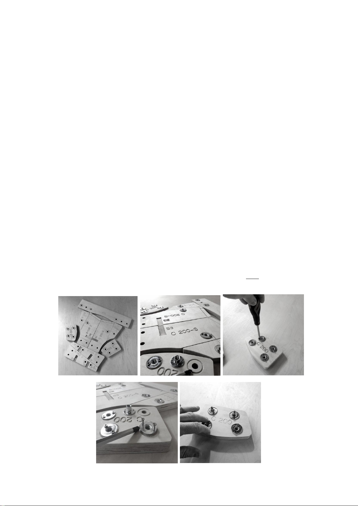
Select all the components with 13 mm holes through the plywood. Lie them on a flat surface so you can see ALL of the CIRCLE /
ROUND Markers around the holes. Place the T nuts into ALL CIRCLED Holes ONLY!
Place the Small Screws into the holes in the T Nuts and fix them to the Plywood. The Screws MUST be placed VERTICALLY! When
complete take the TWO Joining Blocks (Each block has 4 x T Nuts) Use a SCREW DRIVER and undo / unwind the screws 1 turn
until they can be MOVED / ROCKED with two fingers!

STAGE 2:
Take the two FRONT Side Panels R + L and Cross Batons B1 + B2 + H. Place B1 in the VERTICAL Small Pocket at the front of the
structure. Place B2 in the bigger Rear Vertical Pocket. IMPORTANT –H has 3 screw marker points. These must face UP!
WARNING! YOU MUST DRILL EACH HOLE BEFORE FIXING COMPONENTS WITH A SCREW. FAILING TO DO THIS WILL SPLIT THE PLYWOOD. WE
BUILD HUNDREDS OF RAMPS AND NEVER HAVE SPLIT COMPONENTS! DO NOT BE LAZY AND SKIP THIS PROCESS.
Place the 4 mm Drill Bit beside a TX25 Screw and ensure that the drill bit will make a hole the same length as the screw. Use a
Quick Clamp to hold the structure together. You may need to PULL the structure to the edge of the table to drill a straight hole
where the marker is close to the table surface. It is important that you follow the sequence described. Drill through the marker
point in the side panel into the end of B1.
**Secure with a TX25 Screw LEAVING 15 mm PROTRUDING. As shown above**
Next - Drill through the side panel into the end of B2 on both sides and secure FULLY with a TX25 Screw.
Rotate the structure and drill into the other end of B1.
Secure the other side of B1 with a TX25 Screw LEAVING 15 mm PROTRUDING as shown above.
This process makes it easier to locate component H.
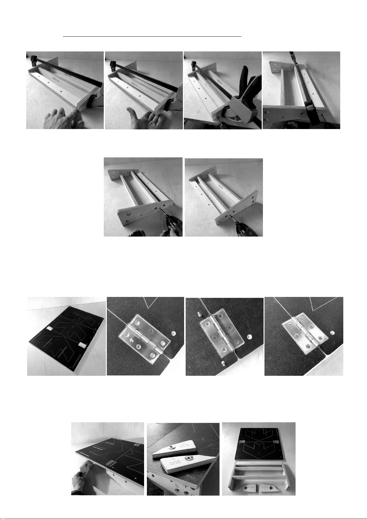
Take Component H and push / place this between the Lower Sides of the ramp where there is Horizontal marker lines. IF H is a
little loose then completely tighten the two protruding screws in B1 (described above). A clamp can also help to hold
component H in place while you check the top and ends are flush.
Drill through the marker points on the lower ramp sides into H and fix with TX25 Screws. You can now drive the protruding
screws completely into the end of B1 at both ends to trap baton H.
STAGE 3:
Take the LOWER and MIDDLE surfaces with the hinge pockets and place them together. Make sure the join is CLOSED. Place a
hinge in each pocket. Centralise / Line the hinge with the join. Place one screw centrally in the hinge on one side of the join.
Place the second screw in the opposing hole. IT IS ESSENTIAL THAT THIS SECOND SCREW IS 1 mm OFF CENTRE TOWARDS THE
LONG EDGE OF THE HINGE! This helps pull the parts together. Place two more screws in one side of the hinge. Next, repeat the
process of OFFSETTING the screws in the opposite side by 1 mm (from centre of hinge hole) to pull the parts together.
STAGE 4:
Take the Hinged Surface and the Structure you have created above and line these components up at the edge of a table. You can
use the joining block(s) to stop the structure from tipping while you complete the next stage. You will need to clamp the
structure to hold the surface accurately to the substructure!
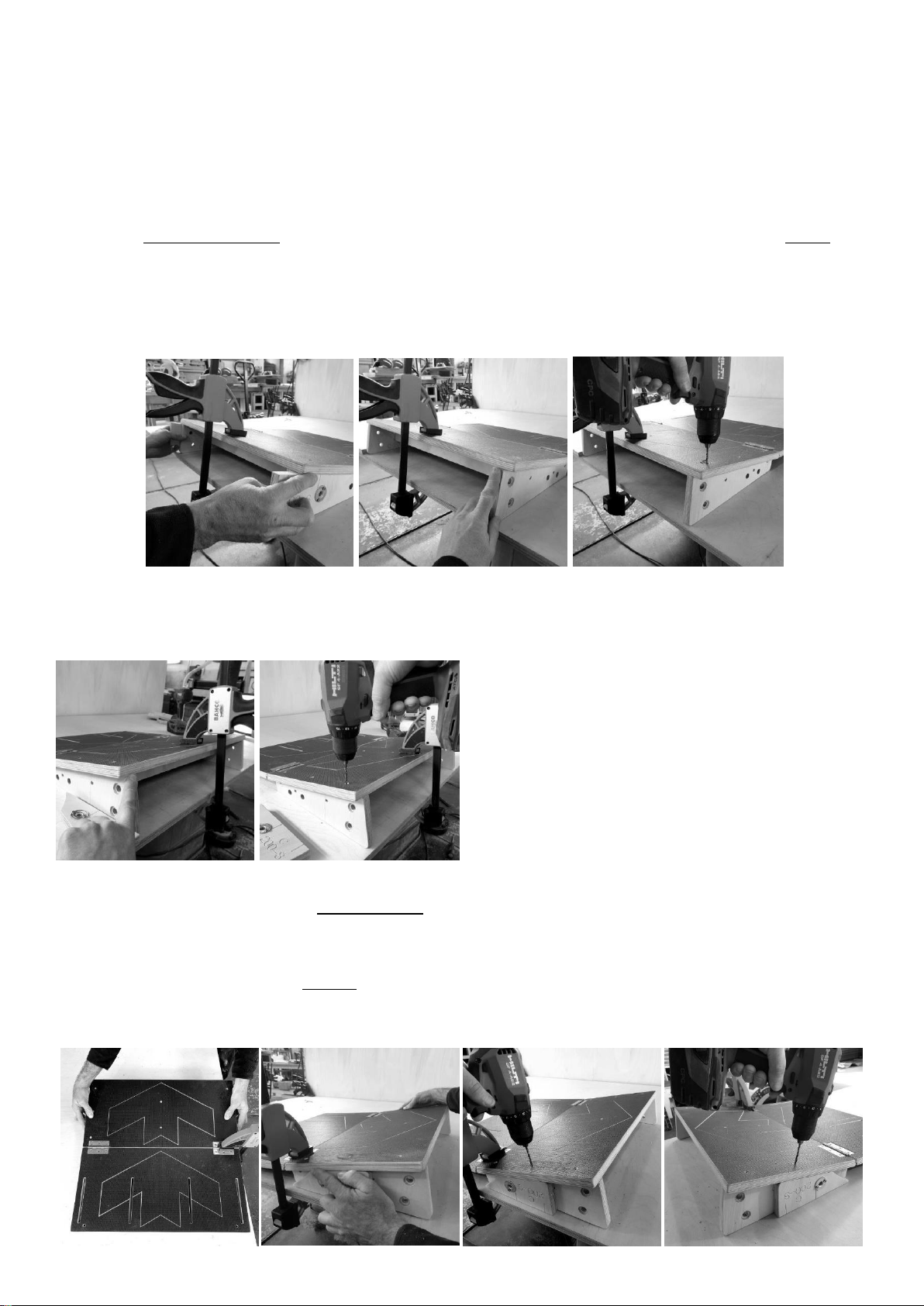
JOINING BLOCKS CAN BE USED TO HELP PREVENT THE STRUCTURE TIPPING WHILE YOU FIX THE COMPONENTS TOGETHER –
COMPONENTS 200 L AND R CAN BE USED AS SPACER BLOCKS (AS DESCRIBED BELOW) TO HELP ALIGN THE SIDES AND
SURFACES
FAILURE TO COMPLETE THIS PROCESS ACCURATELY MAY PREVENT THE RAMP FROM FUNCTIONING PROPERLY AND
MISSALIGN THE SURFACES WHEN BOLTED TOGETHER!
YOU MUST start at the end with the VERTICAL SIDES as these connect with the other part of the ramp. Use components 200 L
and R (IMAGE ABOVE) as 18 mm spacing guides! Place these either side of the surface as shown flush against the sides of the
substructure. BALANCE / EQUALISE by feel and sight so that the surface is sitting EQUALLY above Substructure. It is normal that
the substructure is 0.5 to 1 mm inset from the Surface when using the blocks as a guide. Once you are satisfied that the
BALANCE is correct clamp the surface to the substructure ready for drilling and fixing.
You must also check that the end of the surface and the End of the Vertical Side Panel is TOTALLY flush. Re-adjust if necessary
and Re-clamp. Drill Perpendicular to the surface through the marker point on the surface and secure with a TX25 Screw.
CLAMP THE RAMP SURFACE AND SUBSTRUCTURE TO THE TABLE AND USE THE 200 L / R BLOCKS AS SPACERS
Repeat the same process described above on the other side ensuring the end of the surface and the end of the side panel are
FLUSH.
Turn the structure 90 degrees so that the Edge of the Ramp is lined up with the table edge and repeat the process described
above to SQUARE, DRILL and SECURE the Folding / Hinged end of the Surface to the Substructure.
Components 200 L and R are perfect for lining up the side panels with the surface because the pointed ends fit underneath the
surface at the lowest point. USE THE CLAMP ON TOP OF THE HINGE BAR and UNDER THE TABLE to get a secure and firm grip of
the structure. Drill through the marker half way along the edge of the surface to secure the surface to the side panels.
Repeat on the other side using the middle marker point to secure the surface to the substructure

Remove the clamps and then drill and fix at all remaining marker points. There are 4 more. 2 above the hinges and 2 in the
centre of the arrow.
Turn the entire Structure over. You will see the 3 marker holes in Baton H. Place one of the 4 x 30 Stainless Steel Screws beside
the drill bit and use a piece of tape to mark HOLE DEPTH. IF you drill too deep you will go through the SURFACE of the RAMP!
The Drill holes should be 1 / 2 mm shorter than the Screw. Drill and Secure all 3 points with 4 x 30 Screws. Beware the Stainless
Steel Screws are SOFT! Rounding the heads is possible if you DO NOT apply constant pressure.
STAGE 5:
Select the REAR SIDE PANELS and FOLDING LEGs. Place them together as shown. Take 2 No hinges and place them between the
marker lines on the face of the REAR SIDE PANELS and LEGS. Centralise / Line the hinge with the join. Place one screw centrally
in the hinge on one side of the join. Place the second screw in the opposing hole! IT IS ESSENTIAL THAT THIS SECOND SCREW IS 1
mm OFF CENTRE TOWARDS THE LONG EDGE OF THE HINGE! This helps pull the parts together.
Place two more screws in one side of the hinge. Then OFFSET the screws on the other side by 1 mm (from centre of hinge hole)
to pull the parts together. Repeat on the other Side and Leg.
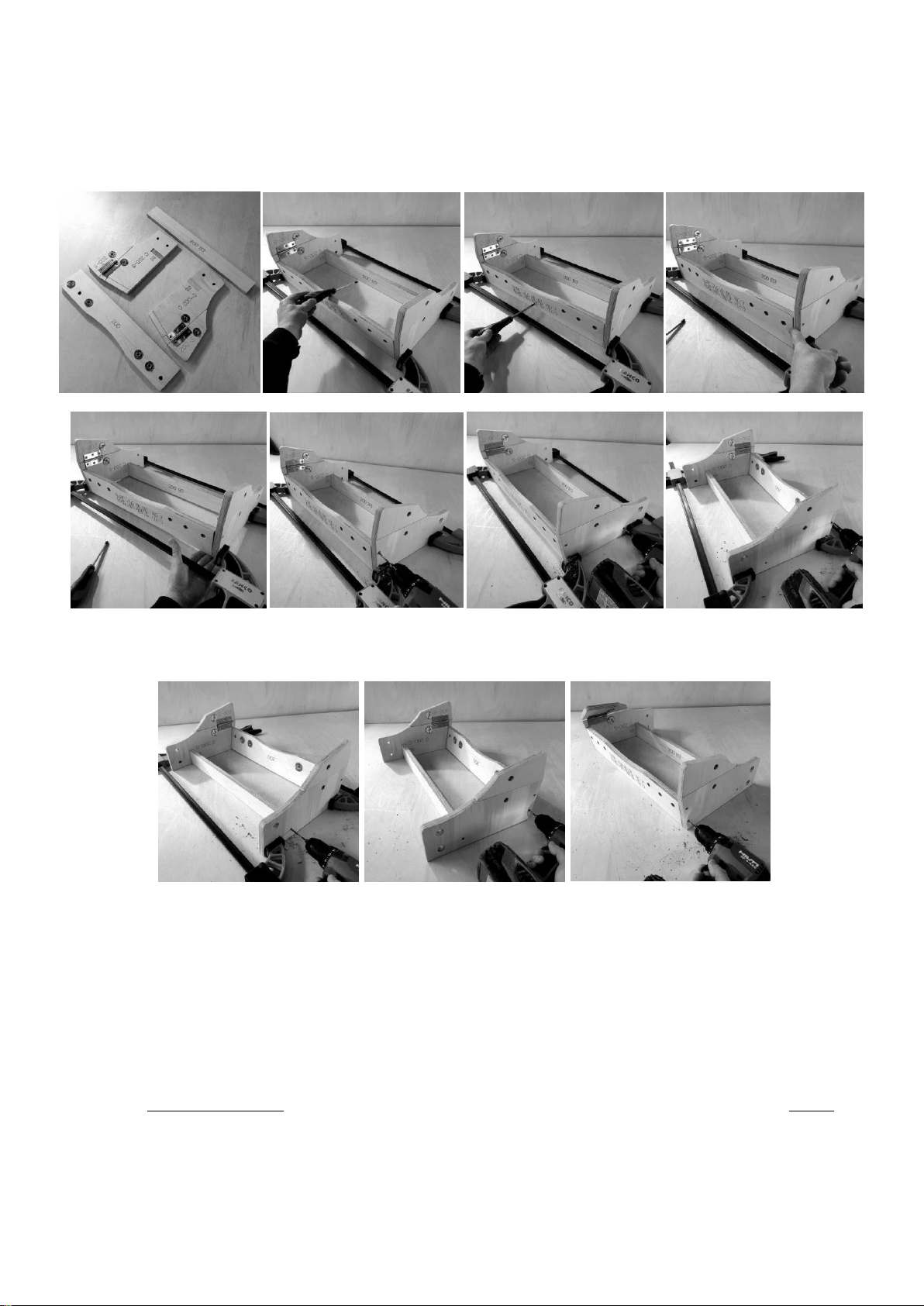
STAGE 6:
Take both Rear Legs and Side Panels now hinged together along with the Back Plate and another B baton. Place B into the
vertical pocket on the side panels. Take the BACK Plate and rotate this so the text is facing out and is upside down. Use two
clamps as shown to hold the structure together. Check that the underside of the Back plate is flush with the vertical and
horizontal Side Panels
Drill through the Side Panels at the marked points into the ends of B and the Back Plate on both sides and secure with TX25
Screws. Remove the clamps, then drill and screw the final 2 holes in the side panels into the BACK PLATE.
STAGE 7:
Take the Top Ramp Surface and the Structure you have created and line this up at the edge of a table. Because of the shape of
the Structure it is best to quick clamp the two parts near the middle. It is important that you hold the surface accurately to the
substructure while you drill and secure with screws.
FAILURE TO COMPLETE THIS PROCESS ACCURATELY MAY PREVENT THE RAMP FROM FUNCTIONING PROPERLY AND
MISSALIGN THE SURFACES WHEN BOLTED TOGETHER!
YOU MUST start at the end with the VERTICAL SIDES (NOT AT THE BACK PLATE) The vertical edges connect with the other part of
the ramp. Use the two JOINING BLOCKS as spacer guides. Place these either side of the surface flush against the sides of the
substructure. BALANCE / EQUALISE by feel and sight so that the surface is sitting EQUALLY above Substructure. It is normal that
the substructure is 0.5 to 1 mm inset from the Surface when using the blocks as a guide.
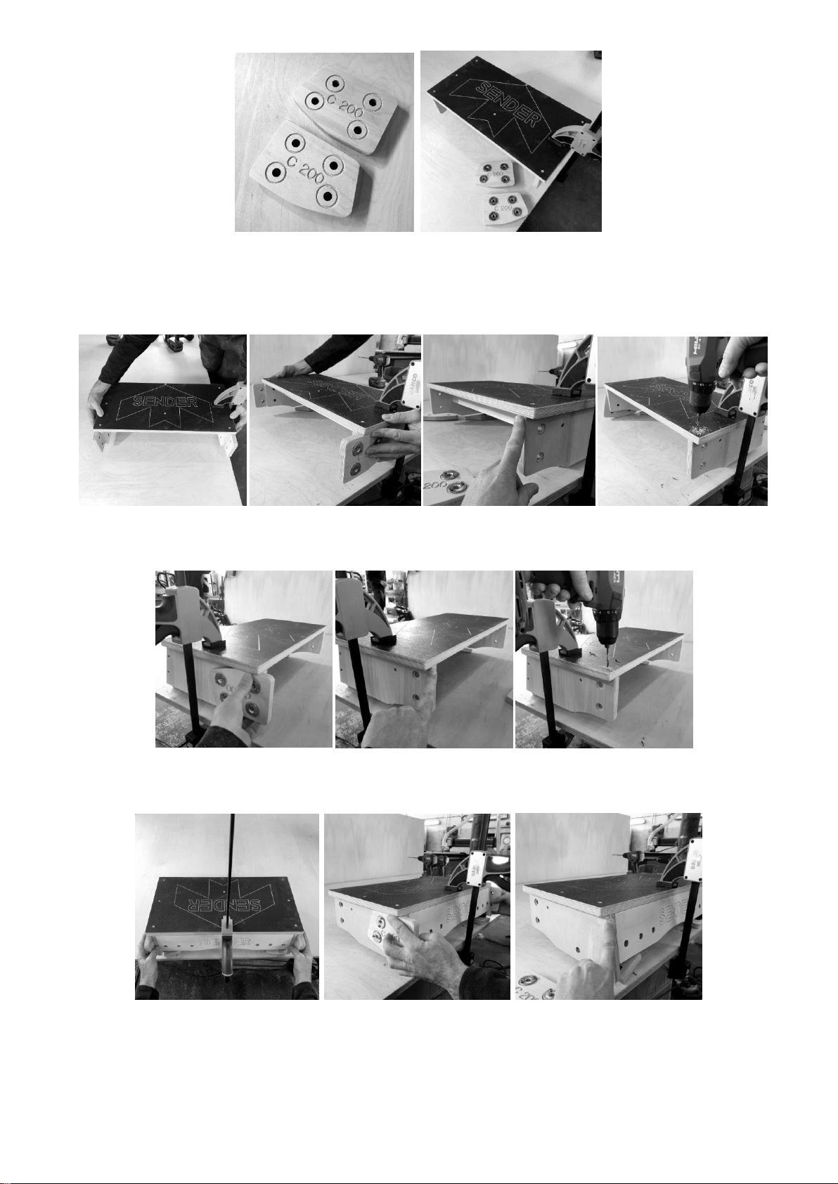
USE THE JOINING BLOCKS AS SPACER BLOCKS
Once you are satisfied that the BALANCE is correct clamp the surface. You must also check that the end of the surface and the
End of the Vertical Side Panel is TOTALLY flush. Re-adjust if necessary and Re-clamp. Drill VERTICALLY through the marker point
on the surface and secure with a TX25 Screws.
You may wish to rotate the structure. Follow the same process of checking with the block and ensuring the end of the surface
and vertical end of the side panel are flush before drilling and securing with a TX25 Screw.
Turn the structure around and repeat the process above to SQUARE, DRILL and SECURE the Back Plate / End of the Surface to
the Substructure as shown below.

The BACK PLATE is also secured in the middle at the edge of the surface. YOU MUST DRILL AND SECURE AT A SLIGHT ANGLE! To
prevent the plywood bulging or the screw appearing on the front or back of the BACK PLATE! There are 3 additional fixing points
on the surface. One on either edge and one in the centre.
STAGE 8:
Installing the joining block. Take both sections of ramp and place them side by side so the VERTICAL JOIN TOUCHES (STRAIGHT
RAMP ONLY) Curved Ramps do not touch. Take the joining block with the corresponding holes as shown below and place this
behind the side panels. There are four PERMANENT fixing bolts points that should only be untightened or removed to relocate /
adjust the block or to place in Super Compact Mode.
Take 4 x M10 x 35 mm Countersink Bolts and place these through the side panel into the T Nuts on the joining plate. Catch the
thread by hand first then wind until FINGER TIGHT ONLY!
Turn the ramp over and fit the second joining plate to the ramp sides with 4 x M10 x 35 Countersink Bolts and wind until FINGER
TIGHT ONLY! PLEASE NOTE THAT THE SIDES OF A CORE 200 CURVED RAMP ARE OPEN ANGLED
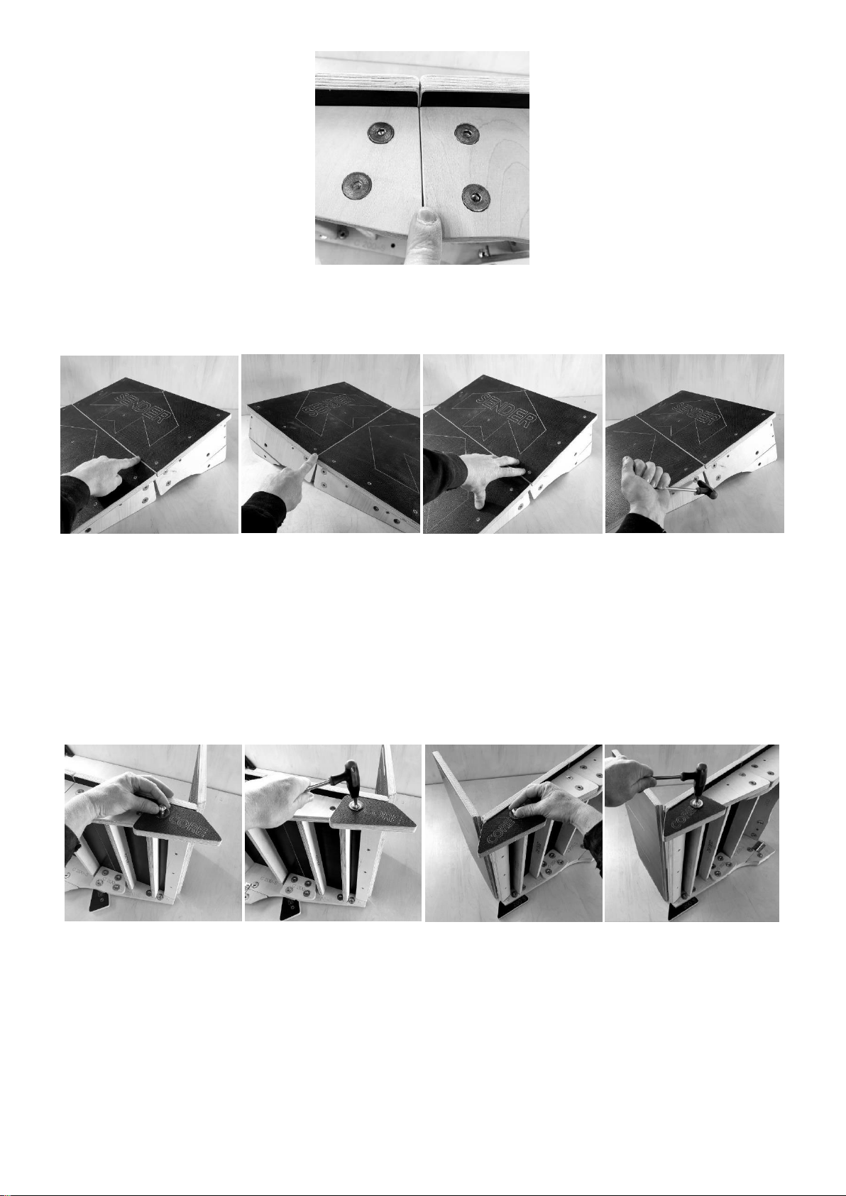
200 CORE STRAIGHT JOIN CLOSED –200 CORE CURVED RAMP OPEN
Turn the ramp over so the surfaces are facing up. Press firmly / manipulate the surfaces at the join so the ramp is STRAIGHT or
CURVED depending which model you have purchased. The Edge of the Surface at the join should be flush / touching!
The Join between the side panels should be closed on the straight ramp and slight open on the curved ramp. Then secure /
tighten all 8 of these bolts. All 8 bolts should be set at 12 Nm for maximum security and checked regularly.
STAGE 9:
Take one FRONT Leg / BLOCKS and place this onto the side of the ramp. Secure the leg to the Side Panel using 1 x M10 x 40
Button Head bolt and one LARGE Washer to 12 Nm. There is ONLY ONE hole in the side panel for this BLOCK / FOOT.
ESSENTIAL: ALWAYS remember to catch the thread of bolts with your fingers first to PREVENT / AVOID CROSS THREADING!
Never use an impact gun / drill to catch the thread.
Turn the Ramp over and attach the second LEG / BLOCK and tighten to 12 Nm.
STAGE 10:
Take one of the Curved Rear Legs and place this onto the side of the ramp. Secure the leg to the Side Panel using 2 x M10 x 40
Button Head bolts and a 2 Large Washers. One bolt goes into the slot and the other into a smaller slot. This smaller slot allows a
small amount of terrain adjustment. The Large slot allows you to swing the legs into storage mode (described later).
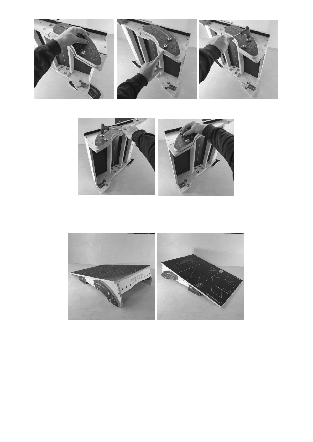
Turn the Ramp over and fix the leg on the otherside.
A REFRESH KIT is available to REPLACE and RENEW components in contact with the ground once they wear out.
Go around ALL the ramp bolts checking that they are tight before starting a JUMP SESSION. You are now ready to TAKE OFF or
LAND using the CORE 200 STRAIGHT or CURVED RAMP.
STORAGE AND TRANSPORT MODES
Your ramp has two storage modes. Compact and Super Compact.
Compact Mode:
Leave the FRONT LEG / BLOCK on the ramp. Loosen the Rear Curved Leg Bolts. REMOVE BOLT 2! NEAREST THE FLOOR / GROUND
and place this back into the T nut for storage once the small leg has fallen out of the way of the Curved Rear Leg. Pivot the leg
around to the point where the Curved Rear sits alongside the Ramp Sides. The Top of the leg should be flush with the back plate.
Tighten the Bolt to hold the leg in place. Turn the Ramp onto the other side and repeat this process. Fold the Ramp Surface
along the HINGE. The Ramp is now in Compact Storage / Transport mode.
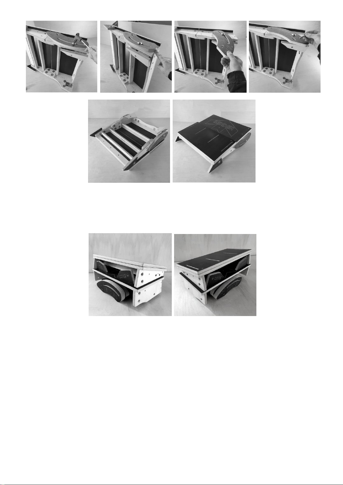
COMPACT MODE CORE 200 RAMP
Super Compact Mode:
Remove the FRONT LEGS / BLOCKS. Remove the Rear Curved Legs. Undo and Remove the joining blocks. Fold the Ramp Surface.
You now have a very compact stack of components. Ensure you store the bolts in a safe place. You may wish to strap the
sections together OR better place in our (optional) transport bag.
SUPER COMPACT CORE 200 RAMP
TERRAIN ADJUSTMENT
Core ramps allow a small amount of adjustment in the rear curved legs for uneven terrain. Simply sit the ramp in the location
you plan to jump and make the necessary adjustments to the back left or right leg. The leg will protrude slightly below the
bottom edge of the ramp. Check all bolts again before jumping.
STORING YOUR RAMP –KEY POINTS TO REMEMBER
Your ramp should be stored in a dry location. Shipping Containers are terrible for humid, warm and cold conditions that are
perfect for growing mould and mildew. Birch Plywood (and other sheet materials) are prone to these growths if it is not treated.
Your ramp CAN BE used outside in the rain and in wet grass but if you would like your ramp to last a lifetime bring it inside after
use. We strongly recommend treating your ramp with a preservative. Please see below.
Never leave your ramp in the transport bag if it has been used in wet grass or in the rain.

SENDER TRANSPORT BAG
Our Transport bags are manufactured in the UK. they are strong but not indestructible. The webbing straps are double welded
but you must avoid picking the ramp up with one strap! Use the Lifting Loop and a strap at the same time to mount the ramp on
your bag.
TREATING YOUR RAMP WITH A PRESERVATIVE
It is not essential to use a preservative but it will greatly increase the longevity of your ramp and prevent unsightly marks. NEVER
use a varnish. Use a water based protector. These are very easy to apply as long as you use a wet, then dry cloth to remove the
excess from all BROWN Surfaces. It leaves a waxy film that peels in the rain! You should coat / treat all cut edges, all birch faces
and any holes / routered text. Preferably twice! And again annually or biannually. A Clear or Natural Colour should not YELLOW
the wood. Ronseal LOW VOC Decking Protector easily and quickly soaks in and dries leaving an effective barrier.
DISPOSING OF YOUR RAMP
You should remove all screws / nuts and bolts and place these in metal recycling. You must put the plywood in the wood
recycling.
BETTER! Get in touch for new parts or one of our refresh kits. This will allow you to keep using the ramp or even sell the ramp to
another user. This is by far the MOST ENVIRONMENTALLY FRIENDLY SOLUTION.
Thanks again –We hope you enjoy the process of building your ramp and then making fast progress to new skill levels and
greater confidence on the trail!
Scott and Team
You can get expert advice at Sender. Do not hesitate to contact us. You can also order replacement parts. This keep your
purchase environmentally friendly and keeps you rolling.
Please subscribe to our YouTube Channel Sender Ramps for notifications when we upload new films. If you need advice or help
please contact us direct support@sender-ramps.com
Table of contents
Other SENDER RAMPS Bicycle Accessories manuals


