SENDER RAMPS PRO CORE SKILLS TRAINER User manual

SENDER PRO CORE SKILLS TRAINER
Thanks for buying our PRO trainer. Front wheel lift is an essential core bike handling skill for ascending, descending, jumping,
bunny hop, drop offs and of course manuals. Used in combination with rolling practice the trainer is a powerful tool that will
help you build confidence and allow you to practice holding the bike at the balance point using weight shift.
What’s NEW!
A massive step forward with no more spacers. We have designed and refined a model which has full mechanical advantages.
You can now micro adjust the width AND clamp the rear wheel with relative ease. Still super strong materials and Stainless Steel
fixings for durability. The sides flex to support the wheel whilst reducing high dynamic loads on all wheel types. The large
platforms are strong to provide lots of lateral support and a solid stable landing surface when you dismount.
Designed for:
Suitable for riders, clubs and coaches - Heavy use including E Bikes.
Fits 20 Inch to 29 Inch Wheels.
**Any Tyre width from 0 to 80 mm Wide –Please NOTE! Below 21 mm you will need to buy shorter bolts from SENDER.
Will fit 16 Inch Wheels with the Special Adapter
Can be used with Resistance Bands (NOT INCLUDED) for strength and conditioning
* It is possible to tighten the 80 / 100 mm bolts so the gap is completely closed. However, the end of the thread will penetrate
beyond the side panel safety blocks and become dangerous! Tyres less than 21 mm require shorter bolts from Sender.
Safe Use:

Always wear a helmet and gloves. Ensure adequate fall space all around especially indoors. Keep spectators clear. Locate the
trainer of a flat even surface. Do not use clipless footwear / pedals. Take your time and follow all the assembly instructions
carefully for max strength. Built confidence before trying harder methods of training. Consult a GP or Coach before undertaking
any strenuous training to avoid injury.
Top Tips:
Trainer –Rolling Practice –Trainer - Rolling Practice. Whole - Part - Whole will see faster gains to becoming a Manual
Master! It is a frustrating and illusive skill that requires determination. Skill gains will improve your general riding ability.
Never stop practicing. The trainer is especially good when you familiarise yourself with a new bike.
Use the trainer for sport specific Strength and Conditioning whenever possible. Hold balances –Use a weight vest!
Do NOT use clipless footwear. It is much safer to use flat pedals so you can dismount
Do not us your rear break. This is a bad habit during practice but an essential emergency lever when rolling. Better to
learn good weight shift to bring the bike back under control.
Remove the “Loop Out” Strap –Get used to dismounting and holding the balance point for 30 seconds first.
Loosen the sides to create more lateral movement –Less support and move like the real thing
Remove your chain –a lot less to push against!
Try different bikes - DH full suss is significantly harder than a BMX or Jump Bike. Hard to Pull Versus fast and twichy!
Always check you pedals are tight to ensure they have not loosened during back pedalling whilst resetting the trainer.
Sender built to last:
Designed and Manufactured in the Highlands of Scotland from 18 mm (13 layer) Birch Plywood and 18 mm (13 layer) Phenolic
Grip (mesh) coated Plywood secured with Stainless Steel Components. Look after your trainer and it will last a life time. We
recommend storing the trainer inside after use and carefully drying the trainer if it is used outside in the damp or rain. Spare
parts are available on request.
Maintenance:
Moving parts such as Nuts and Bolts should be silicone sprayed frequently. All cut edges and natural plywood faces should be
treated with LOW VOC (Water Based) Decking protector Natural Colour. Repeat annually. Under no circumstances use Varnish!!
Check for damage before and after each use and retire the Trainer to seek advice from support@sender-ramps.com
Installation Equipment required:
1 x Battery Power Drill Driver (2 is handy so you do not have to keep changing bits)
1 x Pozi 2 Driver Bit
1 x TX25 Driver Bit
1 x 4 mm Drill Bit
1 x Pozi 2 HAND Screwdriver
1 x 6 mm HEX KEY (Found ON Your Bike Maintenance TOOL!)
Components:
2 x Mesh faced landing platforms
1 x Left side (2 Parts)
1 x Right side (2 Parts)
3 x LB Left Batons
3 x RB Right Batons
1 x No 1 Deck Support
1 x No 2 Deck Support
1 x No 3 Deck Support
1 x Part B (Back bolt end cover - fixed)
1 x Part C (Middle bolt end cover - fixed)
1 x Part F (Front Bolt cover- fixed)
1 x Part T (Top bolt cover –removable)
Fixings:
21 x TX25 Screws
12 x 10 x 35 CSK Bolts SS
25 x T Nuts
6 x 4 x 30 Gold Screws
4 x M10 x 80 Button Head Bolts SS
4 x M10 x 100 Button Head Bolts SS
4 x Hinges SS
4 x M10 x 30 Repair Washers SS
35 x Small 3.5 x 13 SS Screws
24 x 4 x 16 Hinge Screws
1 x Loop Out Straps

Construction Notes:
Please take your time and do a good thorough job of assembly. It may take 2 hours.
Assemble in a location that is flat with plenty of working space to lay components out where they can be easily identified. Place small
parts in a bowl. Protect all work surfaces from damage.
Stainless Steel Screws are SOFT. Maintain constant pressure when fixing these screws to prevent stripping the head of the screw.
Always PRE DRILL HOLES to the correct depth and width 4 mm when indicated to do so in the instructions. If you do not, you will
SPLIT the plywood.
DURING CONSTRUCTION THE TRAINER IS DESCRIBED FROM THE BACK LOOKING FORWARDS
1: Take the RIGHT hand side panels (2 Parts). Take 2 Hinges and 12 x 4 x16 screws. Place the RIGHT parts together as shown and
place the hinges inside the guidelines. Use one of the RB or LB batons to make sure the back edge is aligned / flush.
2: Place and align the hinges with the join which should be closed. Fix the middle screw on one side of the hinge first and then
place the second screw in the opposite middle hole a little (1 mm) OFF CENTRE (towards the long edge of the hinge) This will pull
the join closed when you drive the screw into the hinge. Repeat on the other hinge. Then repeat and fix all other screw points
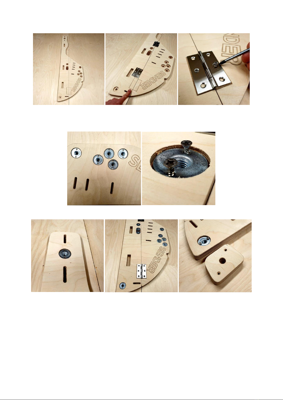
3: Take the LEFT hand side panels (2 Parts). These are slightly different from the RIGHT side. Repeat the process for aligning the
parts and fixing with the hinges and 4 x 16 screws.
4: Keep the LEFT side panel and take 9 x T Nuts and 18 x small screws. Place these into the round pockets. It is better to align the
screw holes VERTICALLY as shown in the next image below. These T Nuts should be fixed with the screws placed Vertically and
NOT at an angle.
Images show the T Nut pockets at the front, middle and rear of the LEFT PANEL.
VERY IMPORTANT.
The next step will allow the T nuts to move. This is vital when trying to cate the thread of the bolt into the nut and greatly
reduces the chance of CROSS THREADING! New T nuts are available from SENDER HQ. Go round every T Nut and unwind the
screws ¼ to ½ a turn so you can feel the T Nut ROCK in the socket. Leave loose but secured!

5: Take Bolt Cover Block B. Place 2 No 4 x 30 Gold Screws into the marker points and align this with the rear edge of the lower
LEFT Panel. Look through the hole and check a bolt can go through the T Nut and come out of the hole! Fix this block in place
ensuring it is flush with the side panel all around. Take Bolt Cover Block C. Place 2 No 4 x 30 Gold Screws into the marker points.
Align this with the folding join on the LEFT side panel and place OVER the 3 T nuts in a row. Ensure bolts can penetrate through
the T nuts and come out the holes! Fix ensuring the block is flush all around.
6: Take Bolt Cover Block F. Place 2 No 4 x 30 Gold Screws into the marker points and align the block between the slots at the
front of the trainer on the LEFT side panel. Ensure the bolt can penetrate the T Nut and come out of the hole! Fix the Block
ensuring it is flush all around.
7: Take Block T and place a T Nut in the pocket. Secure this with 2 x Small Screws. You do NOT need to loosen the screws on this
T Nut!

8: Take Deck Support marked 1 –2 and 3. Take 3 x LB (Left Side Batons). Turn the numbers so you can read them in ascending
order. The LB Batons go in the rails under the LEFT side of Deck Supports 1 / 2 / 3. When you turn Part 1 / 2 / 3 over this is the
end / side with full depth HOLES - NOT the full depth slots!
LB Batons should be flush with the end of parts Deck Supports 1 / 2 / 3 and in the rails. Turn these parts over and drill through
the marker points in 1 / 2 / 3 into LB below. The hole depth should be the same length as the screw 50 mm and using a 4mm
Drill bit. This will prevent splitting the batons.
Repeat the same on all Deck Supports 1 / 2 / 3. Make sure the head of the screw is flush with the surface.
9: Take 6 x T nuts and place these into the bottom face of parts 1 / 2 / 3 beside LB Batons. Fix these with 12 x small screws
Take the LEFT Side Panel and slide this onto Deck Supports 1 / 2 / 3. Deck Support 1 is at the BACK of the trainer. Deck Support 3
is at the FRONT! The number should be readable from the back!

Once the 3 Deck Supports are through the Side panel carefully turn it over so you can see bottom edge of the side panel.
10: Along the bottom edge of the Side Panel are 3 screw marker points. Drill through these points into the end of LB Parts and fix
using 3 x TX25 Screws. These holes should be 50 mm deep by 4 mm Drill Bit. Turn the Trainer back over and take the Left
Landing Platform and 6 x M10 x 35 CSK Bolts.
Place the M10 Bolts through the Platform Surface and locate in the T nuts below. This should be done by hand first to prevent
cross threading. Tighten with a 6 mm Hex Key found on your Bike Maintenance Tool.

11: Take the RIGHT Side Panel and slide this onto the Deck Supports 1 –3. Take 3 x RB Batons and slide these under the RIGHT
Side of the Deck Supports in the groove. Push / locate these RB Batons so they are flush with the ends of the supports.
Drill through the marker points in the Deck Supports into the RB Batons below by 50 mm and using a 4 mm Drill bit. Secure with
3 x TX25 screws in each Baton.
12: Take 6 more M10 x 35 CSK Bolts and 6 T Nuts. Please note that these T Nuts FLOAT (They are not fixed with screws) so that
the RIGHT Landing platform can move in and out to close the gap when you adjust the side panels to your wheel.
Loosely hold the T nut with the positive part in the slot of the Deck Support. Catch the thread of the T Nut from above, through
the top surface of the RIGHT Landing Platform. These can be left loose at this stage.

You can test the movement of this deck by turning the trainer over and pushing and pulling the landing platform along the slots.
If it doesn’t move loosen the Bolts.
13:The next Stage is critical to fitting your tyre / wheel!
In this example we will set the trainer width to a tyre which is 56 mm Wide AND a 29 er! Roughly measure the width of your
tyre.
Look between the Side Panels the Deck Supports below. You will notice numbers! These are guides that show distance in mm
and inches. These will help you when you are trying to achieve an even and parallel gap into which your tyre will fit and then be
clamped.
We will show an example using a real wheel at a later stage but for just now it is VERY IMPORTANT TO NOTE that:
Using the 4 x 100 mm Button Head Bolts will give you SAFE adjustment from a width of 80 mm to 51 mm.
Using the 4 x 80 mm Button Head Bolts will give you SAFE adjustment from 51 to 21 mm
We say SAFE because after 51 mm the END of the BOLT protrudes MORE THAN 5 mm beyond the COVER BLOCKs and becomes a
HAZARD. The 100mm Bolts WILL wind all the way BUT will stick out and tear skin / clothes and damage footwear! SWAP BOLTS
at 51 mm. If your tyre is LESS THAN 21 mm we strongly recommend you by 4 x shorter bolts available from Sender.
We will start by using the DEFAULT 100 mm Bolts as these will allow adjustment past 56 mm. IF you were using the 80 mm bolts
and going from 51 mm or less the process is the same except the starting gap is 51 mm and NOT 80 mm. Set the Right Side
panel at the 80 mm wide position. Take a 100 mm Button Head Bolt and place this through the hole at the REAR of the Trainer
as shown. Place a Washer over the bolt end –then wind on 2 No Nuts and then add a second Washer. Push the bolt through
until it connects with the LEFT Side panel and wind into the T nut a few threads.
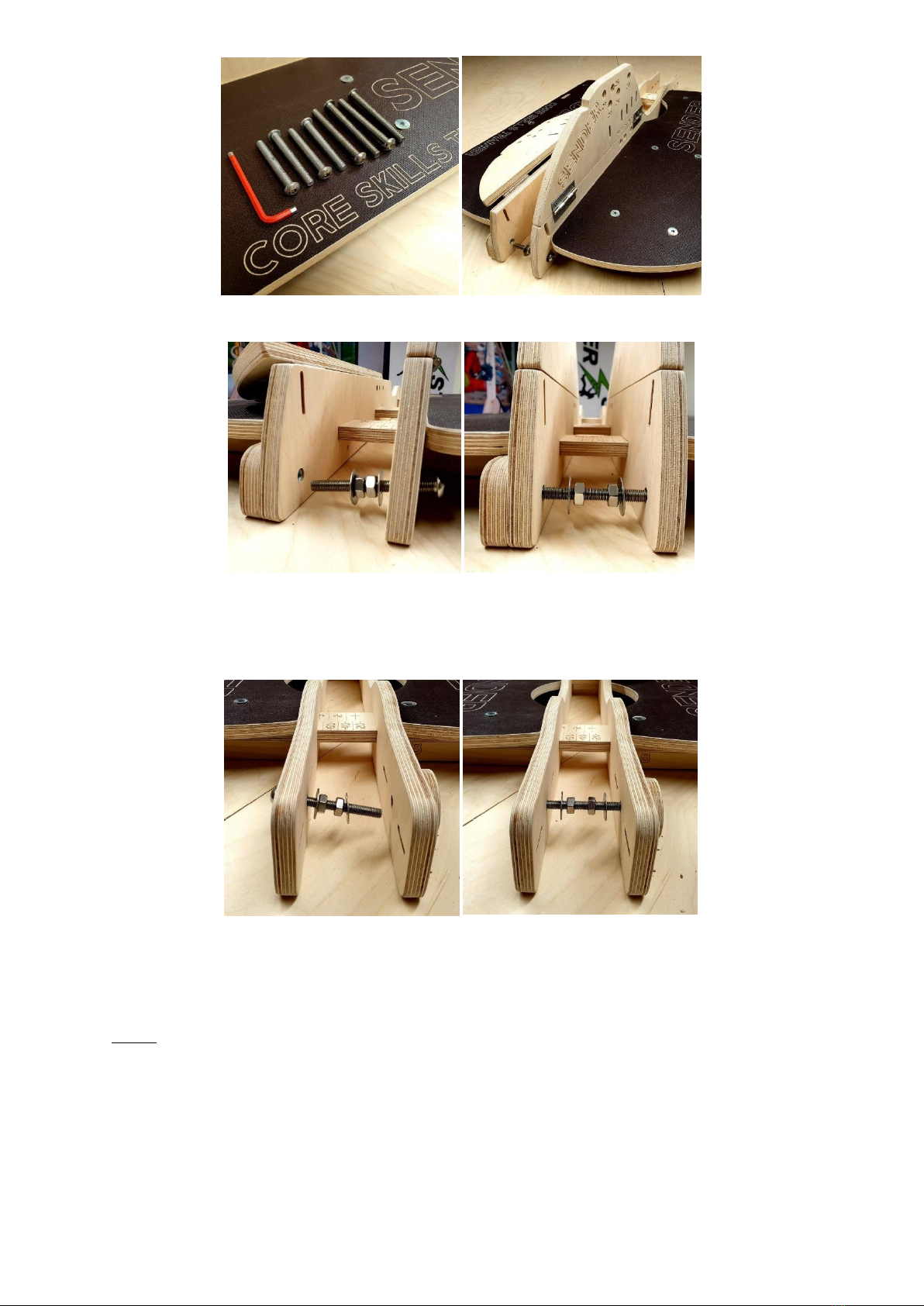
Image ABOVE shows 4 x 80 mm Button Head Bolts and 4 x 100 mm Button Head Bolts supplied with your trainer.
Move to the FRONT of the Trainer. Set the Right Side panel at the 80 mm wide position using the marks on the Deck Supports
(The RIGHT Side Panel is now on the LEFT!). Take a 100 mm Button Head Bolt and place this through the hole at the FRONT of
the Trainer as shown. Place a Washer over the bolt end –then wind on 2 No Nuts and then add a second Washer. Push the bolt
through until it connects with the LEFT (right) Side panel and wind into the T nut a few threads.
14: Choose the wheel size you will be using. These bolt locations will never be exact because there are so many different types
of tyre tread and tyre wear! But they are close enough for the purposes of the trainer. Reminder: We are 29er for this example!
20
24 / 26
27 / 29
16 Inch Adapter Instructions with the NEW ADAPTER.
Place 1 No 100 mm Button Head Bolt through the LOWER holes in the RIGHT Side panel at 27 / 29. Then place 1 No 100 mm
Button Head Bolt through the UPPER 27 / 29 Hole. IF you have problems locating the bolt on the thread NEVER force the bolt or
you WILL cross thread. IF the bolt will not catch the thread of the T Nut remove the bolt from the RIGHT side and try and place it
directly into the T nut to check it works. Sometimes it can take a little time and patience. Once it is working replace it through
the RIGHT side and catch the thread. A little silicone spray can help if the trainer is well used and the bolt has grit on the thread!
Maintenance . Make sure the T Nut is LOOSE. This is an assembly stage. A loose T Nut is easier to locate!
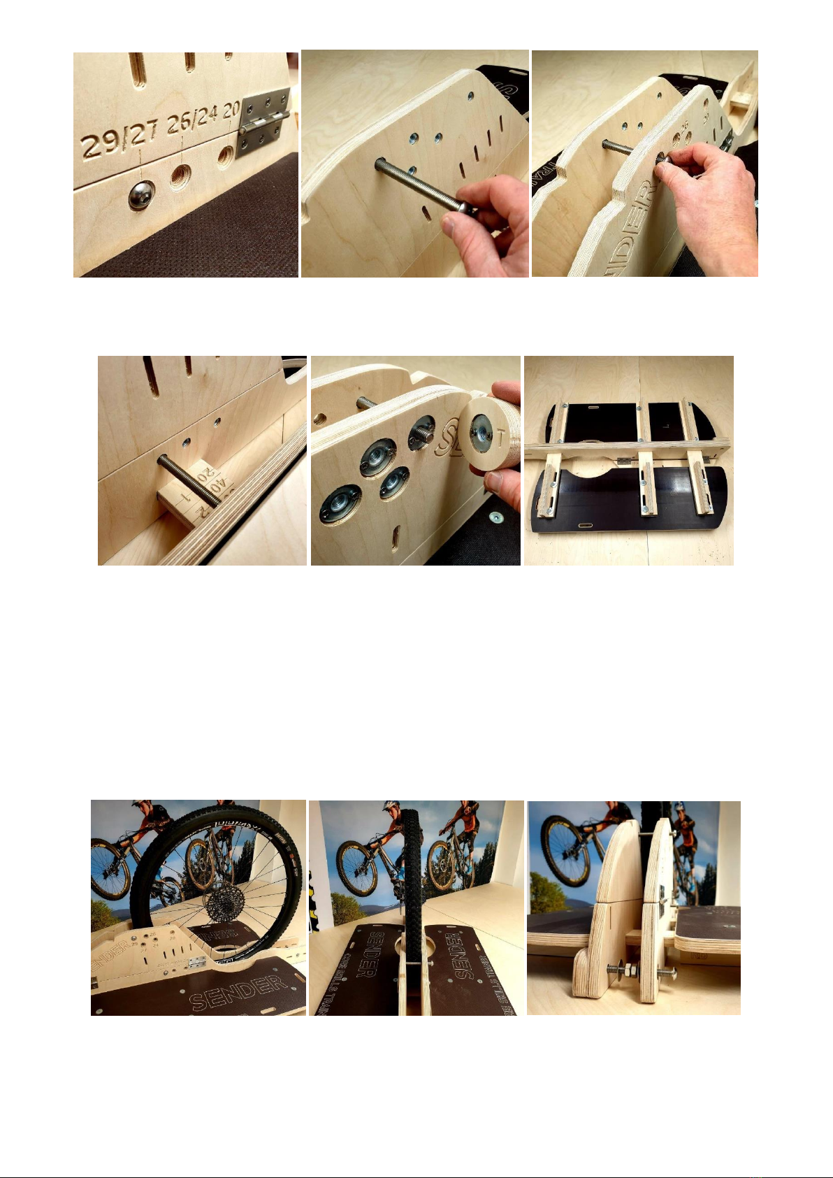
The final component is the removable BOLT COVER “T”with the T Nut in the centre. This is used on the TOP bolt when the BOLT
THREAD protrudes more than 5 mm through the LEFT side panel. It MUST BE USED or you risk damaging you clothes / shoes /
lower body! Before moving onto the next stage make sure the Landing platform can slide.
For ease of description the process of fitting a wheel is shown without the rest of the bike attached. Reminder: For Illustration
we are using a 29 er wheel which is 56 mm wide.
INSTALLING THE BIKE / WHEEL AND ADJUSTING THE TRAINER TO FIT
14: The bolts are already set in 29er position from our example above. Ensure the tyre has at least 25 psi. In some cases, you
may need more.
Place the wheel in the trainer. Slide the RIGHT Side panel across to rest against and trap the wheel. Wind the REAR bolt into the
T nut until you get to the desired width. You can use the markers on the Deck Supports to help. You can always make fine
adjustments later. When you are happy wind the nuts in opposite directions to trap the washers against the LEFT and RIGHT side
panels. This prevents the side panels from moving.
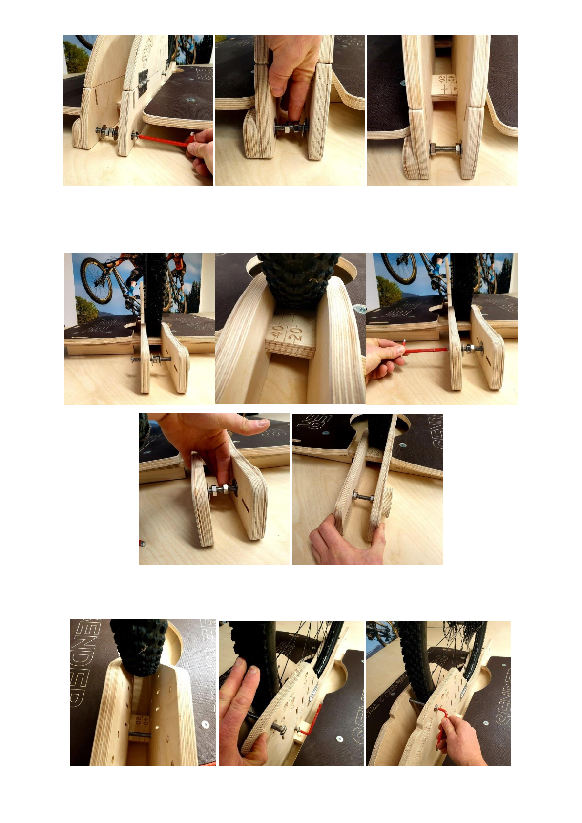
15: Turn the trainer around so you are now at the front. Tighten the bolt at the FRONT so you move the RIGHT side panel to the
desired width. Check that the sides are parallel. Wind the NUTS in opposite directions to trap the washers against the sides and
stop any movement. IF you do not complete this process and the front panels can bend inwards they may break! Check by
Squeezing!
16: Tighten the MIDDLE Lower Bolt keeping the sides parallel. You can move the wheel forward a little to check the width is
correct using the markers however the tyre should not move without a firm pull. A FRICTION FIT! Push the tyre back into
position and wind the TOP bolt which will fully trap the tyre / wheel and prevent the wheel from moving.

Before progressing you should try and move the wheel and ensure it cannot be removed by hand. You may need to tighten each
bolt a little more. Place / Spin Bolt Cover T onto the THREAD sticking out of the trainer. VERY IMPORTANT SAFETY POINT.
DANGER: CHECK ALL BOLTS ON THE LEFT SIDE. IF THEY PROTRUDE MORE THAN 5 mm YOU MUST CHANGE BOLT SIZE to 80 mm
or less.
17: Finally slide the deck against the RIGHT side panel and tighten all the M10 x 35 CSK Bolts. A loose moving
platform is very dangerous.
ADDITIONAL SECURITY STRAP
An EXTRA strap can be used to hold the wheel when you use the trainer. This can be useful at events or at clubs or during
coaching when many attempts during the day can lead to wheel creep. Below you will find a guide to using this feature. Strap
not included
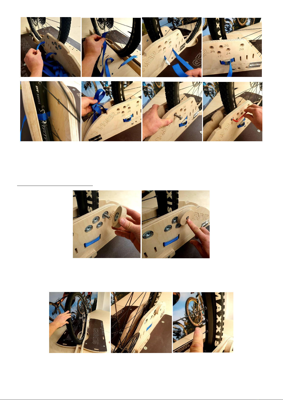
Undo the TOP Bolt and fold the sides down. Thread the strap through the rear slot on the RIGHT side panel. Pass it through the
opposite slot in the LEFT side panel and pull the slack through keeping the strap twist free. Choose the most suitable slot to
thread the strap that will sit over the rim of the tyre and pull it back tight against the bolts. Thread it through the opposite slot
on the RIGHT side panel. Pull the strap through and thread through the CAM BUCKLE. The EXCESS strap can go back through the
first slot and sit in the space behind the tyre / wheel.
Replace the Bolt Cover before practice!
Beware of Spokes touching the side panels:
This can happen on bigger wheels and can be resolved by increasing tyre pressure. It would be normal to step off before
extreme / excessive lateral movement happens. During advanced practice with less support it is assumed enough control has
been achieved that the bike will never lean this far for spoke contact to be a problem.
FITTING AND USING THE LOOP OUT STRAP:
Always check the strap for wear before each use and replace it when the tape is showing fraying / wear. Pass the strap through
both slots at the front of the trainer. Loop the strap over the bottom tube above the bottom bracket and pass the end through
the CAM BUCKLE. Tuck the strap behind the chain ring (you may need to do this several times during practice)
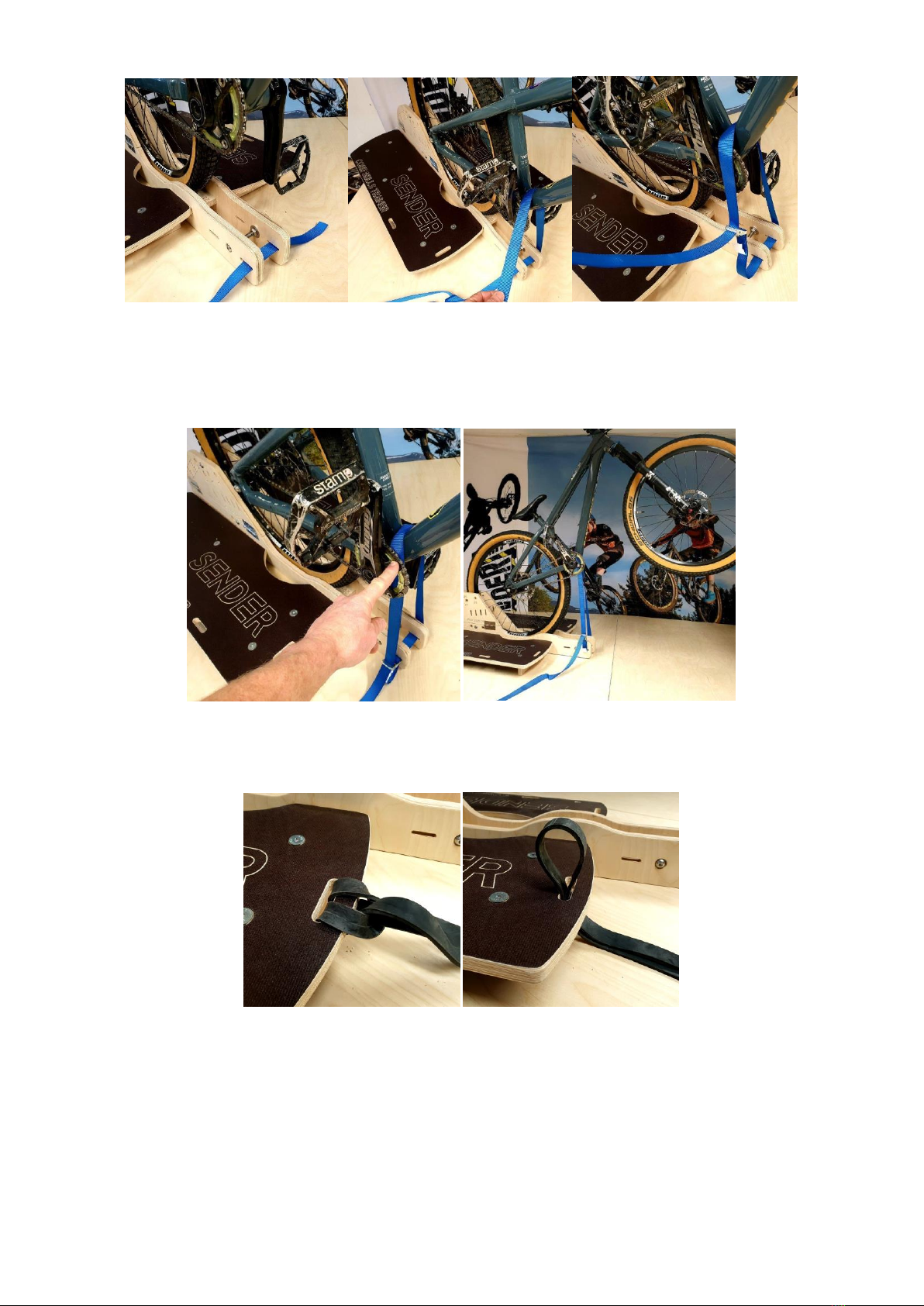
ADJUSTING THE STRAP LENGTH:
We recommend that you adjust the strap so the bike is at an angle of about 30 –35 degrees to start with. You can increase the
length of the loop as you gain confidence that the strap will hold you. The balance point is quite low for a manual. But during
early practice sessions you may find yourself pulling a long way back and looping out! Step off in control.
RESISTANCE BAND ANCHOR POINTS:
The Trainer has been designed so you can anchor resistance bands to the platforms to train core strength and conditioning. You
can also attach a pair to the handlebars of the bike which adds a challenging twist to bikes specific training sessions. Bands not
included
TRANSPORT AND STORAGE:
The sides fold flat to make the trainer easier to store and transport. Simple remove the top bolt and attach the bolt cover so it
does not get lost. You can hang the trainer from the back. The rear edge of the sides has 2 slots through which you can thread a
strap.
BIKE REPAIR STAND:
The Sender Repair Stand will bolt onto the new trainer only at the 80 mm (wide setting). It will function exactly the same in this
position.
BIKE STAND:

The Bike Stand will fit onto the New trainer but is not included. You need to adjust the trainer to the 80 mm (wide setting) to
attach this component in the same place.
You can get expert advice at Sender. Do not hesitate to contact us. You can also order replacement parts. This keep
your purchase environmentally friendly and keeps you rolling.
Please subscribe to our YouTube Channel Sender Ramps for notifications when we upload new films. If you need
advice or help please contact us direct support@sender-ramps.com
Table of contents
Other SENDER RAMPS Bicycle Accessories manuals


 product manual")


