SENDER RAMPS STREET RAMP L1 EXTENSION User manual

STREET RAMP L1 and L2 EXTENSION
DESIGNED FOR BIKES - SKATEBOARDS –SCOOTERS
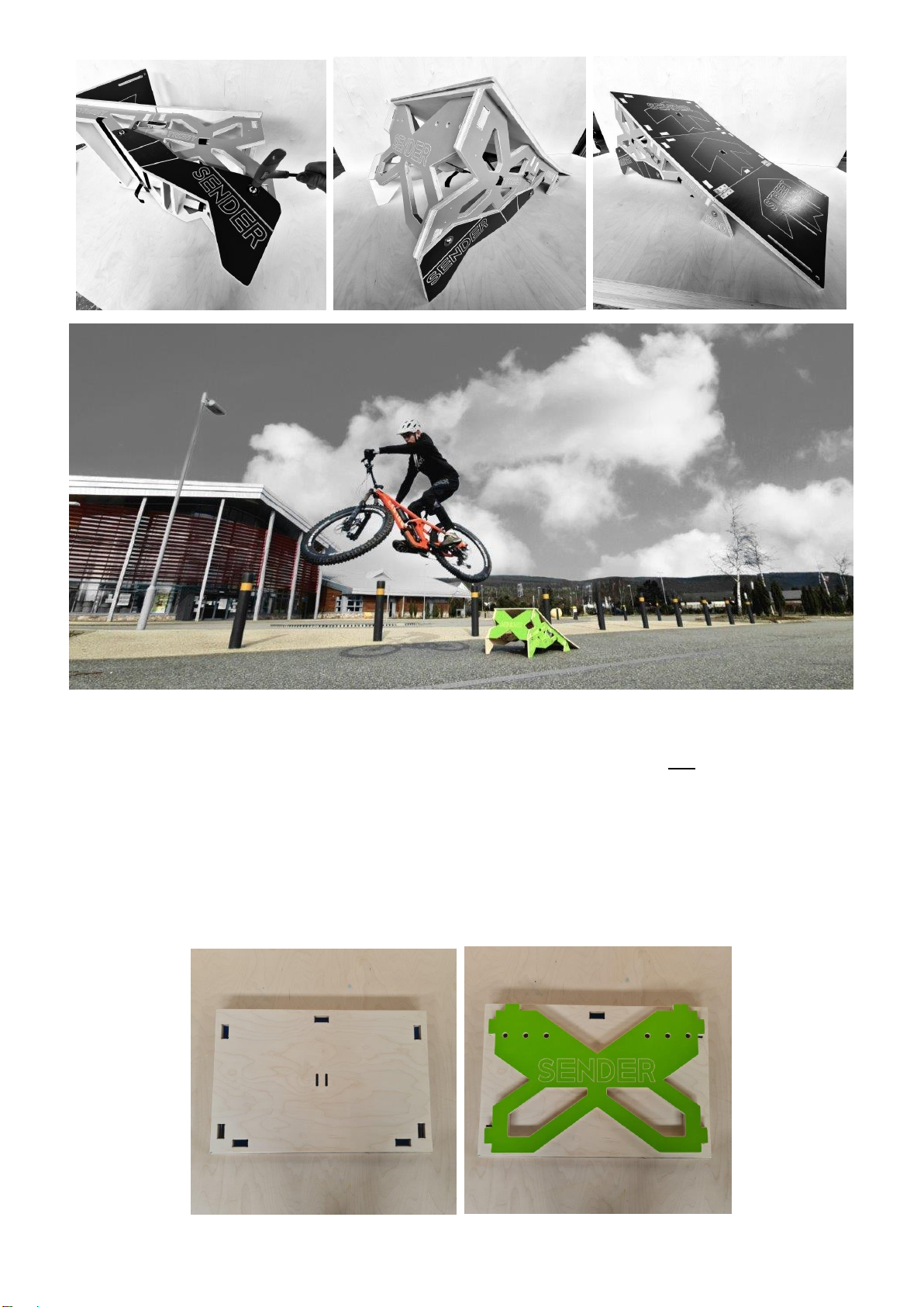
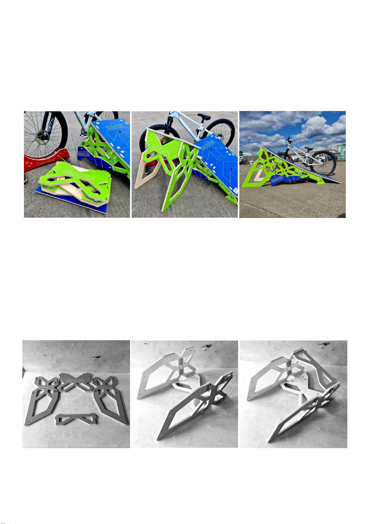
The New Sender Street Ramp L1 has 3 Curved take off heights of 200 mm 350 mm and 500 mm. The L2 Extension
(Additional Product) bolts to the L1 to create a ramp 750 mm high! The L3 (available soon) will be 1000 mm! Sender
Street Ramp L1 is super compact when folded at just 600 mm x 410 mm x 190 mm. The ramp is made from super
strong 18 mm Birch Plywood and only weighs 18 kgs. Once attached the L2 makes the Ramp 29 kgs. The L1 ramp can
be turned into a rucksack to carry to the park with simple straps. Parents and Guardians of young children should
assess the child’s ability to carry this ramp safely to its point of use. A Strong Vinyl bag is available for the L1 and L2 if
you prefer a better carrying solution. The L2 should not be attached to the L1 and used in rucksack mode with the
straps alone.
The ramp can be assembled for use in less than 1 minute. There are no screws. The structure pushes together and
each section is held with a super strong strap. The 200 and 350 Section are held with heavy duty clips. Placing the
ramp into 500 mm High mode requires legs to be attached with 6 x M10 Bolts. These are inside the small cotton bag
with a 6 mm hex key. You will also find a Hex key on most Portable Bike Tools if you lose the supplied Hex key.
The ramp is coloured with an exterior grade preservative. It is important to coat all other edges and faces with a
clear wood preservative if you would like the ramp to last and function properly. Maintaining your product will
greatly increase its life span. We recommend treating your ramp annually and spraying bolts and T nuts regularly.
Always bring your ramp inside to dry after use. Wood can swell and jam. Some components have small tolerances to
ensure a strong stable structure.
Never drag your ramp around. Lift and place the ramp where you will jump to avoid damage to ground contact
points. You can use the ramp on all surfaces as long as it is flat and even and the sides / feet do not sink.
ALWAYS CHECK YOUR RAMP IS PROPERLY ASSEMBLED BEFORE EACH TAKE OFF
Jumping can go wrong very quickly and lead to severe or even life changing injuries and damage to you bike,
skateboard, scooter and property. We recommend grass take offs and landing when using a bike. Always wear a
helmet, knee pads and gloves as a minimum. Ensure clear take-off and landing space all around and if used on the
street locate and jump in a safe place with no chance of striking or being struck by a car, van etc.
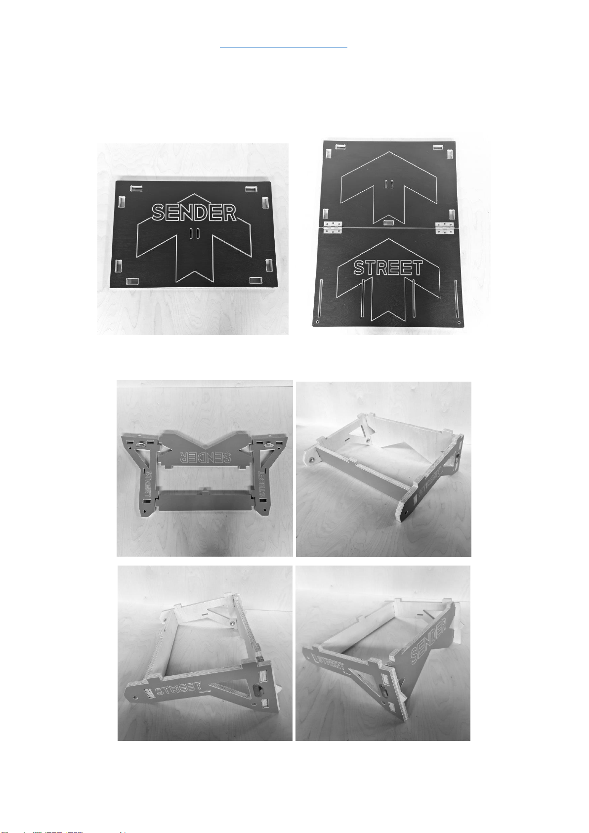
CREATING a 200 mm HIGH RAMP!
STAGE 1:
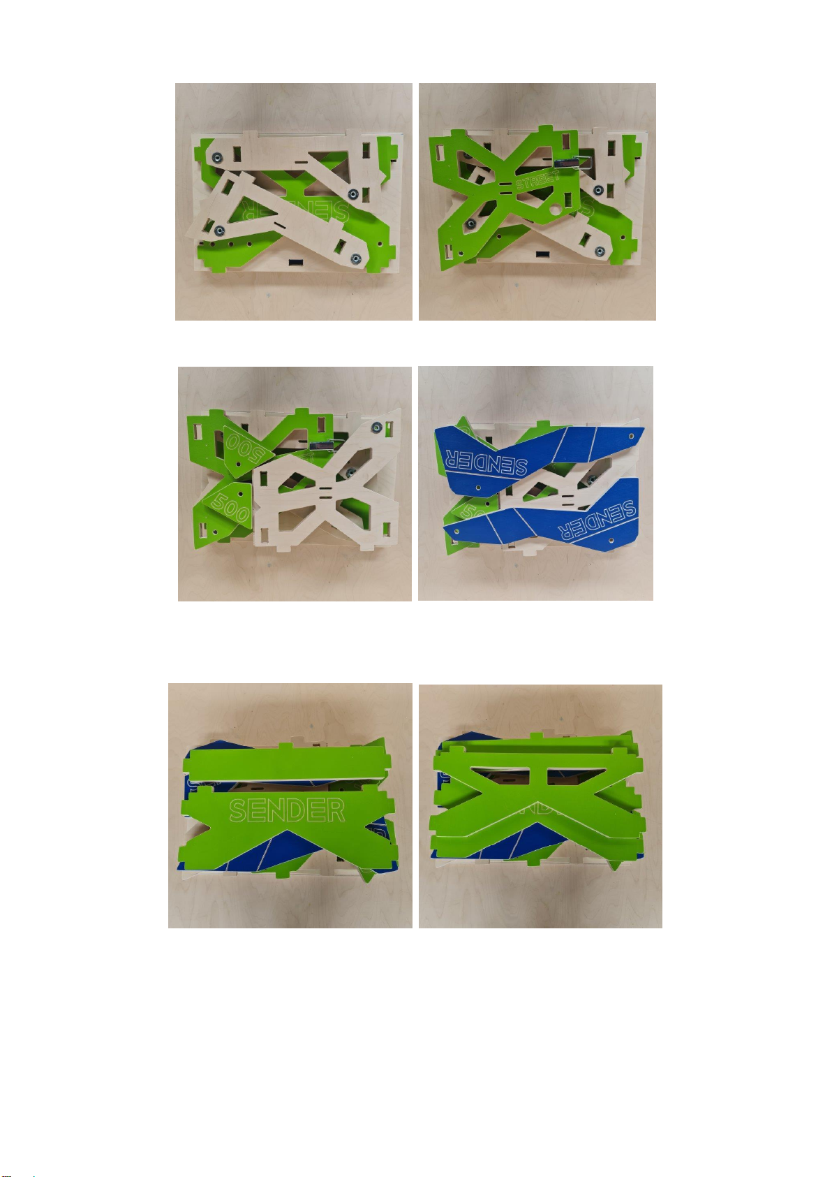
Your Ramp Surface comes in two parts. The Top section is a single deck. The Lower section has 2 decks and is hinged.
Start with the two short side components. The rectangular front brace and the X shaped smaller SENDER back brace.
These components should be laid coloured side up! Push the parts together as shown below
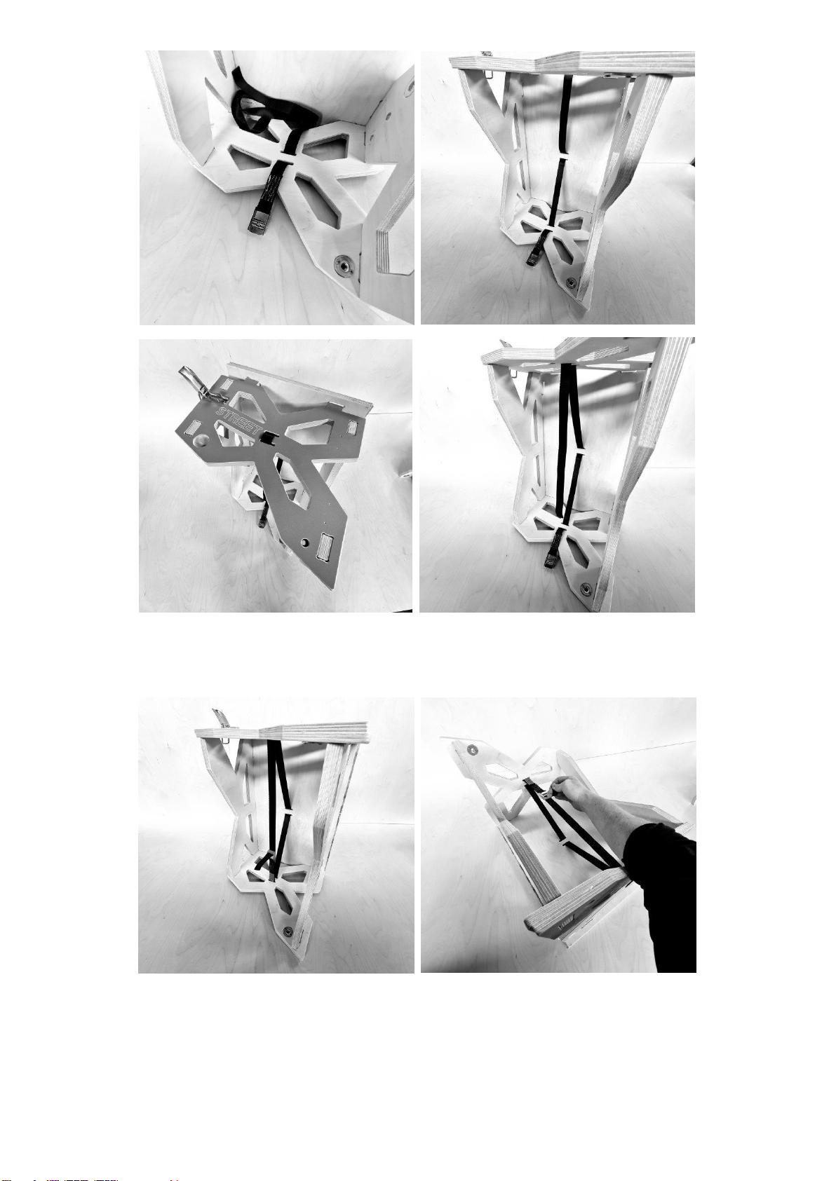
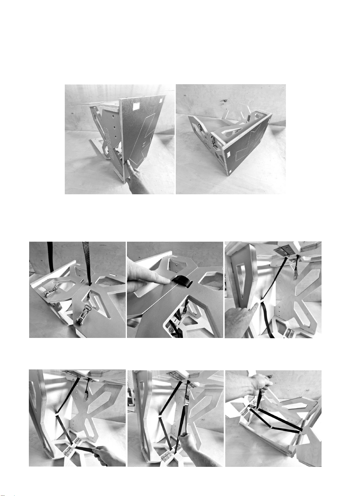
Place the Lower Hinged Ramp Surface onto the frame. Carefully lift and place the ramp on its side holding the
components together. It is possible to complete this stage in other ways. However, this method is the best to see
how the strap works. Thread the strap under one side and through the slot. It is important to ensure the straps are
always threaded WITHOUT TWISTS and the Cam Buckle is the correct way up! You may need to go back to the start
and rethread on your first attempt.
Feed the Strap through the ramp surface and return to the back face. Thread the strap through the slot in the
opposite side component and place the strap over the edge. Remove any twists. Thread the strap through the Cam
Buckle.
Give the strap end a firm pull to connect all of the components securely. Turn the ramp over onto its surface. Give
the strap another firm pull. This will ensure the ramp is secure and all components held together.
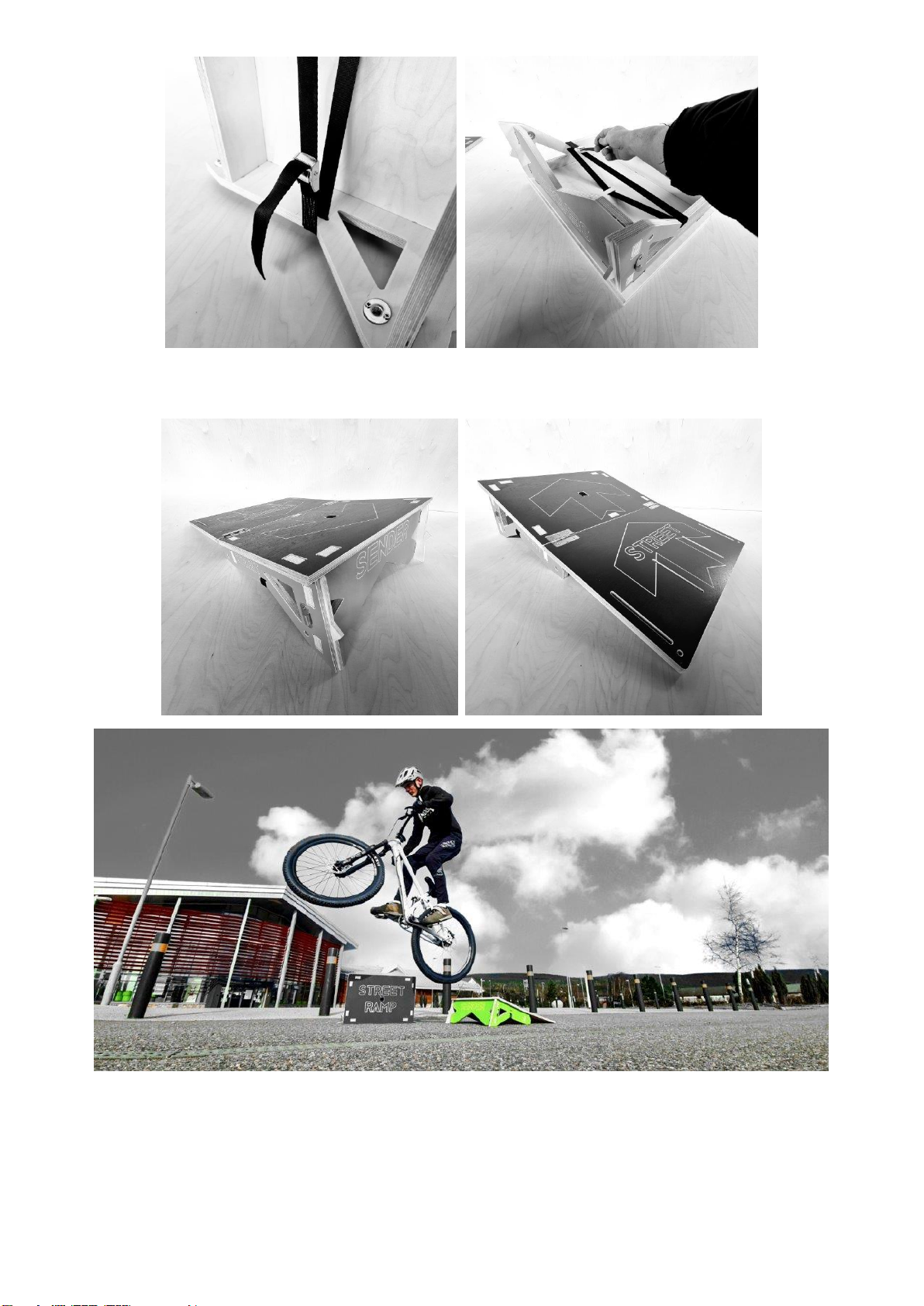
Turn the ramp back over and unfold the surface. You have now created a 200mm High Jump Ramp. If you have
chosen a skate plate to go with your ramp, please visit that section of the guide to see how it is fitted and adjusted.
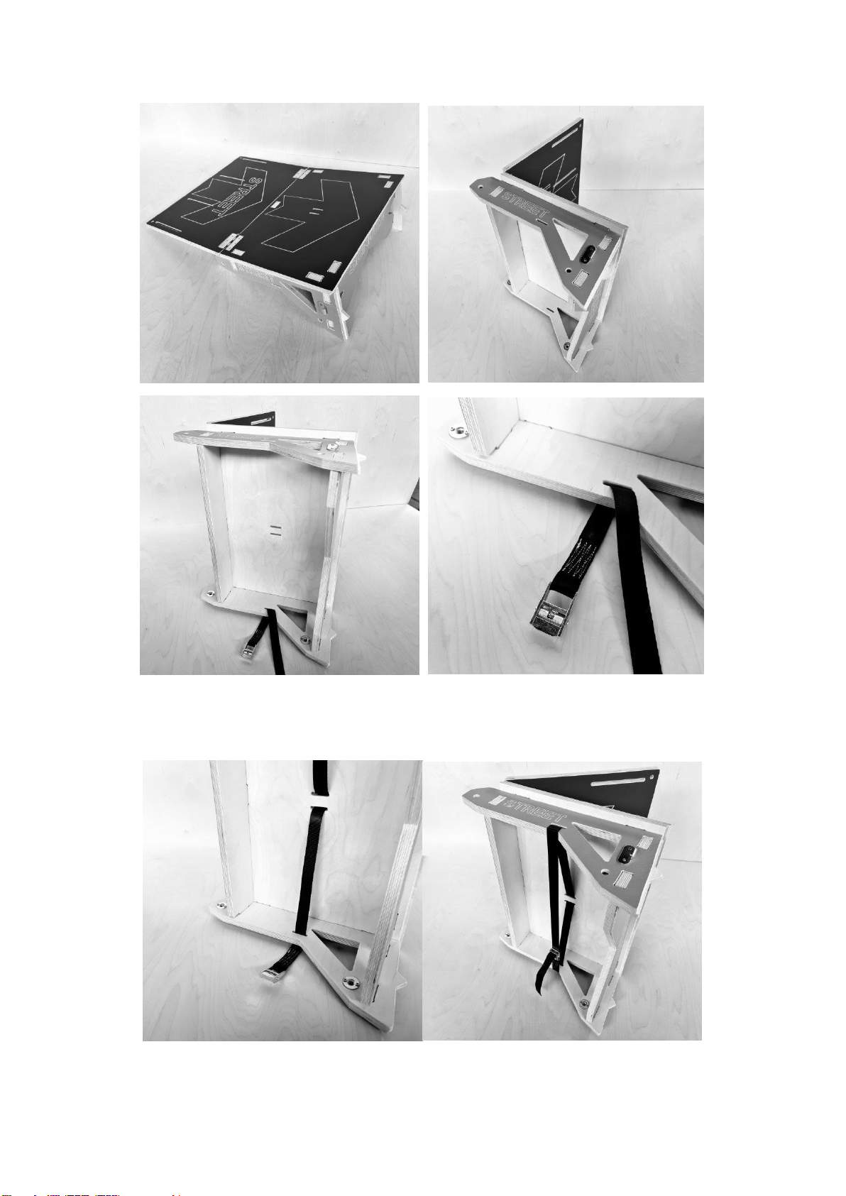
CREATING A 350 mm HIGH JUMP RAMP
STAGE 2:
Lie the Large SENDER X back brace down coloured side up. Do the same with the X shaped side
components and X shaped front brace. Push the parts together. The clips should be at the lower end of the
structure on the outside of the structure.
Place the Single Deck onto the Structure and carefully hold and turn these components onto one side as shown
below. The next stage can be completed in other ways but this is the best way to demonstrate the strapping system.
Starting on the inside face, thread the strap through both slots in the side component. Thread the strap through the
ramp surface. Thread the strap through the slots in the other side component.
Remove any twists and ensure the Cam Buckle is facing the correct way to get a clean, straight pull on the strap.
Thread the strap through the cam buckle and pull firmly to hold the components together. Turn the ramp onto its
surface and give another firm pull to secure the parts.
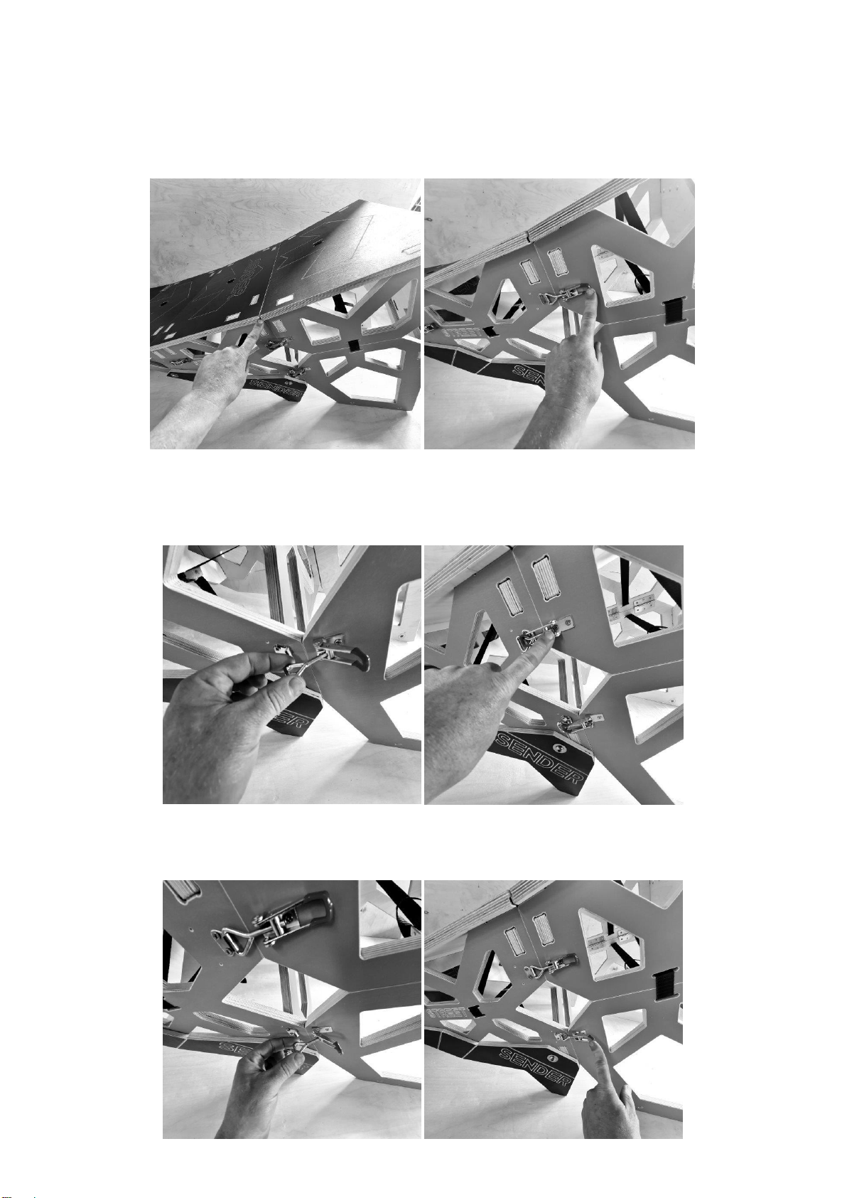
JOINING THE 200 to 350 EXTENSION
Complete this next stage on a flat surface to avoid damage. Place the 350 TOP section behind the LOWER 200
Section. Align the sides and slide them together. Make sure that the components are flush all around.
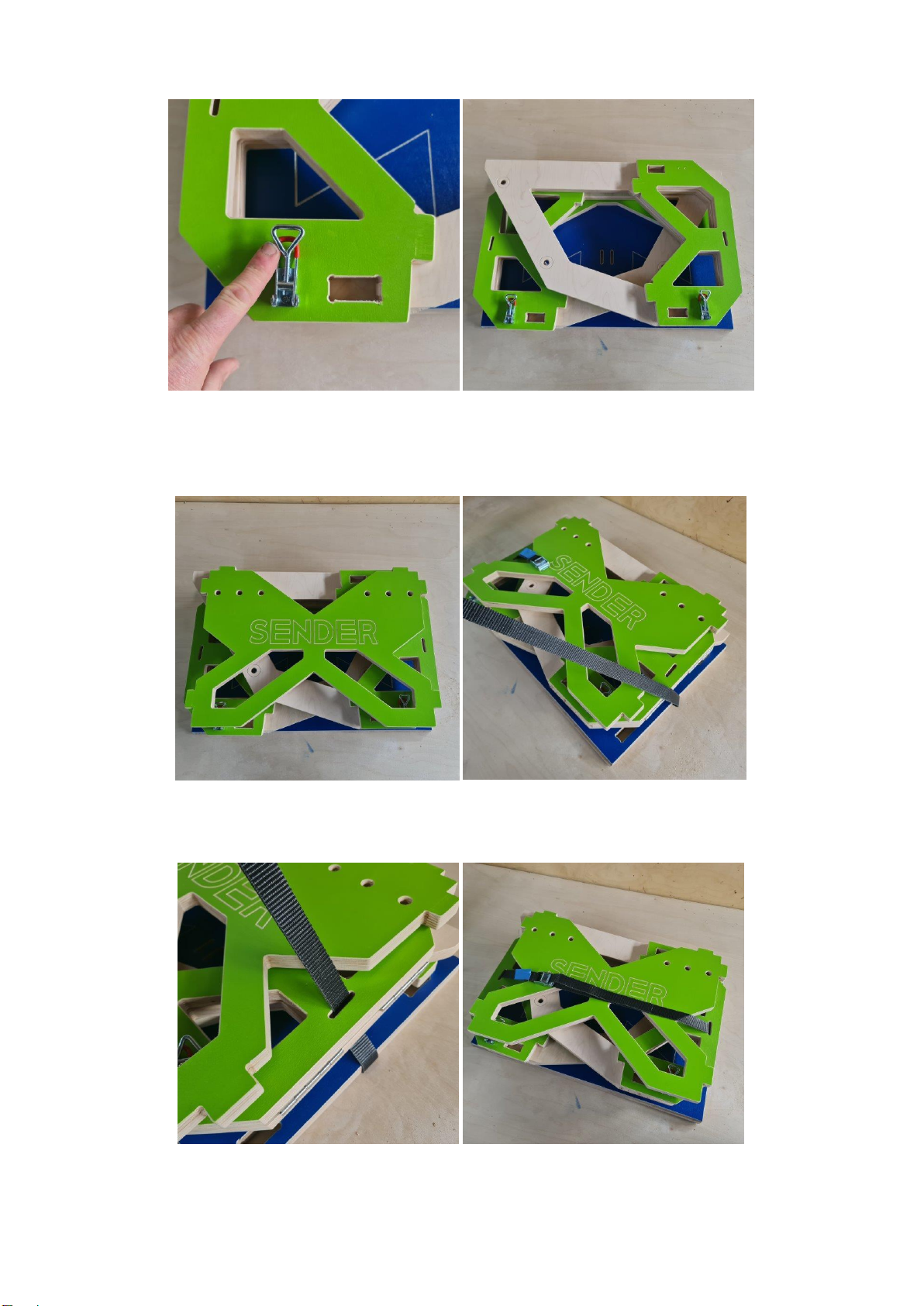
PLEASE NOTE OUR NEW ADJUSTABLE TOGGLE LATCH CLIPS!
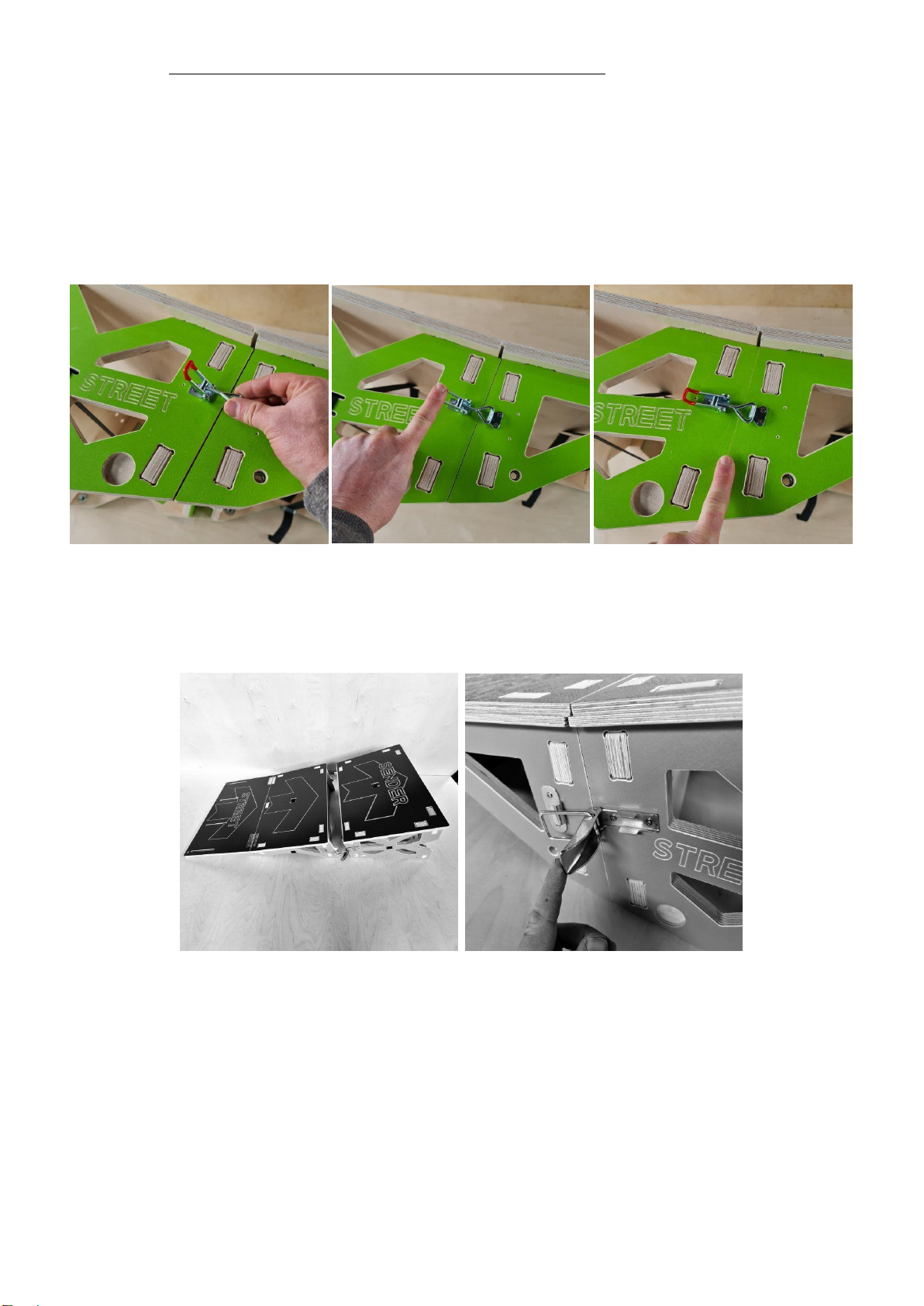
These new clips vary slightly from those in some of the assembly images below! The NEW clips allow you to increase
or decrease the tension of the clip as shown in the image below. IT is extremely important that the clips close under
the pressure of ONE finger! Excessive force will RIP THE SCREWS from the plywood. There is NO NEED for these clips
to be too tight!
IMAGE 1: Turn the HOOK clockwise to tighten ½ turn OR anticlockwise to loosed ½ Turn
IMAGE 2: The correct tension is when the CLIP closes using ONE finger.
IMAGE 3: Shows the clip and join between components closed –NEVER FORCE the clips. ALIGN the components –
adjust the tension –SECURE with EASE!
IMAGE 1 LEFT –IMAGE 2 CENTRE –IMAGE 3 RIGHT
ATTACHING AND SECURING YOUR 200 to 350 High
RAMP SECTIONS
You could EASILY rip the clips off the sides of the ramp if the parts are not properly aligned. DO NOT USE the clips to
haul / force the sides into place. These clips should snap closed easily with one finger when the components match.
The Ramp surface on the 350 High Section fits underneath the 200 High Section.
You have now created a 350 High Jump Ramp –See Skate Plate fitting instructions below if you have purchased one!
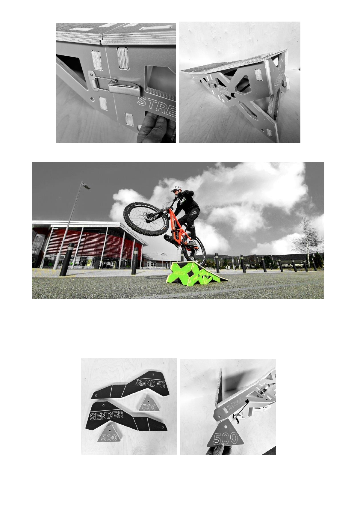
CREATING A 500 mm HIGH JUMP RAMP
STAGE 3:
Take the two triangular front legs and longer back legs. Rest your 350 High Ramp on its side. Take the first front leg
marked with 500 and hold this above the hole at the lowest end of the ramp.
These triangular feet have a specific side. On the back face of the feet is a stepped section. You can easily assess the
correct location for each foot by sitting the foot at the end of the ramp and seeing if the holes and step line up. Take
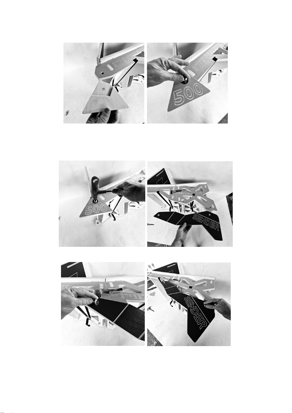
an M10 x 40 Button Head Bolt and Large Washer and place this through the foot into the T nut in the side
component. ALWAYS locate bolts into T Nuts by finger first to avoid cross threading. You should lubricate the bolts
regularly to make this process easier.
Tighten the bolt with the 6 mm Hex Key. Take one of the Long Legs. Examine the non-coloured face as this also has a
long stepped section and small circular peg. This peg is placed into the hole on the side of the ramp. The step sits
UNDER the sides of the ramp. IF the ramp is damp or has not been dried properly these parts may be tight. The
tolerances are small to ensure maximum strength. Dry the parts and try again.
Take two more M10 x 40 mm Button Head Bolts with large washers and locate these in the T nuts by finger first.
Tighten with the 6 mm Hex Key. Repeat the process on the other side. There are now many components that make
your 500 High ramp. You should always check the components are secure BEFORE jumping. See Skate Plate fitting
instructions below if you have purchased one!
STORAGE AND TRANSPORT MODE
There are many ways to interlink the components for transport. Please use this guide as one of the ways to store and
transport your ramp. The Street ramp can be made into a rudimentary rucksack using the strap provided and this is
described below. However, you can purchase a much more comfortable Vinyl carry bag with proper 50 mm Rucksack
straps.
Although the ramp is only 18 kgs. Please assess the suitability of transporting the ramp safely to a location on your
child’s back and their ability to build the ramp.
LEVEL 1 and 2: L1: The Hinged Surfaces / Deck –L2:The Large SENDER X Back Plate
LEVEL 3 and 4: L3: The Lower Side Components –L4: The Right Upper Side Component Colour Face Up!
Level 5 and 6: L5: The Left Upper Side Component Colour Face Down! Plus Feet –L6:The 500 Legs
L6: THIS IS A GOOD STAGE TO PLACE AND TRAP THE COTTON BAG IN THE LAYERS!
Level 7 and 8: L7: The 200 Front Brace and 200 Back Brace –L8:The 350 Front Brace.
Level 9: L9: The Top Surface / Deck
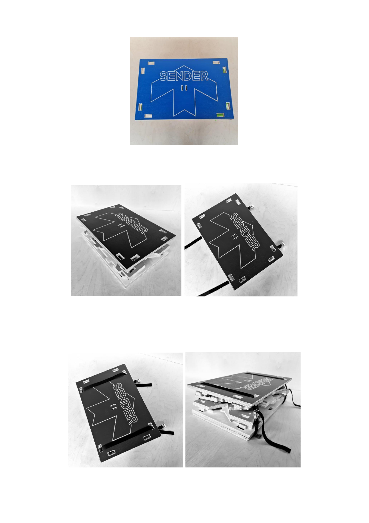
STRAPPING THE COMPONENTS FOR TRANSPORT
Take the Straps and place them under the bottom Hinged Surfaces / Deck with the Cam Buckles placed as shown.
Thread the straps through the slots on the Top Surface / Deck as shown below, and connect the strap to the Cam
Buckles. First take the slack out of both the straps equally. THEN pull each strap as tight as possible to trap the
components. You should always check that the components (especially the triangular feet) are trapped within the
structure and will not fall out in transit and become lost! You should also make sure you have all of the bolts,
washers and hex key.
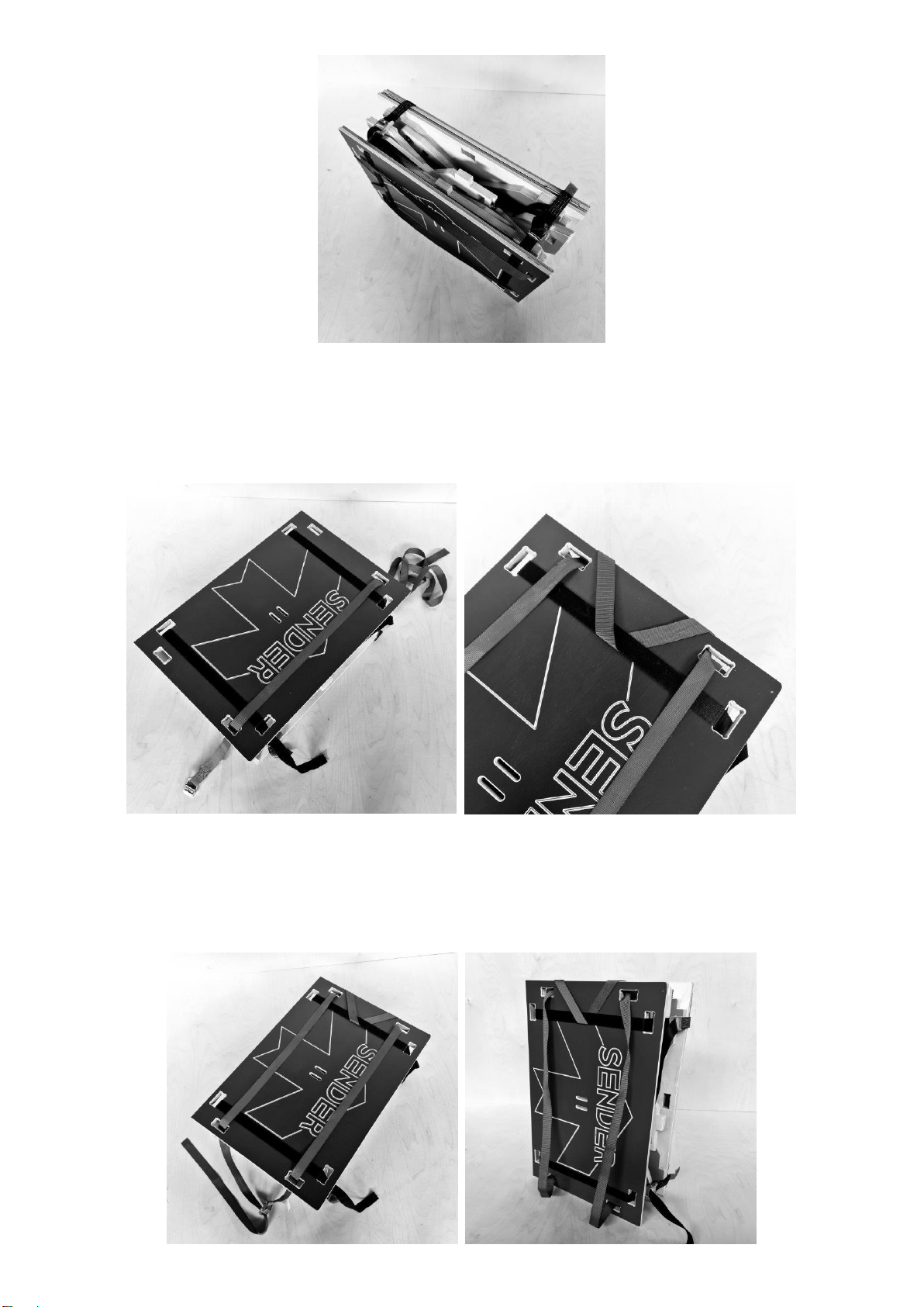
CREATING A RUCKSACK WITH THE EXTRA STRAP
Rotate the Ramp into a Portrait position. Place the Long Strap through the bottom hole and then through the
opposing top hole. Thread the strap over the top edge of the ramp and under the cross strap. Go back over the top
edge of the ramp and back through the hole.
Thread the strap through the opposing hole at the bottom and then thread the end of the strap through the cam
buckle. This creates a rudimentary rucksack. You can adjust the length of the shoulder straps at the cam buckle. It is
easier and safer to mount the ramp onto your back if a partner lifts the ramp up so you can thread your arms
through the straps. The straps can slide quite easily so be careful not to lose control when lifting the ramp. Please
also be careful to ensure the ramp is high enough on your back to avoid catching on your rear wheel whilst pedalling.
PLEASE NOTE!
You may want to trim the straps with a hot knife. Do not cut the strap with scissors or it will fray and may not reseal
properly making it difficult to thread through the Cam Buckle. Please make sure you leave enough strap (approx. 200
mm) to enable the strap to be threaded with ease and provide a handle to pull the strap tight.
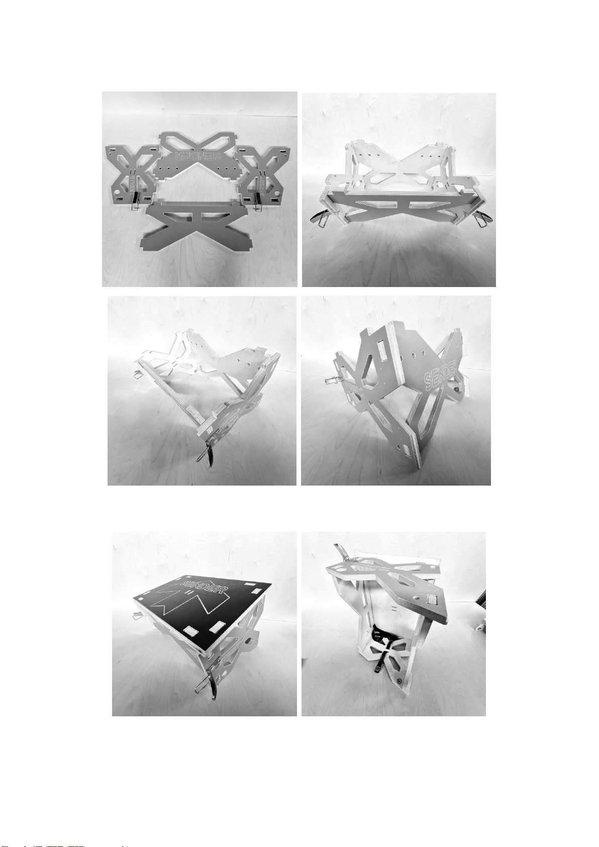
BUILDING AND INSTALLING YOUR L2 RAMP
EXTENSION
The L2 (Level 2) Extension is an Optional Extra that you may not have purchsed with your L1 (Level 1) Ramp. This
Extension allows you to SUPER SIZE your take off to 750 mm HIGH.
INSTALLING THE CLIPS
IF YOU PURCHASED YOUR L2 ramp seperately / after your PURCHASED your L1 Ramp you may need to install the
CLIPS. Please follow the instuction below to complete this process BEFORE asssembling the Substructure!
ASSEMBLING THE SUBSTRUCTURE
If you purchased your L1 and L2 together the clips may already be installed. Check and proceed if they are already on
the L1 and L2. If not complete the stage above.
The coloured faces should be on the outside. Unfold the hinged components. Push the Large X shaped component
into the hinged sides. Take the smaller brace and push this into the slots in the sides. You have now created the
substructure.
Take the Ramp Surface and place this over the substructure. The surface has holes that go all the way through the
surface and some additional pockets on the back face. You may need to square the substructure ensuring that the
substructure parts are properly in place. When the Surface is aligned with the substructure a firm push should locate
all parts securely.
It is important to note that the ARROW on the Ramp surface points to the Top edge of the ramp. The Top Edge / END
of the ramp is the end with the LARGE X Shaped plate as shown below!
The Substructure and Surface are secured in a similar way to the components on the L1 Ramps. Take the strap
supplied and thread this through the bottom slot from the inside! Pass it back through the oposing slot on the
otherside of the hinged join. Pass the end of the strap through the slots in the ramp surface so the strap comes back
to the inside.
Pass the strap through the slots that cross the join on the other side of the ramp. Thread the Cam Buckle and pull
firmly to add tension. Turn the extension upside down onto its surface. Check that all the parts are together and pull
firmly to add extra tension.
JOINING YOUR EXTENSION TO YOUR L1 in 500 mm HIGH
MODE
Lift the L2 Extension and place it carefully against the L1 in 500 High Mode. The Ramp Surface should should fit
UNDER the surface on the L1.
Check the TENSION in the Clips. When the L1 and L2 Ramps are properly aligned the CLIPS should close with ONE
Finger. IF they are too tight unwind the HOOK –If too Loose wind the HOOK to add more tension. ½ a turn is
normally more than enough. NEVER force the clips or you could rip the screws from the plywood.
Check the TENSION in the second clip and secure this when it is correct. Repeat this on the otherside to complete
the process of attaching your L1 Ramp to L2 Ramp Extension.
Always check the clips, bolts and straps are secure BEFORE Jumping!
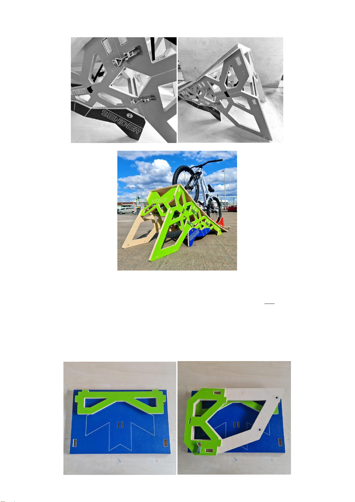
STORAGE AND TRANSPORT MODE
There are many ways to interlink the L2 components for transport. Please use this guide as one of the ways to store
and transport your ramp. The L2 Extension should NOT be attached to the L1 and placed into rucksack mode using
the strap provided. However, you can purchase a much more comfortable Vinyl carry bag with proper 50 mm
Rucksack straps and the L2 will fit inside this bag and is safer to carry / transport. The combination of ramps is 30 kgs
so extreme care should be taken giving this weight to adults and especially children.
LEVEL 1 and 2: L1: Extension Surface / Deck –L2: Left HINGED Leg FOLDED
LEVEL 3 L3: The Right HINGED Leg Folded –Ensure the Clip is Folded as shown below on both parts
LEVEL 4 and SECURING THE PARTS: L4: The Large X Back Plate –L2: Thread the Strap THROUGH the SLOT on the
LEFT of the X so the CAM BUCKLE sits on top of the X. Place the Strap UNDER the Surface and bring back to the other
side RIGHT of the X.
Thread the strap through the slot on the right of the X. Thread the end of the strap through the Cam Buckle and add
tension to hold the components together.
Place the STACK of components inside the Vinyl Carry Bag if you purchased one.
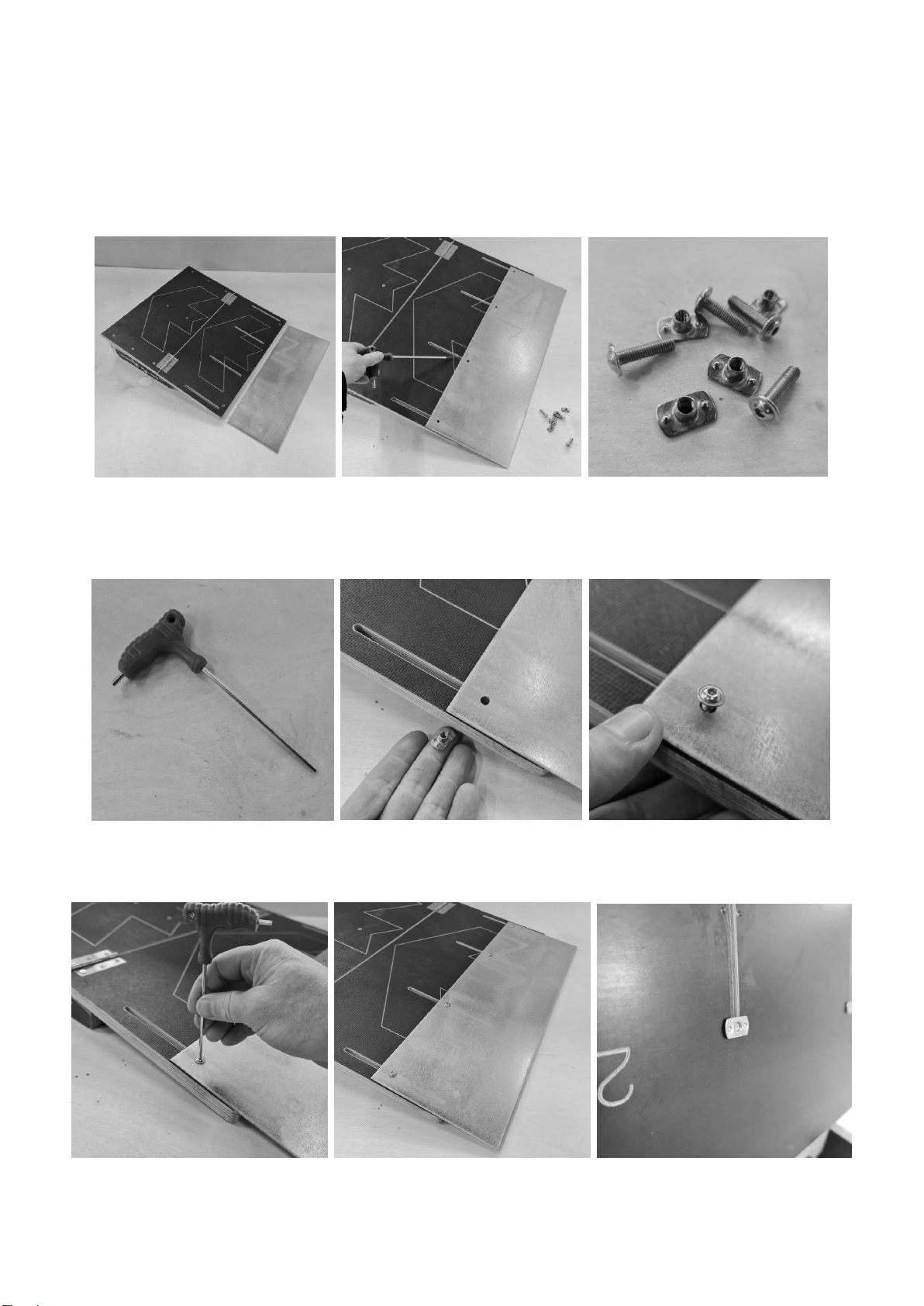
INSTALLING THE SKATE PLATE
This component may not have come with your ramp
The Skate Plate can be installed and removed quickly. However, the Skate Plate is better left on the ramp to avoid
losing the parts. (More can be ordered) You will need a 3 mm Allen Key found on your BIKE TOOL! Place the
Galvanised Steel Plate over the 4 slots on the first ramp surface. Take a small bolt and T Nut.
Place and Hold the T nut underneath the surface inside the first slot. Move the T nut so you can see it through the
first hole in the plate. Connect the Bolt and T Nut together and wind the bolt by finger until nearly tight against the
plate.
Repeat for the remaining 3 x T nuts and Bolts. You may need to manipulate the plate so do not tighten the bolts with
the Hex key at this stage. Please ensure that the T nut is perpindicular to the slot when you look at the smooth back
surface of the ramp for full strength. See far right image below.
Adjust the plate by sliding it up and down the slots. The plate is in the correct place when the edge is on the ground
and flush with the face of the ramp. IMPORTANT! You will need to move / adjust the plate EACH Time you change
the height and Transition of the ramp
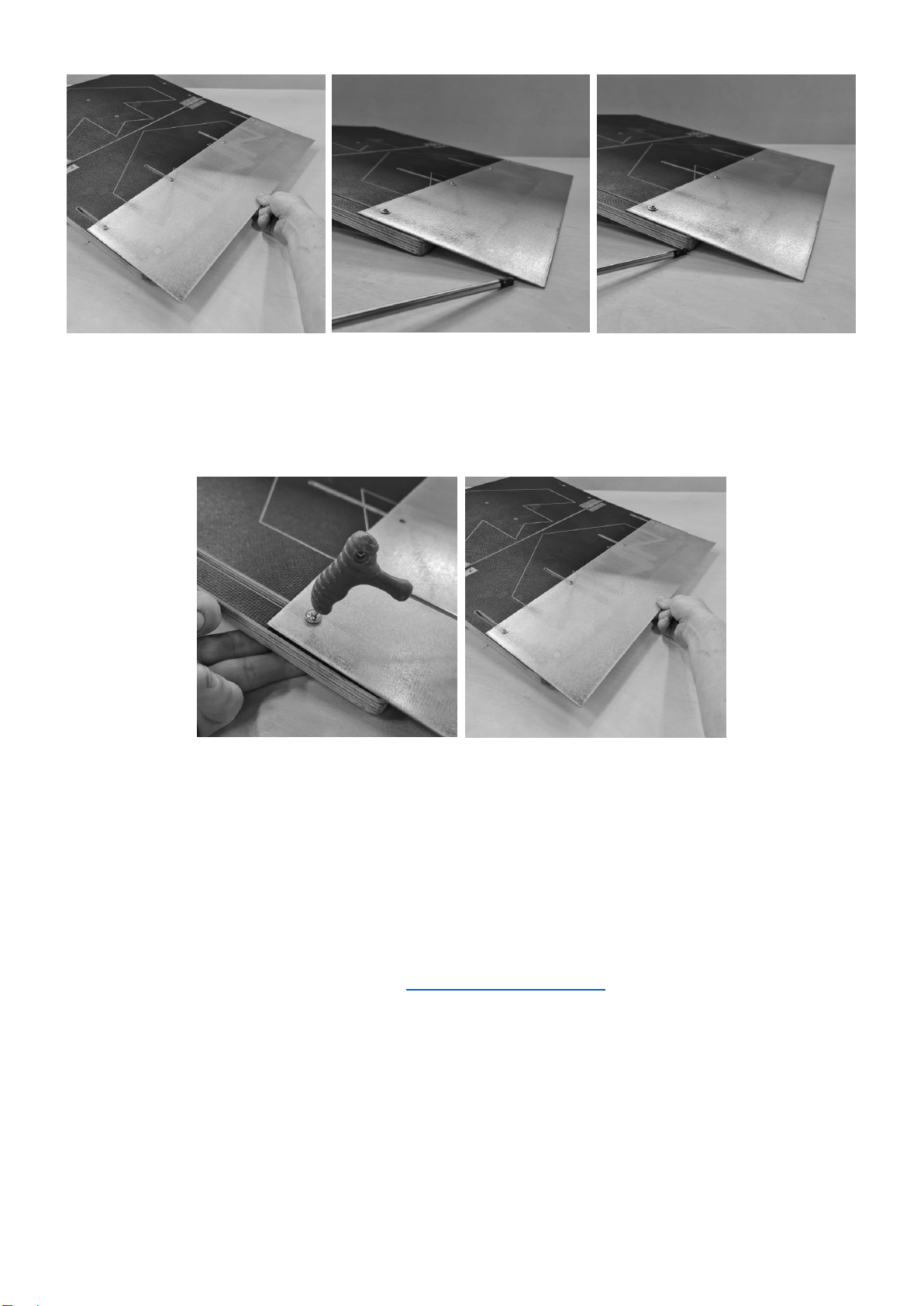
Once the position is correct tighten the bolts to prevent movement / slippage. When you are finished with the ramp
the plate can slide back into storage mode. Simply untighten –slide and retighten the plate. Be careful not to scratch
the ramp surface.
IT IS EXTREMELY DANGEROUS TO RIDE OR MOVE THE RAMP WITH THE SKATE PLATE PROTRUDING.
TREATING YOUR RAMP!
Please remember to coat your ramp with a CLEAR preservative. Be aware that even clear preservative can darken
the colour of your ramp so trial one of the lower braces / batons first. NEVER USE VARNISH!
Spray your bolts and T Nuts regularly to make placement and removal easier!
REPLACEMENT PARTS!
HAPPY LANDINGS!
Remember to wear your Helmet, Gloves and Knee Pads and Jump in a Safe Place
This manual suits for next models
1
Other SENDER RAMPS Bicycle Accessories manuals


Popular Bicycle Accessories manuals by other brands


Specialized
Specialized Elite CylcoComputer user manual

Sigma
Sigma BC 16.16 manual

Playcore
Playcore Dero Setbacks installation instructions

VDO Cyclecomputing
VDO Cyclecomputing x3dw instruction manual

Cateye
Cateye RAPID X2 manual

buratti meccanica
buratti meccanica Clorofilla Trail Use and maintenance manual


