SENDER RAMPS X MINI KICKER User manual

SENDER PROGRESSION RAMPS
X MINI KICKER
FOOTWEAR: VICE - BIKE: STITCHED 720
Thank you for buying a SENDER X MINI KICKER RAMP. This is our entry level height adjustable and portable skate, scoot and bike
ramp. Build confidence with ease by gaining height in small increments 175 mm to 250 mm High! Please follow these
instructions carefully for your safety.
MODULAR:
This Ramp can be used with our other features but is not designed to be modular or bolt onto any other components. The X
ramp is a standalone mini kicker. The next level of ramp to consider is the ROOKIE or CORE 200. Both are Modular with our
range and system.
FOR ENVIRONMENTAL REASONS WE DO NOT SUPPLY SINGLE USE 6 mm / 3 mm ALLEN
KEYS - THESE ARE COMMONLY FOUND ON BIKE AND SKATE TOOLS!
SAFETY FEATURE: The front edge of the ramp has 2 x PEG POINTS so that you can add extra security when using the ramp on
grass or gravel. These points must be used if you attempt to Back Flip the Ramp. These cannot be use when the skate plate is
attached. The skate plate is not necessary of you only intend to use a bike.
SUITABLE FOR SKATEBOARDS and SCOOTERS
The X Ramp has an adjustable SKATE PLATE. This Galvanised plate moves to meet the angle of the ground. PLEASE SEE
INSTRUCTIONS LATER IN THIS GUIDE
RAMP WEIGHT / RANGE / ADJUSTMENT + MARKINGS:
The X Ramp has a Straight Transition / Surface
It can be adjusted in 25 mm increments from 175 mm to 250 mm
Transition Length on the X Ramp is 750 mm
The X Ramp fully assembled with skate plate weighs 8.3 kgs
SAFE OPERATION!
Once you are familiar with all the parts you can set up, fold and pack the X Ramp in 5 minutes. You can easily adjust the ramp to
YOUR CHOSEN height in a matter of minutes. However, YOU MUST ALWAYS check the components are bolted tightly together to
prevent the ramp from failing / folding or collapsing BEFORE each use. Lift your ramp into place with two people if necessary.
Dragging the ramp will damage components.
DESIGNED FOR:
Riders, clubs and coaches on all types of skateboards / scooters and bikes - Heavy use including E Bikes.
Safe Working Load is 150 Kgs –Dynamically Tested to over 300 Kgs
M10 Bolt Torque setting is 12 Nm

SAFE USE AND PPE:
Always wear a full face helmet, gloves and knee pads when jumping. We also recommend back protection and a neck brace. You
should not jump ramp to ramp with a gap between components. X Ramps can be landed to FLAT. However, it is better to use a
grass downslope as the height increases or a landing ramp. Ensure adequate fall space all around with no surrounding impact
surfaces like fences, trees, vehicles or roads. Keep spectators clear. Locate your ramp on flat even ground. Take your time and
follow all the user instructions carefully for max strength. Built confidence before trying higher jumps. We recommend hiring /
consulting a coach to improve skills. When jumping goes wrong it can lead to life changing injuries and destroy expensive bikes /
skateboards and scooters.
SENDER BUILT TO LAST:
Designed and Manufactured in the Highlands of Scotland from 18 mm (13 layer) Birch Plywood and 18 mm (13 layer) Phenolic
Grip (mesh) coated Plywood secured with Steel Components. Look after your ramp and it will last a life time. We recommend
storing the ramp inside after use and carefully drying the ramp if it is used outside in the damp or rain. Spare parts are available
for purchase on request. The Plywood has been Independently Impact tested and Insert Pull Tested. Do not drag or pull the
ramp around. It should be LIFTED into place to prevent premature deterioration.
PRESERVING AND MAINTING: NOTES ON COLOURED RAMPS AT THE END OF INSTRUCTIONS
When you assemble your ramp please use silicone spray to protect and lubricate the bolts. Follow instructions on the bottle /
can for safe use. Preserve your ramp BEFORE use with the recommended Decking Protector –please see the end of the
Instructions for Brand and type (Natural or Clear).
Torque Wrench (recommended to tighten bolts for exact setting) –Spray your bolts during assembly
process and as often as possible for better function
Moving parts such as Nuts and Bolts should be silicone sprayed frequently. All cut edges and natural plywood faces should be
treated with LOW VOC (Water Based) Decking protector Natural Colour. Repeat annually. Under no circumstances use Varnish!!
Check for damage before and after each use and retire the Ramp if you find any until you seek further advice from
support@sender-ramps.com. Additional notes at the end of this guidebook.
INSTALLATION EQUIPMENT REQUIRED:
1 x 6 mm HEX KEY (Found ON Your Bike Maintenance TOOL!) –SUPER Fast with an Impact Gun with 6 mm Attachment.
A 3 mm HEX KEY for tightening and loosening the small Skate Plate bolts
A Torque Wrench will ensure that ALL bolts are set at the max tension of 12 Nm
Your ramp may come unassembled or assembled. Please reads the section / stages appropriate to your purchase.
FOR ENVIRONMENTAL REASONS WE DO NOT SUPPLY SINGLE USE 6 mm / 3 mm ALLEN
KEYS - THESE ARE COMMONLY FOUND ON BIKE AND SKATE TOOLS!

X MINI KICKER ASSEMBLY
COMPONENTS:
STEEL SKATE PLATE –BACK PLATE –SUPPORT STRUCTURE
HEIGHT ADJUSTMENT PLATE –FRONT OF TRANSITION (SURFACE) –REAR OF TRANSITION
FIXINGS
VERY IMPORTANT:
STAINLESS STEEL IS SOFT. It is VERY easy to round the heads of screws. Apply CONSTANT PRESSURE when fixing components.
Take your time to complete the ASSEMBLY process. Poor Assembly WILL lead to a weak and poorly functioning product!
ASSEMBLY TOOLS:
1 x 6 mm Allen HEX key
1 x 3 mm Allen HEX Key
1 x Pozi 2 Hand Screw Driver (Your model may already have the T nuts installed)
Wear appropriate PPE when assembling your product –Eyewear / Gloves / Footwear. Protect your work space to avoid
damaging your property.
X MINI KICKER FIXINGS:
4 x 10 x 35 Countersink Bolts
6 x 10 x 50 mm Countersink Bolts
2 x 10 x 40 Button Head Bolts
2 x Large Washers
1 x Strap
1 x Steel Skate Plate
3 x Small Plate Bolts
3 x Small Plate T Nuts
ASSEMBLING YOUR RAMP
STAGE 1: Time to assemble approximately 30 Minutes
Your model may already have the T Nuts Installed. If so, move onto the next stage.
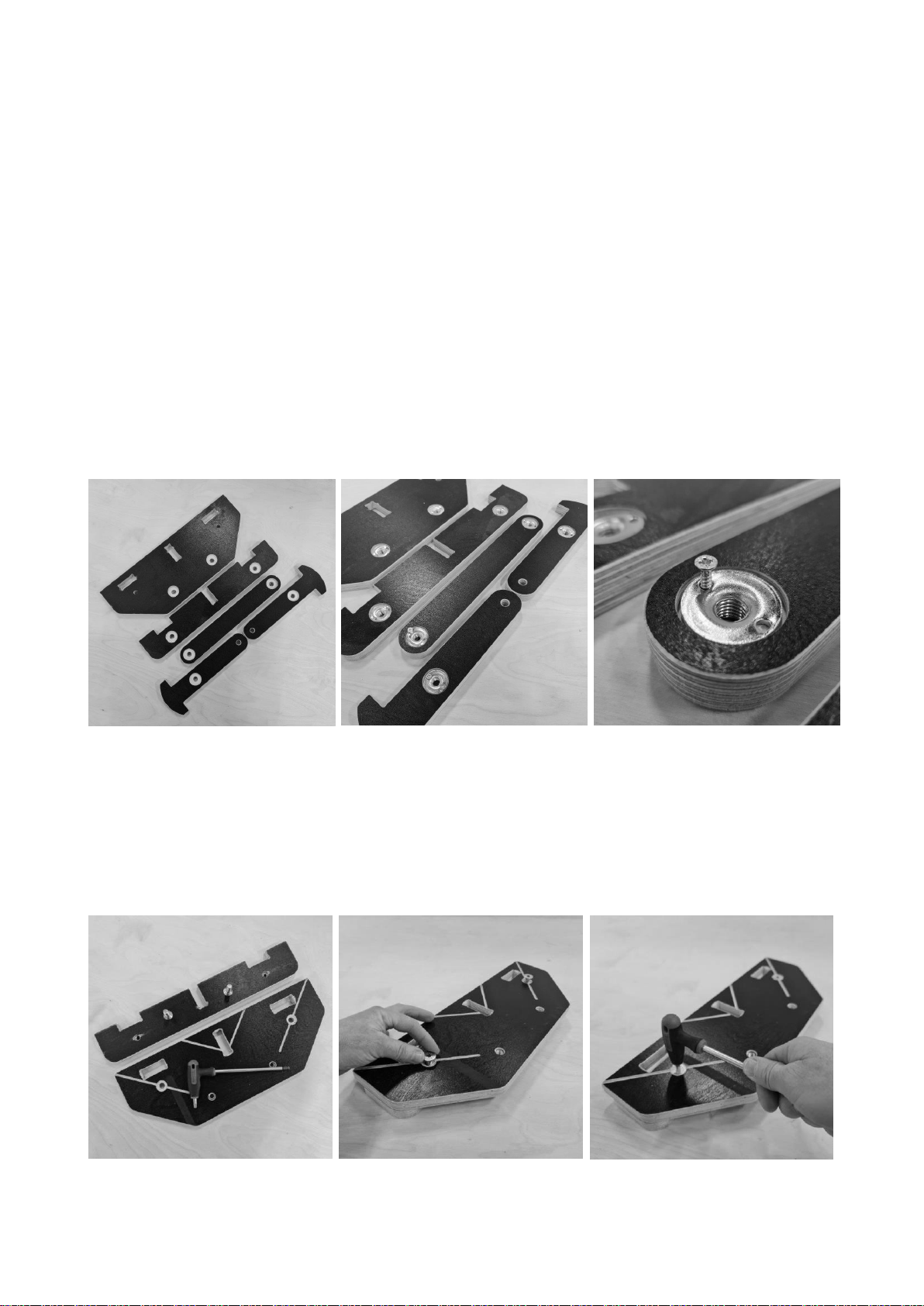
Select all the components with large pockets on the plywood surface that have a 13 mm “through”hole in the middle of the
pocket. See image below! Place the T nuts into these pocketed Holes ONLY!
Place the Small Screws into the holes in the T Nuts and fix them to the Plywood. The Screws MUST be placed VERTICALLY!
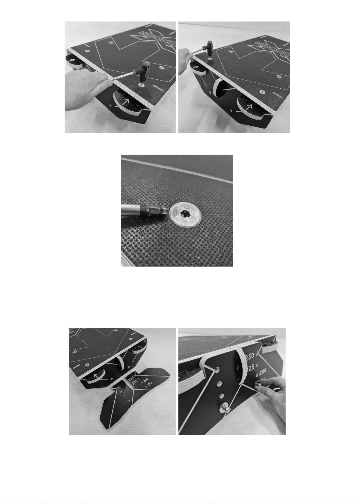
STAGE 2:
Take the 2 x Back Plate components as shown. The Large plate with the rectangular pockets sits on top of the smaller “Toothed”
component. Align the holes and use an M10 x 35 mm Countersink Bolt to hold these parts together. You should always catch the
thread of the bolt and T Nut using your fingers BEFORE tightening with the 6 mm Allen Key. This will prevent Cross Threading!
Make sure the 6 mm Allen key is fully in the socket of the bolt (this will prevent you rounding the hex head). Turn this bolt until
it is flush. 12 Nm is the recommended torque setting. You must check these bolts regularly so they remain secure.
The Left Image shows the Countersink Bolt pulled tight and flush with the face of the plywood. The RIGHT Image below shows
the rear face of the back plate once the two components are bolted together.
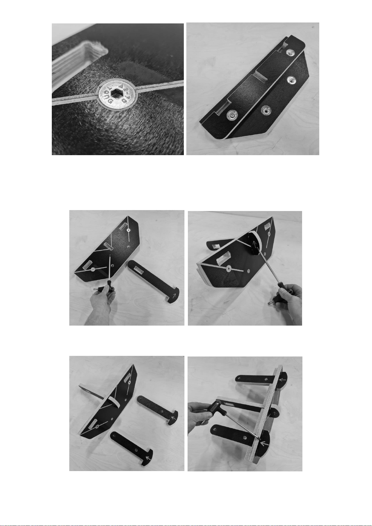
STAGE 3:
Take the Back Plate and the substructure component with the rectangular slot and arrow pointing perpendicular to the long
arm. Push the arm into the CENTRAL Slot in the Back plate until the “T”is Flush. The arrow should be pointing UPWARDS as
shown below
Take the two substructure components that have an arrow pointing along the arm. Place these through the back plate until the
“T”is Flush. The Arrows should be visible on TOP of the Back Plate as shown.
Take the straight substructure component with 2 x T Nuts and pass this through the slot in the CENTRAL arm. The T Nut should
be on the UNDERSIDE of the substructure. This is VERY IMPORTANT for the Strength of your Ramp.

IMAGE BELOW SHOWS THE CORRECT LOCATION OF THE T NUTS IN THE ARMS AND CROSS BATON FROM
BELOW (The structure has been turned over)
STAGE 4:
Place the Ramp Surface onto the Substructure. Take 2 x M10 x 35 Countersink bolts and place these through the surface nearest
the TOP EDGE of the surface into the T Nuts in the arms below. This might be easier with the help of another person! Catch the
thread with your fingers first then use the 6 mm Allen key to wind the threads into the T nuts. DO NOT TIGHTEN THE BOLTS AT
THIS STAGE. Tightening will make it harder to locate the next two bolts!
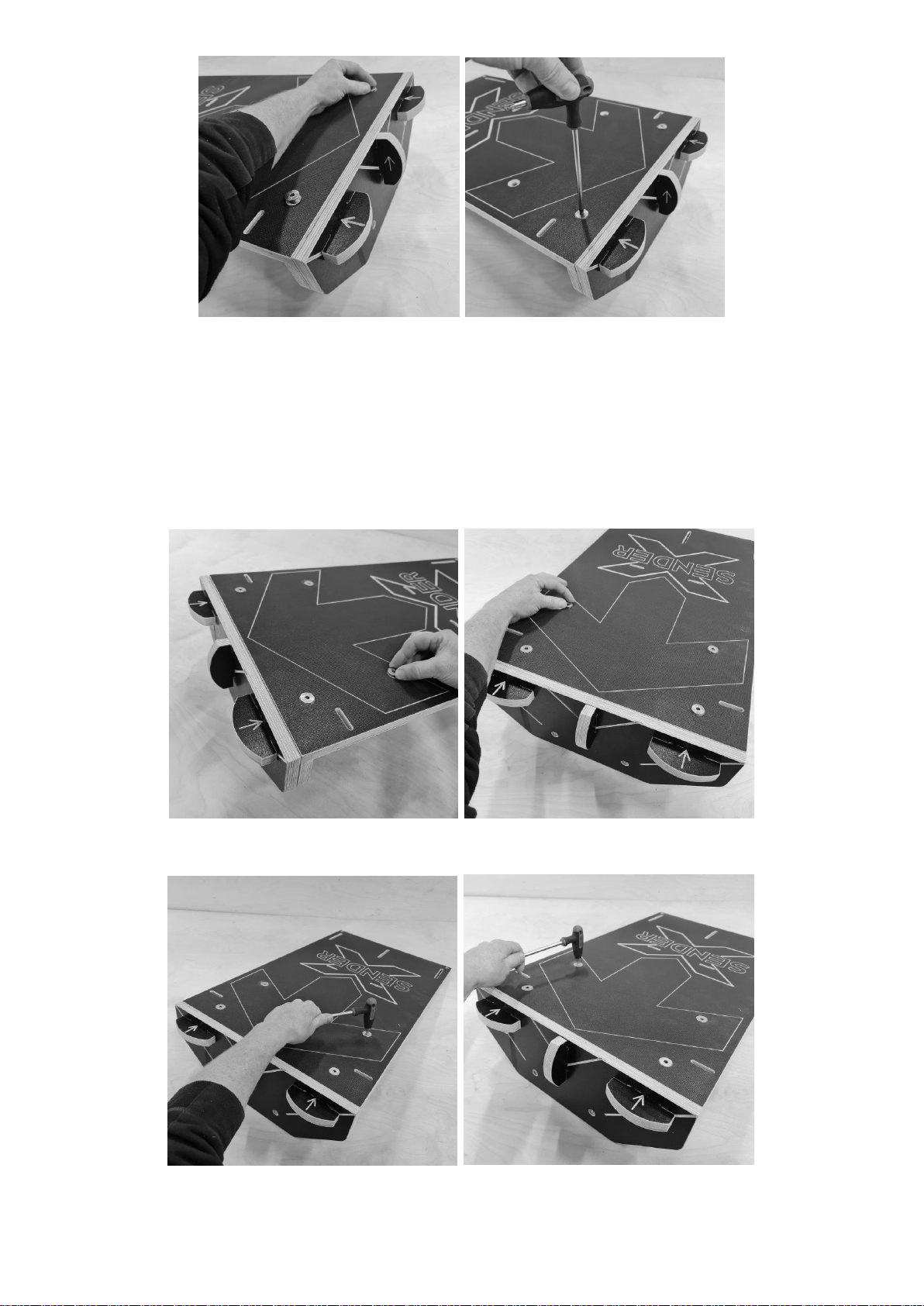
STAGE 5:
Take 2 x M10 x 50 Countersink Bolts and place these through the surface as shown below. You may need to manipulate the
cross baton below the surface to align the T Nut and Bolt. You must catch the thread using your fingers first. Do not use the
Allen Key until you have aligned and caught the thread on the 2nd Bolt and T nut. Once you are sure they are both attached and
not cross threaded use the 6 mm Allen key to tighten the bolts.
Before tightening these bolts turn the ramp over so you can see the bottom face. Make sure that the central Arm sits in the
Groove / slot in the plywood.
Turn the ramp back over and Tighten the bolts to 12 Nm –The bolt heads should be flush with the surface.
Complete this stage by tightening the two bolts nearest the end of the ramp to 12 Nm.
The image below shows the Countersink bolts flush with or slightly below the surface.
STAGE 6:
Next! Install the Height Adjustment plate. Place this in front of the back plate as shown. Take 2 x M10 x 40 BUTTON HEAD Bolts
and 2 x Large Washers. Sit the Adjustment plate against the back plate. Use the two holes marked as 175 mm if you would like
the ramp at this height OR select a different height setting. Fix the Adjustment plate with the two bolts and washers. Tighten
both to 12 Nm. The height can be increased in 25 mm steps.

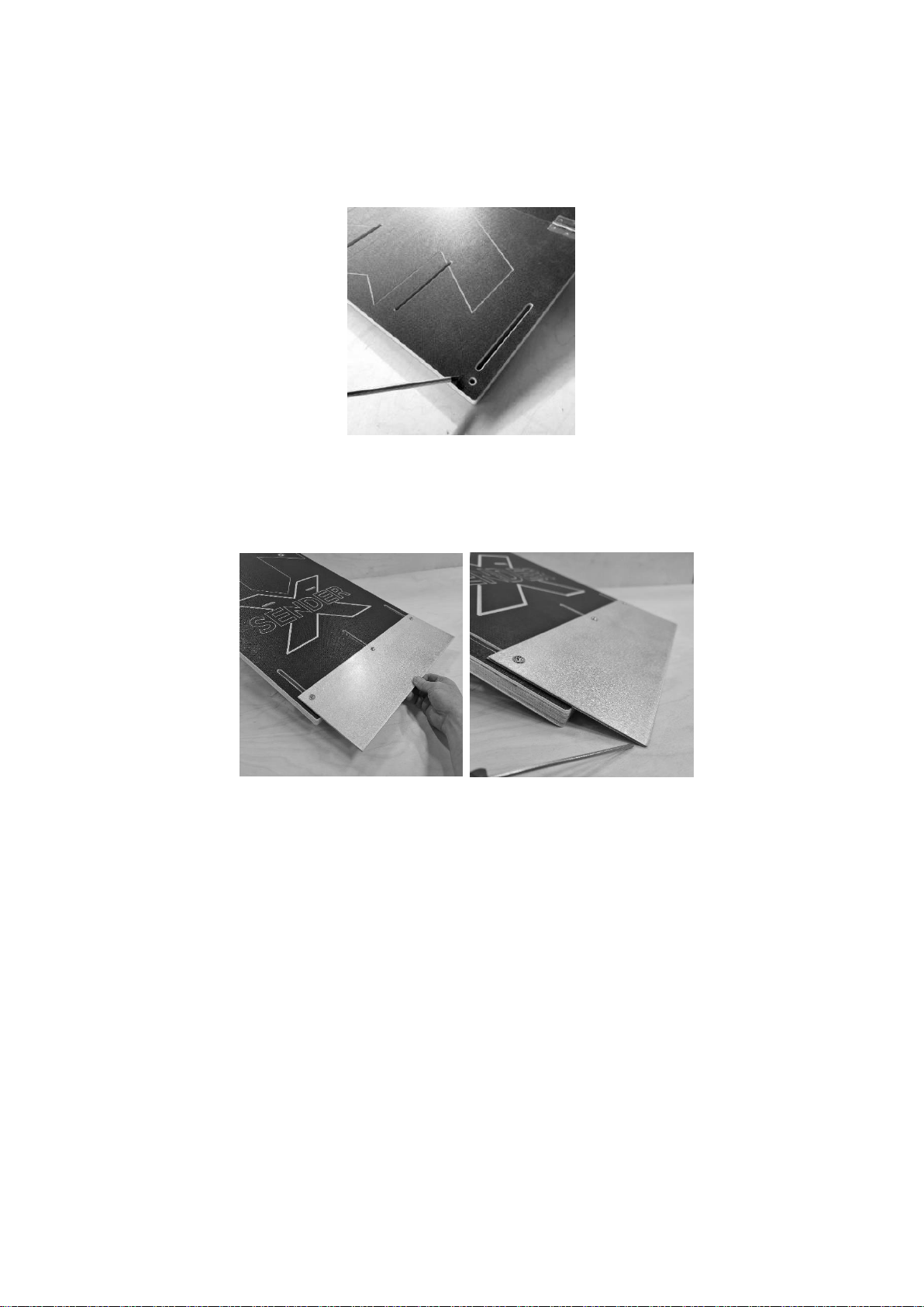
STAGE 7: INSTALLING AND ADJUSTING THE SKATE PLATE
You must use both of your skate plates at the same time for maximum strength. Before placing them onto the ramp make sure
that the holes align. They have been drilled as a pair. You may have turned them during unpacking and they no longer align
perfectly. Flip until you get a good hole match / alignment.
Take one of the small T Nuts. Place this into the slot in the ramp nearest to you. Slide the nut down the slot until it is below the
holes in the plate
It is easier to install the bolt into the T Nut if the plate is not sliding back down the ramp surface. Find the best location where
the plate is resting on the floor and will not slide. Push the bolt through the two holes in the plates and wind the bolt into the T
Nut by finger first. One you locate the thread use a 3 mm Allen key to engage more of the thread. Do NOT TIGHTEN Yet!

Repeat this process at the second and third slot. You should be able to slide the plate up and down the surface. Be careful not to
scratch or mark your surface with the edges of the plate.
When the ramp is at the top of the slots it is in storage and transport mode. You should always tighten the bolts to hold it in this
position. Especially if you are taking your ramp on your back to a park in rucksack mode. A protruding plate is a severe hazard
that could cause serious harm if you fall or are taking the ramp off your back and hit another person as it travels to the ground!
The skate plate should always be adjusted to meet the ground. The plate will need to be reset every time you change the height
of the ramp! Simply loosen the bolts so you can slide the plate. Make sure the wooden surface is flush with the ground. Make
sure the plates are touching the end of the wood and the ground. Tighten the bolts to hold this position.

When you tighten the bolts, the T Nut on the back face should be perpendicular to the slots for maximum strength as shown.
STAGE 8:
Your ramp is now ready for use. Before each use check the ramp and plate for damage. Always check
and tighten all the bolts on the ramp. A torque wrench will ensure your bolts are always at the correct
setting.
INSTALLING THE RUCKSACK / CARRY STRAPS
Unwind your strap. The ramp has 4 slots to create a rucksack and allow you to carry your ramp.

Stand the ramp on its end with the skate plate at the top. Starting from the back face at the bottom left hand slot (as you look at
the ramp surface) push the webbing through the slot. Pull the slack through until you are only 50 mm from the sewn section.
Feed the webbing back through the top left shoulder slot. Keep the webbing neat and flat (without twists).
Pull the slack through and pass the webbing through the next shoulder slot from the back face of the ramp. Pull the slack
through and pass the webbing through the bottom right hand slot.
At this point you can adjust the amount of slack to give you bigger shoulder straps. Pass the webbing through the cam buckle
behind the ramp.
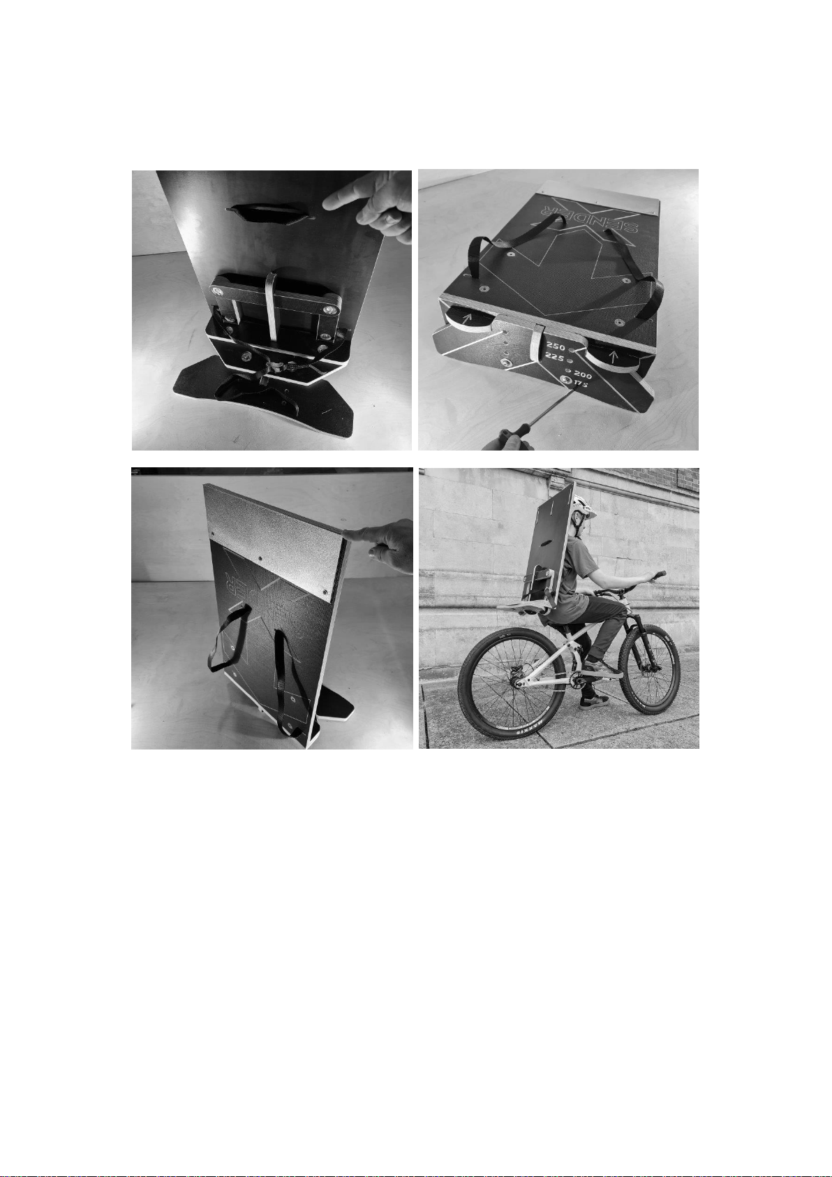
Make any final adjustments by paying out extra webbing or taking some in. You may have to slide / adjust the webbing behind
the ramp at the top strap slots. We recommend transporting the ramp on your back when the height adjustment plate is secure
at 175 mm (Lowest setting). This reduces the amount the ramp protrudes and reduces leverage on your shoulders.
FINALLY! Make sure the skate plate is in storage mode. This is important as a protruding plate could be extremely dangerous to
yourself and others as previously described.
IMPORTANT! PRESERVING RAMPS + COLOURED RAMPS:
BLUE COLOURED RAMPS MUST BE TREATED WITH RONSEAL LOW VOC WATER BASED DECKING PROTECTOR –NATURAL or
CLEAR! This will seal and maintain the blue colour. You should apply the preservative carefully onto these blue surfaces allowing
the coating to soak into the wood. Coat all cut edges twice. If you do not coat the blue surfaces you may experience loss of
pigment when the ramp is wet. Coating / preserving any of the coloured ramps, especially blue with the natural colour may
change darken the appearance of your ramp.
On ALL other colours you should coat all cut edges twice but run a test on an internal coloured part to check the discolouration!
BEFORE committing to coating the coloured faces just in case you do not like the darkening effect.
NATURAL WOOD / PHENOLIC MESH PLYWOOD / COLOURED PLYWOOD.
It is not essential to use a preservative (except on blue) but it will greatly increase the longevity of your ramp and prevent
unsightly marks or reduce the chance of mould. The water based preservative we recommend is very easy to apply but you
MUST use a wet and then dry cloth to remove the excess from ALL BROWN PHENOLIC Surfaces. It leaves a waxy film that peels
in the rain! You should coat / treat all cut edges, all birch faces and any holes / routered text. Preferably twice! And again
annually or biannually. The Natural preservative DOES darken the birch but does not YELLOW the wood. Ronseal does come in a

clear version and this is recommended if you have a coloured ramp. Oil based preservatives that get onto the Phenolic plywood
may create a very slick and dangerous surface.
DISPOSING OF YOUR RAMP
You should remove all screws / nuts and bolts and place these in metal recycling. You must put the plywood in the wood
recycling. BETTER! Get in touch for new parts or one of our refresh kits! You can keep using the ramp or even sell the ramp to
another user. This is by far the MOST ENVIRONMENTALLY FRIENDLY SOLUTION.
Thanks again –We hope you enjoy the process of building your ramp and then making fast progress to new skill levels and
greater confidence on the trail!
Scott and Team
You can get expert advice at Sender. Do not hesitate to contact us. You can also order replacement parts. This keep your
purchase environmentally friendly and keeps you rolling.
Please subscribe to our YouTube Channel Sender Ramps for notifications when we upload new films. If you need advice or help
please contact us direct support@sender-ramps.com
Table of contents
Other SENDER RAMPS Bicycle Accessories manuals


Popular Bicycle Accessories manuals by other brands


Specialized
Specialized Elite CylcoComputer user manual

Sigma
Sigma BC 16.16 manual

Playcore
Playcore Dero Setbacks installation instructions

VDO Cyclecomputing
VDO Cyclecomputing x3dw instruction manual

Cateye
Cateye RAPID X2 manual

buratti meccanica
buratti meccanica Clorofilla Trail Use and maintenance manual


