manuals.online logo
Brands
  1. Home
  2. •
  3. Brands
  4. •
  5. Seneca
  6. •
  7. Cash Counter
  8. •
  9. Seneca S502-80 User manual

Seneca S502-80 User manual

ATTENZIONE!
L’installazione, la configurazione del circuitoin cui è inserito il dispositivo e la sigillaturadei coprimorsettideve essere eseguita
da figure professionalmente qualificate. Togliere la tensione prima di intervenire sullo strumento.
WARNING!
Device installation, wiring configuration and terminal cover sealing must be carried out only by qualified professional staff.
Switch off the voltage before device installation.
DIMENSIONI (mm)
SIZE (mm)
MODELLI DISPONIBILI
AVAILABLE MODELS
Nome
Name
Modello/Porta
Model/Port
Inserzione possibile (es. 1.2.1=1fase,2fili,1corr.)
Available wiring (
e.g. 1.2.1=1phase,2wires,1curr.)
Ingr. tariffa
Tariff input
Uscite S0
S0 outputs
Cert. MID
MID cert.
S502-80 IR 1.2.1 1 2
S502-80-MID IR 1.2.1 1 2 •
I contatori parziali sono azzerabili su tutti i modelli.
In all device models partial counters are resettable.
PANORAMICA
OVERVIEW
I
- ITALIANO
Display LCD retroilluminato1.
Tasto multifunzione2.
LED metrologico3.
Morsetti di corrente, tensione,4.
neutro
Sigillo antieffrazione5.
(NON RIMUOVERE)
Porta IR6.
GB
- ENGLISH
Backlight LCD display
1.
Multifunction key
2.
Metrological LED
3.
Current, voltage and neutral
4.
terminals
Safety-sealing
5.
(DO NOT REMOVE)
Porta IR
6.
3
4
6
1
Tariff
5
S0-2 S0-1
2
Il sigillo antieffrazione e la copertura dei morsetti piombabile sono inclusi solo con i contatori certificati MID.
The safety-sealing and the sealable terminal covers are included only with MID certified counters.
SIMBOLOGIA SUL PANNELLO FRONTALE (ESEMPIO)
SYMBOLS ON FRONT PANEL (EXAMPLE)
I
- ITALIANO
Nome dispositivoA.
Certificato di approvazione del tipoB.
Classe di precisioneC.
Simboli di approvazione MIDD.
Temperatura di funzionamentoE.
Numero serialeF.
Data MatrixG.
Costante del contatore (LED metrologico)H.
Classe di protezioneI.
Tipo di collegamento (monofase, 2 fili)J.
Tensione/frequenza nominaleK.
Corrente base (corrente massima)L.
Se il dispositivo è versione NO MID, “Cl.1 EN 62053-21”
sostituirà i campi B, C e D.
GB
- ENGLISH
Device name
A.
Type approval certification
B.
Accuracy class
C.
MID approval symbols
D.
Working temperature
E.
Serial number
F.
Data Matrix
G.
Meter constant (metrological LED)
H.
Protection class
I.
Wiring type (1phase, 2 wires)
J.
Nominal voltage/frequency
K.
Base current (max current)
L.
If the device is NO MID version, “Cl.1 EN 62053-21”
will be shown instead of B, C and D fields.
B
C
D
E
F
A
H G
L
K
J
I
INGRESSO TARIFFA
TARIFF INPUT
Per la gestione della tariffa, collegare all'ingresso tariffa un apparecchio esterno che genererà un segnale
verso lo strumento. Il segnale verrà interpretato come segue:
quando l'ingresso tariffa rileva un segnale senza tensione (0 V), lo strumento incrementa i contatori di•
tariffa 1
quando l'ingresso tariffa rileva un segnale con tensione (fare riferimento alle Caratteristiche tecniche),•
lo strumento incrementa i contatori di tariffa 2
Nota: i contatori totali continuano ad incrementare indipendentemente dallo stato dell'ingresso tariffa.
The tariff management is carried out by connecting an external device to tariff input, which is providing a
signal to the energy counter. The tariff signal is managed as follows:
if the tariff input detects a voltage free signal (0 V), the device will increase the tariff 1 counters group
•
if the tariff input detects a voltage signal (see Technical features), the device will increase the tariff 2
•
counters group
Note: Total counters increase continuously regardless from the tariff input status.
SCHEMA D’INSERZIONE
WIRING DIAGRAM
MONOFASE, 2 FILI, 1 CORRENTE
SINGLE PHASE, 2 WIRES, 1 CURRENT
L
N
A-V N
<
L
<
A
SIMBOLOGIA A DISPLAY
SYMBOLS ON DISPLAY
I
- ITALIANO
Valore di potenza o energia importata (>), esportata (<)1.
Identifica la pagina di Programmazione (2. SEtUP) o Info (InFO)
Stato attivo della comunicazione3.
Parametri metrologici corrotti (Code: XX). Contatore4.
inutilizzabile, da restituire al Produttore
Pagina di Programmazione5.
Stato attivo dell'uscita S0-1 / S0-26.
Area unità di misura7.
Valore capacitivo o induttivo8.
Valore di un contatore parziale. Lampeggiante=contatore fermo9.
Valore di un contatore di bilancio.10.
Simbolo+linea ( )=valore NEGATIVO
Valore di un contatore tariffa 1 o 211.
Area principale12.
GB
- ENGLISH
Imported (>), exported (<) energy or power value
1.
Identify the Setup page (
2.
SEtUP) or the Info page (InFO)
Communication active status
3.
Metrological parameters corrupted (Code: XX). Useless
4.
counter, to return to the Manufacturer
Setup page
5.
S0-1 / S0-2 output active status
6.
Measuring unit area
7.
Capacitive or inductive value
8.
Partial counter value. Flashing=stopped counter
9.
Balance counter value.
10.
Symbol+line ( )=NEGATIVE value
1 or 2 tariff counter value
11.
Main area
12.
1 3 4 62
911 10 7812
5
MISURE
MEASUREMENTS
SIMBOLO
SYMBOL
UNITà DI MISURA
MEASURE UNIT
DISPLAY
DISPLAY
PORTA
PORT
VALORI ISTANTANEI
INSTANTANEOUS VALUES
Tensione
Voltage
V V 
Corrente
Current
I A 
Fattore di potenza
Power factor
PF 
Potenza apparente
Apparent power
S kVA  
Potenza attiva
Active power
P kW  
Potenza reattiva
Reactive power
Q kvar  
Frequenza
Frequency
f Hz 
Direzione della potenza
Power direction
>
< 
DATI MEMORIZZATI
RECORDED DATA
Energia totale attiva
Total active energy
L kWh  
Energia totale reattiva ind. e cap.
Total ind. and cap. reactive energy
L kvarh  
Energia totale apparente ind. e cap.
Total ind. and cap. apparent energy
L kVAh  
Contatori di energia tariffe T1/T2
T1/T2 tariff energy counters
L kWh, kvarh, kVAh  
Contatori di energia parziali azzerabili
Resettable partial energy counters L kWh, kvarh, kVAh  
Bilancio energetico
Energy balance
L kWh, kvarh, kVAh  
ALTRE INFORMAZIONI
OTHER INFORMATION
SIMBOLO
SYMBOL
VALORE/STATO
VALUE/STATUS
DISPLAY
DISPLAY
PORTA
PORT
Tariffa in uso
Present tariff
T 1/2 
Tensione sopra/sotto il limite
Undervoltage/overvoltage
VOL, VUL ON/OFF 
Corrente sotto/sopra il limite
Undercurrent/overcurrent
IOL, IUL ON/OFF 
Frequenza sotto/sopra il limite
Underfrequency/overfrequency
fOL, fUL ON/OFF 
Contatori parziali
Partial counters
PAR START/STOP  
Stato dell'uscita S0-1 / S0-2
S0-1 / S0-2 output status
, Active/Not active 
Legenda: = Standard = Valore bidirezionale
Legend:

= Standard

= Bidirectional value
Tutti i contatori totali (kWh, kvarh, kVAh) possono essere associati all'uscita S0. Non è possibile impostare lo
stesso contatore per entrambe le uscite.
All total counters (kWh, kvarh, kVAh) can be associated to S0 output. It is not allowed to set the same counter
for both outputs.
CALCOLO PER I VALORI DEI CONTATORI DI BILANCIO
BALANCE COUNTER VALUES CALCULATION
CONTATORE DI BILANCIO
BALANCE COUNTER
FORMULA
FORMULA
kWh (>kWh T1) –(<kWh T1) +(>kWh T2) –(<kWh T2)
kVAh ind (>kVAh ind T1) –(<kVAh ind T1) +(>kVAh ind T2) –(<kVAh ind T2)
kVAh cap (>kVAh cap T1) –(<kVAh cap T1) +(>kVAh cap T2) –(<kVAh cap T2)
kvarh ind (>kvarh ind T1) –(<kvarh ind T1) +(>kvarh ind T2) –(<kvarh ind T2)
kvarh cap (>kvarh cap T1) –(<kvarh cap T1) +(>kvarh cap T2) –(<kvarh cap T2)
FUNZIONI DEI TASTI
KEY FUNCTIONS
FUNZIONALITA’
HOW TO
DOVE
WHERE
PRESSIONE
PRESS TIME
Scorrere i gruppi
Scroll loops
Qualsiasi pagina eccetto Programmazione
Any page except for Setup
2 volte veloce
Twice quickly
Scorrere le pagine all’interno di un gruppo
Scroll pages in a loop
Qualsiasi pagina dei gruppi
Any loops page
Istantanea
Instantaneous
Accedere alle pagine di Programmazione
Access Setup pages
Pagina “Setup?”
“Setup?” page
›3 s
Abilitare la programmazione di un valore/digit
Enable setup for a value/digit
Pagine di Programmazione
Setup pages
2 volte veloce
Twice quickly
Cambiare un valore/digit
Change a value/digit
Pagine di Programmazione
Setup pages
Istantanea
Instantaneous
Confermare un valore/digit
Confirm a value/digit
Pagine di Programmazione
Setup pages
2 volte veloce
Twice quickly
Cambiare valore (Y, N, C)
Change item (Y, N, C)
Pagina “Save?”
“Save?” page
Istantanea
Instantaneous
Confermare il valore visualizzato (Y, N, C)
Confirm the displayed item (Y, N, C)
Pagina “Save?”
“Save?” page
›3 s
Visualizzare le funzioni disponibili per il contatore mostrato
Display the functions available for the shown counter
Pagine contatori parziali
Partial counters pages
›3 s
Cambiare funzione (Start, Stop, Res)
Change function (Start, Stop, Res)
Pagine contatori parziali
Partial counters pages
Istantanea
Instantaneous
Confermare la funzione visualizzata (Start, Stop, Res)
Confirm the displayed function (Start, Stop, Res)
Pagine contatori parziali
Partial counters pages
›3 s
Test del display
Display test
Qualsiasi pagina eccetto Programmazione
Any page except for Setup
›10 s
S502-80
Contatore di energia 80A monofase -
80A single phase energy counter
Soggetto a modifiche senza preavviso.
Subject to change without prior notice.
1MSNEC80M006
I
- MANUALE D’USO
GB
- USER MANUAL
SENECA s.r.l.
Via Austria, 26 - 35127 - PADOVA - ITALY
Tel. +39.049.8705355 - 8705359 - Fax +39.049.8706287
e-mail: [email protected] - www.seneca.it
I
- ITALIANO
GB
- ENGLISH
GENERALI
GENERAL
Custodia conforme alla normativa
Housing in compliance with standard
DIN 43880
Morsetti conformi alla normativa
Terminals in compliance with standard
EN 60999
ALIMENTAZIONE
POWER SUPPLY
Autoalimentato, tensione derivata dal
circuito di misura
Power supplied from the voltage
circuit
-
Range di alimentazione
Voltage range
230...240 V ±20%
Consumo massimo
Maximum consumption
7,5 VA - 0,5 W
Frequenza nominale
Nominal frequency
50/60 Hz
CORRENTE
CURRENT
Corrente massima Imax
Maximum current Imax
80 A
Corrente di riferimento Iref (Ib)
Reference current Iref (Ib
)
5 A
Corrente di transizione Itr
Transitional current Itr
500 mA
Corrente minima Imin
Minimum current Imin
250 mA
Corrente di avviamento Ist
Starting current Ist
20 mA
PRECISIONE
ACCURACY
Energia attiva classe B conforme alla
Active en. class B in compliance with
EN 50470-3 (MID)
Energia attiva classe 1 conforme alla
Active en. class 1 in compliance with
EN 62053-21 (NO MID)
Energia reattiva classe 2 conforme alla
Reactive en. class 2 in compliance with
EN 62053-23
2 USCITE S0
2 S0 OUTPUTS
Optoisolate passive
Passive optoisolated
-
Valori massimi (conforme alla
normativa EN 62053-31)
Maximum values (in compliance
with EN 62053-31)
250 VAC-DC - 100 mA
Costante del contatore. L'unità di
misura cambia a seconda del contatore
associato (kWh∑, kvarh∑, kVAh∑).
Meter constant. The measuring
unit changes according to the
assigned counter (kWh∑, kvarh∑,
kVAh∑).
500
imp/kWh, kvarh, kVAh
Durata impulso
Pulse length
50 ±2ms ON time
min. 30 ±2ms OFF time
INGRESSO TARIFFA
TARIFF INPUT
Optoisolato attivo
Active optoisolated
-
Range di tensione per Tariffa 2 (T2)
Voltage range for Tariff 2 (T2)
80...276 VAC-DC
LED METROLOGICO
METROLOGICAL LED
Costante del contatore
Meter constant
1000 imp/kWh
DIAMETRO FILO PER MORSETTI
WIRE DIAMETER FOR TERMINALS
Morsetti di misura (A & V)
Measuring terminals (A & V)
1,5...35 mm2
Morsetti uscite S0 / tariffa
S0 outputs / tariff terminals
0,14...2,5 mm2
SICUREZZA SECONDO EN 50470-1
SAFETY ACCORDING TO EN 50470-1
Classe inquinamento
Pollution degree
2
Classe di protezione (EN 50470-1)
Protective class (EN 50470-1)
II
Prova tensione d’impulso
Pulse voltage test
1,2/50μs 6kV
Prova a tensione AC (EN 50470-3, 7.2)
AC voltage test (EN 50470-3, 7.2)
4 kV
Resistenza della custodia alla fiamma
Housing material flame resistance
UL 94 class V0
CONDIZIONI AMBIENTALI
ENVIRONMENTAL CONDITIONS
Ambiente meccanico
Mechanical environmental
M1
Ambiente elettromagnetico
Electromagnetic environmental
E2
Temperatura di funzionamento
Operating temperature
-25°C...+55°C
Temperatura di stoccaggio
Storage temperature
-25°C...+75°C
Umidità relativa (senza condensa)
Humidity (without condensation)
max 80%
Ampiezza vibrazioni sinusoidali
Sinusoidal vibration amplitude
50 Hz ±0,075 mm
Grado di protezione parte frontale
(garantito solo in caso di installazione
in un quadro con almeno grado di
protezione IP51)
Protection degree - frontal part
(granted only in case of
installation in a cabinet with at
least IP51 protection degree)
IP51
Grado di protezione morsetti
Protection degree - terminals
IP20
USO INTERNO
INTERNAL USE
-
CARATTERISTICHE TECNICHE
TECHNICAL FEATURES
STRUTTURA PAGINE
PAGE STRUCTURE
Le pagine dello strumento sono suddivise in 5 gruppi. Per scorrere le pagine all’interno di un gruppo
premere il tasto una sola volta.
Device pages are grouped in 5 loops. Press the key once to scroll pages in a loop.

CONTATORI TOTALI
TOTAL COUNTERS

CONTATORI PARZIALI, DI BILANCIO
E VALORI ISTANTANEI
PARTIAL, BALANCE COUNTERS
AND REALTIME VALUES

PROGRAMMAZIONE
SETUP

INFO DISPOSITIVO
DEVICE INFO

CONTATORI TARIFFA 1-2
TARIFF 1-2 COUNTERS
2 volte veloce
Twice quickly
2 volte veloce
Twice quickly
2 volte veloce
Twice quickly
2 volte veloce
Twice quickly
2 volte veloce
Twice quickly
AVVIARE / FERMARE / AZZERARE I CONTATORI PARZIALI
HOW TO START / STOP / RESET PARTIAL COUNTERS
Funzione disponibile solo sulle pagine dei contatori parziali.
Feature available only on partial counter pages.
AVVIARE IL CONTATORE PARZIALE VISUALIZZATO
HOW TO START DISPLAYED PARTIAL COUNTER
› 3 s › 3 s
FERMARE IL CONTATORE PARZIALE VISUALIZZATO PRECEDENTEMENTE AVVIATO
HOW TO STOP DISPLAYED PARTIAL COUNTER PREVIOUSLY STARTED
› 3 s › 3 s
AZZERARE IL CONTATORE PARZIALE VISUALIZZATO
HOW TO RESET DISPLAYED PARTIAL COUNTER
› 3 s › 3 s
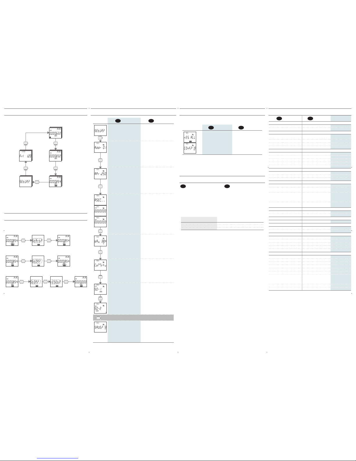
PAGINE PROGRAMMAZIONE
SETUP PAGES
I
- ITALIANO
GB
- ENGLISH
› 3 s
PAGINA PER L’ACCESSO A
PROGRAMMAZIONE
SETUP ACCESS
PAGE
INDIRIZZO MODBUS (01...F7 Hex)
Disponibile solo in caso di modulo
RS485 MODBUS abbinato
Premere il tasto 2 volte veloce, il1.
primo digit inizierà a lampeggiare.
Premere il tasto una volta per2.
cambiare valore.
Confermare premendo il tasto 23.
volte veloce.
Ripetere i punti 2 e 3 per il digit4.
successivo.
MODBUS ADDRESS (01...F7 Hex)
Available only in case of combined
RS485 MODBUS module
Press the key twice quickly, the first
1.
digit will start to flash.
Press the key once to change the
2.
value.
Confirm by pressing the key twice
3.
quickly.
Repeat points 2 and 3 for the next
4.
digit.
INDIRIZZO PRIMARIO M-BUS (0...250)
Disponibile solo in caso di modulo
M-BUS abbinato
Premere il tasto 2 volte veloce, il1.
primo digit inizierà a lampeggiare.
Premere il tasto una volta per2.
cambiare valore.
Confermare premendo il tasto 23.
volte veloce.
Ripetere i punti 2 e 3 per gli altri4.
digit.
M-BUS PRIMARY ADDRESS (0...250)
Available only in case of combined
M-BUS module
Press the key twice quickly, the first
1.
digit will start to flash.
Press the key once to change the
2.
value.
Confirm by pressing the key twice
3.
quickly.
Repeat points 2 and 3 for the other
4.
digits.
INDIRIZZO SECONDARIO M-BUS
(0...99999999)
Disponibile solo in caso di modulo
M-BUS abbinato
Il valore è riportato su due pagine:
pagina 1 (>): digit da 7 a 1•
pagina 2 (<) : digit da 8 a 2•
Premere il tasto 2 volte veloce, il1.
digit 8 dell’indirizzo secondario
inizierà a lampeggiare.
Premere il tasto una volta per2.
cambiare valore.
Confermare premendo il tasto 23.
volte veloce.
Ripetere i punti 2 e 3 per gli altri4.
digit.
M-BUS SECONDARY ADDRESS
(0...99999999)
Available only in case of combined
M-BUS module
The value is displayed on 2 pages:
page 1 (>): digit from 7 to 1
•
page 2 (<) : digit from 8 to 2
•
Press the key twice quickly, the
1.
digit 8 of the secondary address will
start to flash.
Press the key once to change the
2.
value.
Confirm by pressing the key twice
3.
quickly.
Repeat points 2 and 3 for the other
4.
digits.
VELOCITA’ DI COMUNICAZIONE
Pagina e range disponibili a seconda
del modulo di comunicazione
abbinato
Premere il tasto 2 volte veloce, il1.
valore inizierà a lampeggiare.
Premere il tasto una volta per2.
cambiare valore.
Confermare premendo il tasto 23.
volte veloce.
COMMUNICATION SPEED
Page and range available according to
the combined communication module
Press the key twice quickly, the
1.
value will start to flash.
Press the key once to change the
2.
value.
Confirm by pressing the key twice
3.
quickly.
MODALITA’ MODBUS
(RTU=8N1, ASCII=7E2)
Disponibile solo in caso di modulo
RS485 MODBUS abbinato
Premere il tasto 2 volte veloce, la1.
modalità inizierà a lampeggiare.
Premere il tasto una volta per2.
cambiare modalità.
Confermare premendo il tasto 23.
volte veloce.
MODBUS MODE
(RTU=8N1, ASCII=7E2)
Available only in case of combined
RS485 MODBUS module
Press the key twice quickly, the
1.
mode will start to flash.
Press the key once to change the
2.
mode.
Confirm by pressing the key twice
3.
quickly.
CONTATORE ABBINATO ALL’USCITA
S0 (1-2)
Premere il tasto 2 volte veloce,1.
gli elementi che identificano il
contatore (es. >, kWh) inizieranno
a lampeggiare.
Premere il tasto una volta per2.
cambiare contatore da abbinare
all’uscita.
Confermare premendo il tasto 23.
volte veloce.
COUNTER ASSIGNED TO S0 OUTPUT
(1-2)
Press the key twice quickly, the
1.
items which identify the counter
(e.g. >, kWh) will start to flash.
Press the key once to change
2.
the counter to be assigned to the
output.
Confirm by pressing the key twice
3.
quickly.
› 3 s SU QUALSIASI PAGINA DI
PROGRAMMAZIONE
ON ANY
SETUP PAGE
USCITA DA PROGRAMMAZIONE
Premere il tasto una volta per1.
cambiare il valore lampeggiante, Y
per uscire e salvare le impostazioni,
Nper uscire senza salvare, Cper
continuare a scorrere le pagine di
programmazione.
Confermare premendo il tasto per2.
almeno 3 s.
EXIT FROM SETUP
Press the key once to change the
1.
flashing value, Yto exit and save
the settings, Nto exit without
saving, Cto continue scrolling
setup pages.
Confirm by pressing the key at
2.
least 3 s.
AZZERARE I CONTATORI
RESET THE COUNTERS
La pagina RESET si trova all’interno di Programmazione, dopo la pagina di uscita S0-2.
RESET page is displayed in SETUP loop, after S0-2 page.
I
- ITALIANO
GB
- ENGLISH
RESET DEI CONTATORI PARZIALI
Premere il tasto 2 volte veloce,1.
verrà visualizzata una nuova
pagina di conferma.
Premere il tasto una volta per2.
cambiare il valore lampeggiante,
Yper confermare il reset, Nper
annullare.
Confermare premendo il tasto3.
per almeno 3 s.
PARTIAL COUNTERS RESET
Press the key twice quickly, a
1.
new page for confirmation will be
displayed.
Press the key once to change the
2.
flashing value, Yto confirm the
reset, Nto cancel.
Confirm by pressing the key at
3.
least 3 s.
PAGINE INFO
INFO PAGES
I
- ITALIANO
Possono essere visualizzate fino a 5 pagine INFO
contenenti le seguenti informazioni:
Rel. firmware metrologico (rel1)1.
Rel. firmware interfaccia utente (rel2)2.
Checksum parte metrologica (CS1)3.
Checksum interfaccia utente (CS2)4.
Modulo di comunicazione abbinato in uso5.
La quinta pagina, che mostra il tipo di modulo di
comunicazione in uso, cambia a seconda del modulo
abbinatoalcontatore(veditabella).Questapaginanonviene
mostrata se il contatore non ha nessun modulo abbinato.
GB
- ENGLISH
Up to 5 INFO pages can be displayed to show
details about:
Metrological firmware release (rel1)
1.
User interface firmware release (rel2)
2.
Metrological part checksum (CS1)
3.
User interface checksum (CS2)
4.
Combined communication module in use
5.
The fifth page, which shows communication module
inuse, can change accordingto the module combined
with the counter (see table). If the counter has no
combined module this page will not be displayed.
MODULO DI COMUNICAZIONE ABBINATO
COMBINED COMMUNICATION MODULE
INFORMAZIONE VISUALIZZATA SULLA PAGINA INFO
DETAIL DISPLAYED ON THE INFO PAGE
RS485 MODBUS Modbus
M-BUS Mbus
LAN GATEWAY Lan
ACHTUNG!
Geräte-Installation, Verdrahtung und Klemmenabdeckung Dicht dürfen nur durch qualifiziertes Fachpersonal durchgeführt
werden. Vor jeder Tätigkeit am Gerät muß die Versorgung getrennt werden.
WARNING!
Device installation, wiring configuration and terminal cover sealing must be carried out only by qualified professional staff.
Switch off the voltage before device installation.
ABMESSUNGEN (mm)
SIZE (mm)
VERFÜGBARE AUSFÜHRUNGEN
AVAILABLE MODELS
Name
Name
Modell/Port
Model/Port
VerfügbareAnschluß (z.B. 1.2.1=1Phasen,2Leiter,1Strom)
Available wiring (
e.g. 1.2.1=1phase,2wires,1curr.)
Tarifeing.
Tariff input
S0 Ausg.
S0 outputs
MID Eich.
MID cert.
S502-80 IR 1.2.1 1 2
S502-80-MID IR 1.2.1 1 2 •
In allen Modellen dürfen die Teilzähler rückgesetzt werden.
In all device models partial counters are resettable.
ÜBERSICHT
OVERVIEW
D
- DEUTSCH
LCD mit Hintergrundbeleuchtung1.
Multifunktiontaste2.
Messtechnische LED3.
Strom-, Spannung- und4.
Neutralklemmen
Sicherheitsaufkleber (DARF5.
NICHT ENTFERNT WERDEN)
IR Schnittstelle6.
GB
- ENGLISH
Backlight LCD display
1.
Multifunction key
2.
Metrological LED
3.
Current, voltage and neutral
4.
terminals
Safety-sealing
5.
(DO NOT REMOVE)
Porta IR
6.
3
4
6
1
Tariff
5
S0-2 S0-1
2
Die Sicherheitsaufkleber und die plombierbare Klemmenabdeckung sind nur mit MID-Zähler enthalten.
The safety-sealing and the sealable terminal covers are included only with MID certified counters.
SYMBOLE AUF FRONTSEITE (BEISPIELE)
SYMBOLS ON FRONT PANEL (EXAMPLE)
D
- DEUTSCH
GerätenamenA.
HomologationsnummerB.
GenauigkeitsklasseC.
MID Eichung SymbD.
ArbeitstemperaturbereichE.
SeriennummerF.
Data MatrixG.
Integrationskonstante (Messtechnische LED)H.
SchutzartI.
Anschlußbild (Einphasig, 2 Leiter)J.
Nennspannung/FrequenzK.
Grundstromwert (Max Strom)L.
Bei den nicht MID zugelassenen Zählern werden die
Felder B, C und D durch “Cl.1 EN 62053-21” ersetzt.
GB
- ENGLISH
Device name
A.
Type approval certification
B.
Accuracy class
C.
MID approval symbols
D.
Working temperature
E.
Serial number
F.
Data Matrix
G.
Meter constant (metrological LED)
H.
Protection class
I.
Wiring type (1phase, 2 wires)
J.
Nominal voltage/frequency
K.
Base current (max current)
L.
If the device is NO MID version, “Cl.1 EN 62053-21”
will be shown instead of B, C and D fields.
B
C
D
E
F
A
H G
L
K
J
I
TARIFEINGANG
TARIFF INPUT
Das Tarifmanagement wird durch den Anschluß eines externen Gerätes realisiert, dass ein Signal an den
Zähler sendet. Das Signal kann am Tarifeingang folgendes bewirken:
bei einem spannungsfreien Signal (0 V) erhöhen sich die Zählerstände am Tarif 1•
bei einem spannungsführenden Signal (der Wert wird bei den “Technische Daten” angegeben) erhöhen•
sich die Zählerstände am Tarif 2
Bemerkung: Die Gesamtzählerstände erhöhen sich ständig unabhängig vom Status des Tarifeingangs.
The tariff management is carried out by connecting an external device to tariff input, which is providing a
signal to the energy counter. The tariff signal is managed as follows:
if the tariff input detects a voltage free signal (0 V), the device will increase the tariff 1 counters group
•
if the tariff input detects a voltage signal (see Technical features), the device will increase the tariff 2
•
counters group
Note: Total counters increase continuously regardless from the tariff input status.
ANSCHLUSSBILDER
WIRING DIAGRAM
EINPHASIG, 2 LEITER, 1 STROM
SINGLE PHASE, 2 WIRES, 1 CURRENT
L
N
A-V N
<
L
<
A
ANZEIGENSYMBOLE
SYMBOLS ON DISPLAY
D
- DEUTSCH
Bezogener (>), gelieferter (<) Leistungs- oder Energiewert1.
Identifiziert die Einstell- (2. SEtUP) oder Info (InFO) Seiten
Laufende Kommunikation3.
Beschädigten metrologischen Parameter(Code: XX). Der Zähler4.
ist unnutzbar und soll sofort an der Hersteller retouriert werden
Einstellseiten5.
Status des aktiven S0 Ausgangs6.
Messeinheitsfeld7.
Kapazitiv- /Induktivwert8.
Teilzählerwerte. Wenn blinkend ist der Zähler gestoppt9.
Symmetrischer Zählerwert.10.
Symbol+Linie ( )=NEGATIVEN Wert
Zählerwert des Tarifs 1 oder 211.
Hauptanzeigefeld12.
GB
- ENGLISH
Imported (>), exported (<) energy or power value
1.
Identify the Setup page (
2.
SEtUP) or the Info page (InFO)
Communication active status
3.
Metrological parameters corrupted (Code: XX). Useless
4.
counter, to return to the Manufacturer
Setup page
5.
S0-1 / S0-2 output active status
6.
Measuring unit area
7.
Capacitive or inductive value
8.
Partial counter value. Flashing=stopped counter
9.
Balance counter value.
10.
Symbol+line ( )=NEGATIVE value
1 or 2 tariff counter value
11.
Main area
12.
1 3 4 62
911 10 7812
5
MESSUNGEN
MEASUREMENTS
SYMBOL
SYMBOL
MESSEINHEIT
MEASURE UNIT
ANZEIGE
DISPLAY
PORT
PORT
ECHTZEITWERTE
INSTANTANEOUS VALUES
Spannung
Voltage
V V 
Strom
Current
I A 
Leistungsfaktor
Power factor
PF 
Scheinleistung
Apparent power
S kVA  
Wirkleistung
Active power
P kW  
Blindleistung
Reactive power
Q kvar  
Frequenz
Frequency
f Hz 
Leistungrichtung
Power direction
>
< 
GESPEICHERTE WERTE
RECORDED DATA
Gesamtwirkenergie
Total active energy
L kWh  
Gesamtblindenergie ind. und kap.
Total ind. and cap. reactive energy
L kvarh  
Gesamtscheinenergie ind. und kap.
Total ind. and cap. apparent energy
L kVAh  
Energiezähler Tarif T1/T2
T1/T2 tariff energy counters
L kWh, kvarh, kVAh  
Rücksetzbare Energieteilzähler
Resettable partial energy counters L kWh, kvarh, kVAh  
Energiebilanz
Energy balance
L kWh, kvarh, kVAh  
WEITERE ANGABEN
OTHER INFORMATION
SYMBOL
SYMBOL
WERT/STAND
VALUE/STATUS
ANZEIGE
DISPLAY
PORT
PORT
Aktueller Tarif
Present tariff
T 1/2 
Spannung über / unter der Grenze
Undervoltage/overvoltage
VOL, VUL ON/OFF 
Strom über / unter der Grenze
Undercurrent/overcurrent
IOL, IUL ON/OFF 
Frequenz außerhalb des Bereichs
Frequency out of range
fOL, fUL ON/OFF 
Teilzähler
Partial counters
PAR START/STOP  
S0-1 / S0-2 Ausgang Status
S0-1 / S0-2 output status
, Active/Not active 
Bedeutung: = Standard = Bidirektionalwert
Legend:

= Standard

= Bidirectional value
Alle Systemwerte (kWh, kvarh, kVAh) auf S0-Ausgang zugeordnet werden. Es ist nicht möglich, der selbe
Zähler für beide Ausgänge auszuwählen.
All total counters (kWh, kvarh, kVAh) can be associated to S0 output. It is not allowed to set the same counter
for both outputs.
BILANZZÄHLERWERTE BERECHNUNG
BALANCE COUNTER VALUES CALCULATION
BILANZZÄHLER
BALANCE COUNTER
FORMEL
FORMULA
kWh (>kWh T1) –(<kWh T1) +(>kWh T2) –(<kWh T2)
kVAh ind (>kVAh ind T1) –(<kVAh ind T1) +(>kVAh ind T2) –(<kVAh ind T2)
kVAh cap (>kVAh cap T1) –(<kVAh cap T1) +(>kVAh cap T2) –(<kVAh cap T2)
kvarh ind (>kvarh ind T1) –(<kvarh ind T1) +(>kvarh ind T2) –(<kvarh ind T2)
kvarh cap (>kvarh cap T1) –(<kvarh cap T1) +(>kvarh cap T2) –(<kvarh cap T2)
TASTENFUNKTIONEN
KEY FUNCTIONS
FUNKTION
HOW TO
WO
WHERE
WIE LANGE
PRESS TIME
In der Gruppe blättern
Scroll loops
Jeder Seite außer der Einstellung
Any page except for Setup
Zweimal kurz
Twice quickly
Innerhalb der Seiten einer Gruppe blättern
Scroll pages in a loop
Jede Seite einer Gruppe
Any loops page
Sofort
Instantaneous
Zugang zu den Einstellseiten
Access Setup pages
“Setup?” Seite
“Setup?” page
›3 s
Die Einstellung eines Wertes / Dezimalstelle starten
Enable setup for a value/digit
Einstellseiten
Setup pages
Zweimal kurz
Twice quickly
Wert / Dezimalstelle ändern
Change a value/digit
Einstellseiten
Setup pages
Sofort
Instantaneous
Bestätigung eines Wertes / Dezimalstelle
Confirm a value/digit
Einstellseiten
Setup pages
Zweimal kurz
Twice quickly
Eine Anzahl ändern (Y, N, C)
Change item (Y, N, C)
“Save?” Seite
“Save?” page
Sofort
Instantaneous
Bestätigung einer angezeigten Anzahl (Y, N, C)
Confirm the displayed item (Y, N, C)
“Save?” Seite
“Save?” page
›3 s
Anzeige der dem Zähler zugeordneten Funktionen
Display the functions available for the shown counter
Teilzählerseiten
Partial counters pages
›3 s
Eine Funktion ändern (Start, Stop, Res)
Change function (Start, Stop, Res)
Teilzählerseiten
Partial counters pages
Sofort
Instantaneous
Bestätigung der angezeigten Funktion (Start, Stop, Res)
Confirm the displayed function (Start, Stop, Res)
Teilzählerseiten
Partial counters pages
›3 s
Displaytest
Display test
Jeder Seite außer der Einstellung
Any page except for Setup
›10 s
S502-80
80A Einphasiger Energiezähler -
80A single phase energy counter
Änderungen vorbehalten.
Subject to change without prior notice.
1MSOEC80M006
D
- BEDIENUNGSANLEITUNG
GB
- USER MANUAL
SENECA s.r.l.
Via Austria, 26 - 35127 - PADOVA - ITALY
Tel. +39.049.8705355 - 8705359 - Fax +39.049.8706287
e-mail: [email protected] - www.seneca.it
D
- DEUTSCH
GB
- ENGLISH
ALLGEMEIN
GENERAL
Gehäuse gemäß Richtlinie
Housing in compliance with standard
DIN 43880
Klemmen gemäß Richtlinie
Terminals in compliance with standard
EN 60999
HILFSSPANNUNG
POWER SUPPLY
Hilfsspannung wird vom Messkreis
aufgenommen
Power supplied from the voltage
circuit
-
Hilfsspannungsbereich
Voltage range
230...240 V ±20%
Max Verbrauch
Maximum consumption
7,5 VA - 0,5 W
Nennfrequenz
Nominal frequency
50/60 Hz
STROM
CURRENT
Maximalstrom Imax
Maximum current Imax
80 A
Bezugstrom Iref (Ib)
Reference current Iref (Ib
)
5 A
Übergangsstrom Itr
Transitional current Itr
500 mA
Minimalstrom Imin
Minimum current Imin
250 mA
Einschaltungsstrom Ist
Starting current Ist
20 mA
GENAUIGKEIT
ACCURACY
Wirkenergie Klasse B gemäß
Active en. class B in compliance with
EN 50470-3 (MID)
Wirkenergie Klasse 1 gemäß
Active en. class 1 in compliance with
EN 62053-21 (NO MID)
Blindenergie Klasse 2 gemäß
Reactive en. class 2 in compliance with
EN 62053-23
2 S0 AUSGÄNGE
2 S0 OUTPUTS
Passivoptoisolierte
Passive optoisolated
-
Max Werte (gemäß der Richtlinie
EN 62053-31)
Maximum values (in compliance
with EN 62053-31)
250 VAC-DC - 100 mA
Zählerkonstante. Die Messeinheit (imp/
kWh, imp/kvarh, imp/kVAh) ändert sich
entsprechend der zugeordneten Zähler
(kWh∑, kvarh∑, kVAh∑).
Meter constant. The measuring
unit changes according to the
assigned counter (kWh∑, kvarh∑,
kVAh∑).
500
imp/kWh, kvarh, kVAh
Impulsdauer
Pulse length
50 ±2ms ON time
min. 30 ±2ms OFF time
TARIFEINGANG
TARIFF INPUT
Aktivoptoisolierte
Active optoisolated
-
Hilfsspannungsbereich für Tarif 2 (T2)
Voltage range for Tariff 2 (T2)
80...276 VAC-DC
MESSTECHNISCHE PRÜF-LED
METROLOGICAL LED
Zählerkonstante
Meter constant
1000 imp/kWh
ANSCHLIESSBARER LEITER
WIRE DIAMETER FOR TERMINALS
Messeingänge (A & V)
Measuring terminals (A & V)
1,5...35 mm2
S0 / Tarifausgänge
S0 outputs / tariff terminals
0,14...2,5 mm2
SICHERHEIT GEMÄß EN 50470-1
SAFETY ACCORDING TO EN 50470-1
Verschmutzungsgrad
Pollution degree
2
Schutzklasse (EN 50470-1)
Protective class (EN 50470-1)
II
Impulsspannungsprüfung
Pulse voltage test
1,2/50μs 6kV
AC Spannungsprüfung (EN 50470-3, 7.2)
AC voltage test (EN 50470-3, 7.2)
4 kV
Gehäuse Flammbeständigkeit
Housing material flame resistance
UL 94 class V0
UMGEBUNGSBEDINGUNGEN
ENVIRONMENTAL CONDITIONS
Mechanische Umgebungsbedingungen
Mechanical environmental
M1
Elektromagnetische Umgebungsbedingungen
Electromagnetic environmental
E2
Betriebstemperaturbereich
Operating temperature
-25°C...+55°C
Lagertemperaturbereich
Storage temperature
-25°C...+75°C
Relative Luftfeuchte (ohne Kondensation)
Humidity (without condensation)
max 80%
Sinusförmiger Vibrationsumfang
Sinusoidal vibration amplitude
50 Hz ±0,075 mm
Schutzgrad – Frontseite (gewährleistet
nur bei Installation in einem
Schaltschrank mit mindestens
Schutzart IP51)
Protection degree - frontal part
(granted only in case of
installation in a cabinet with at
least IP51 protection degree)
IP51
Klemmenschutzart
Protection degree - terminals
IP20
INTERNE ANWENDUNG
INTERNAL USE
-
TECHNISCHE EIGENSCHAFTEN
TECHNICAL FEATURES
ANZEIGE REIHENFOLGE
PAGE STRUCTURE
Die Seiten des Gerätes sind in 5 Gruppen unterteilt. Die Taste einmal drücken, um in den Seiten einer
Gruppe zu blättern.
Device pages are grouped in 5 loops. Press the key once to scroll pages in a loop.

GESAMTZÄHLER WERTE
TOTAL COUNTERS

TEIL - BILANZZÄHLERWERTE UND
ECHTZEITWERTE
PARTIAL, BALANCE COUNTERS
AND REALTIME VALUES

EINSTELLUNGEN
SETUP

GERÄTEANGABEN
DEVICE INFO

WERTE DER TARIFZÄHLER 1-2
TARIFF 1-2 COUNTERS
Zweimal kurz
Twice quickly
Zweimal kurz
Twice quickly
Zweimal kurz
Twice quickly
Zweimal kurz
Twice quickly
Zweimal kurz
Twice quickly
TEILZÄHLER STARTEN/SPERREN/RÜCKSETZEN
HOW TO START / STOP / RESET PARTIAL COUNTERS
Die Funktion ist nur bei der Teilzählerseite verfügbar.
Feature available only on partial counter pages.
DIE ANGEZEIGTEN TEILZÄHLER STARTEN
HOW TO START DISPLAYED PARTIAL COUNTER
› 3 s › 3 s
STOPPEN ZUVOR GESTARTETER TEILZÄHLER
HOW TO STOP DISPLAYED PARTIAL COUNTER PREVIOUSLY STARTED
› 3 s › 3 s
ANGEZEIGTE TEILZÄHLER ZURÜCKSETZEN
HOW TO RESET DISPLAYED PARTIAL COUNTER
› 3 s › 3 s
EINSTELLSEITEN
SETUP PAGES
D
- DEUTSCH
GB
- ENGLISH
› 3 s
ZUGANGSSEITE ZUM
MENÜ EINSTELLUNGEN
SETUP ACCESS
PAGE
MODBUS ADRESSE (01...F7 Hex)
Verfügbar nur mit dem entsprechenden
RS485 Kommunikationsmodul
Drücken Sie die Taste zweimal1.
kurz, die erste Stelle blinkt.
Zur Wertänderung drücken Sie die2.
Taste einmal.
Zur Bestätigung drücken Sie die3.
Taste zweimal kurz.
Die Punkte 2 und 3 zur Einstellung4.
der darauffolgenden Stelle
wiederholen.
MODBUS ADDRESS (01...F7 Hex)
Available only in case of combined
RS485 MODBUS module
Press the key twice quickly, the first
1.
digit will start to flash.
Press the key once to change the
2.
value.
Confirm by pressing the key twice
3.
quickly.
Repeat points 2 and 3 for the next
4.
digit.
M-BUS PRIMÄRADRESSE (0...250)
Verfügbar nur mit dem entsprechenden
M-BUS Kommunikationsmodul
Drücken Sie die Taste zweimal1.
kurz, die erste Stelle blinkt.
Zur Wertänderung drücken Sie die2.
Taste einmal.
Zur Bestätigung drücken Sie die3.
Taste zweimal kurz.
Die Punkte 2 und 3 zur Einstellung4.
der darauffolgenden Stelle
wiederholen.
M-BUS PRIMARY ADDRESS (0...250)
Available only in case of combined
M-BUS module
Press the key twice quickly, the first
1.
digit will start to flash.
Press the key once to change the
2.
value.
Confirm by pressing the key twice
3.
quickly.
Repeat points 2 and 3 for the other
4.
digits.
M-BUS SEKUNDÄRADRESSE (0...99999999)
Verfügbar nur mit dem entsprechenden
M-BUS Kommunikationsmodul
Der Wert wird auf zwei Seiten angezeigt:
Seite 1 (>): von Stelle 7 zu 1•
Seite 2 (<): von Stelle 8 zu 2•
Zweimal kurz die Taste1.
drücken, damit die Stelle 8 der
Sekundäradresse blinkt.
Zur Wertänderung drücken Sie die2.
Taste einmal.
Zur Bestätigung drücken Sie die3.
Taste zweimal kurz.
Die Punkte 2 und 3 zur Einstellung4.
der darauffolgenden Stelle
wiederholen.
M-BUS SECONDARY ADDRESS
(0...99999999)
Available only in case of combined
M-BUS module
The value is displayed on 2 pages:
page 1 (>): digit from 7 to 1
•
page 2 (<): digit from 8 to 2
•
Press the key twice quickly, the
1.
digit 8 of the secondary address will
start to flash.
Press the key once to change the
2.
value.
Confirm by pressing the key twice
3.
quickly.
Repeat points 2 and 3 for the other
4.
digits.
KOMMUNIKATIONSGESCHWINDIGKEIT
DieSeiteund entsprechend Wertebereiche
hängenvondemangeschlossenen
Kommunikationsmodul ab
Drücken Sie die Taste zweimal1.
kurz, die erste Stelle blinkt.
Zur Wertänderung drücken Sie die2.
Taste einmal.
Zur Bestätigung drücken Sie die3.
Taste zweimal kurz.
COMMUNICATION SPEED
Page and range available according to
the combined communication module
Press the key twice quickly, the
1.
value will start to flash.
Press the key once to change the
2.
value.
Confirm by pressing the key twice
3.
quickly.
MODBUS MODUS
(RTU=8N1, ASCII=7E2)
Verfügbar nur mit dem entsprechenden
RS485 Kommunikationsmodul
Drücken Sie die Taste zweimal1.
kurz, die erste Stelle blinkt.
Zur Modusänderung drücken Sie2.
die Taste einmal.
Zur Bestätigung drücken Sie die3.
Taste zweimal kurz.
MODBUS MODE
(RTU=8N1, ASCII=7E2)
Available only in case of combined
RS485 MODBUS module
Press the key twice quickly, the
1.
mode will start to flash.
Press the key once to change the
2.
mode.
Confirm by pressing the key twice
3.
quickly.
S0 ZUGEWIESENER ZÄHLERSTÄND
(1-2)
Zur Zähleridenfizierung (z.B. >,1.
kWh) drücken Sie die Taste zweimal
kurz.
Zur Änderung der zugewiesene2.
Zählerstand drücken Sie die Taste
einmal.
Zur Bestätigung drücken Sie die3.
Taste zweimal kurz.
COUNTER ASSIGNED TO S0 OUTPUT
(1-2)
Press the key twice quickly, the
1.
items which identify the counter
(e.g. >, kWh) will start to flash.
Press the key once to change
2.
the counter to be assigned to the
output.
Confirm by pressing the key twice
3.
quickly.
› 3 s IN ALLEN
EINSTELLSEITE
ON ANY
SETUP PAGE
AUSGANG AUS EINSTELLANZEIGEN
Drücken Sie die Taste einmal zur1.
Änderung des blinkenden Wertes.
Drücken Sie Yzum Verlassen mit
Speicherung der Änderungen, N
zum Verlassen ohne Speicherung
und Czum weiteren Blättern
zwischen den Einstellseiten.
Zur Bestätigung die Taste länger2.
als 3 Sekunden drücken.
EXIT FROM SETUP
Press the key once to change the
1.
flashing value, Yto exit and save
the settings, Nto exit without
saving, Cto continue scrolling
setup pages.
Confirm by pressing the key at
2.
least 3 s.
ZÄHLER RÜCKSTELLEN
RESET THE COUNTERS
Die Seite Rücksetzen befindet sich in der Einstellungen nach der S0-2 Ausgangsseite.
RESET page is displayed in SETUP loop, after S0-2 page.
D
- DEUTSCH
GB
- ENGLISH
TEILZÄHLER ZU RÜCKSETZEN
Durch Drücken zweimal schnell1.
1. der Taste wird eine Bestätigung
angefordert.
Einmal die Taste zur Änderung2.
des blinkenden Wertes drücken: Y
zur Bestätigung des rücksetzens
und Nzum beenden.
Mehr als 3 s die Taste zur3.
Bestätigung drücken.
PARTIAL COUNTERS RESET
Press the key twice quickly, a
1.
new page for confirmation will be
displayed.
Press the key once to change the
2.
flashing value, Yto confirm the
reset, Nto cancel.
Confirm by pressing the key at
3.
least 3 s.
INFO SEITEN
INFO PAGES
D
- DEUTSCH
Bis zu 5 Seiten können vorhanden sein:
Messtechnische Firmwarestand (rel1)1.
Benutzeroberfläche Firmwarestand (rel2)2.
Messtechnische Prüfsumme (CS1)3.
Benutzeroberfläche Prüfsumme (CS2)4.
Vorhandenes Kommunikationsmodul in Betrieb5.
Die fünfte Seite, die das im Betrieb
Kommunikationsmodul anzeigt, hängt von dem
vorhandenen Modul ab (siehe Tabelle). Diese Seite
fehlt wenn kein Modul vorhanden ist.
GB
- ENGLISH
Up to 5 pages can be displayed to show details about:
Metrological firmware release (rel1)
1.
User interface firmware release (rel2)
2.
Metrological part checksum (CS1)
3.
User interface checksum (CS2)
4.
Combined communication module in use
5.
The fifth page, which shows communication module
inuse, can change accordingtothe module combined
with the counter (see table). If the counter has no
combined module this page will not be displayed.
VORHANDEN KOMMUNIKATIONSMODUL
COMBINED COMMUNICATION MODULE
ANGABEN AUF DIE INFO SEITE
DETAIL DISPLAYED ON THE INFO PAGE
RS485 MODBUS Modbus
M-BUS Mbus
LAN GATEWAY Lan

Popular Cash Counter manuals by other brands

TSI Instruments AEROTRAK 7201-A2F Operation manual

TSI Instruments

TSI Instruments AEROTRAK 7201-A2F Operation manual

Falcon F900 SERIES User, installation and servicing instructions

Falcon

Falcon F900 SERIES User, installation and servicing instructions

Royal Sovereign RBC-ED350 owner's manual

Royal Sovereign

Royal Sovereign RBC-ED350 owner's manual

Hengstler tico 731.2 operating instructions

Hengstler

Hengstler tico 731.2 operating instructions

Quick CHC1103 Manual of installation and use

Quick

Quick CHC1103 Manual of installation and use

PCE Instruments PCE-MPC 20 user manual

PCE Instruments

PCE Instruments PCE-MPC 20 user manual

Hengstler Tico 731.1 operating instructions

Hengstler

Hengstler Tico 731.1 operating instructions

Volumatic CountEasy Advanced configuration manual

Volumatic

Volumatic CountEasy Advanced configuration manual

Safescan 1200 user manual

Safescan

Safescan 1200 user manual

Agilent Technologies 53181A operating guide

Agilent Technologies

Agilent Technologies 53181A operating guide

Eaton MN05401014E operating instructions

Eaton

Eaton MN05401014E operating instructions

Pahlen Jet Swim Motion user manual

Pahlen

Pahlen Jet Swim Motion user manual

Cassida 6600 Cleaning procedure

Cassida

Cassida 6600 Cleaning procedure

Pecunia T 90 M Operation manual

Pecunia

Pecunia T 90 M Operation manual

Yatai JC Series user manual

Yatai

Yatai JC Series user manual

Nautilus Hyosung MONiMAX5600 Service manual

Nautilus Hyosung

Nautilus Hyosung MONiMAX5600 Service manual

THORLABS SPCNT user guide

THORLABS

THORLABS SPCNT user guide

SILTRONIX FD-1011 manual

SILTRONIX

SILTRONIX FD-1011 manual

manuals.online logo
manuals.online logoBrands
  • About & Mission
  • Contact us
  • Privacy Policy
  • Terms and Conditions

Copyright 2025 Manuals.Online. All Rights Reserved.