Seneca Z202-LP User manual

EN
GENERALFEATURES
The Z202-LP module is a loop-powered voltage transmitter that measures the alternate
(meanvalueadjustedtothermsvalue)anddirectvoltageinputvalue andconvertsitintoa
current signal output. The instrument stands out for its precision class, low power
consumptionandwiderangeofconfigurationoptions.
Theseareitsgeneralfeatures:
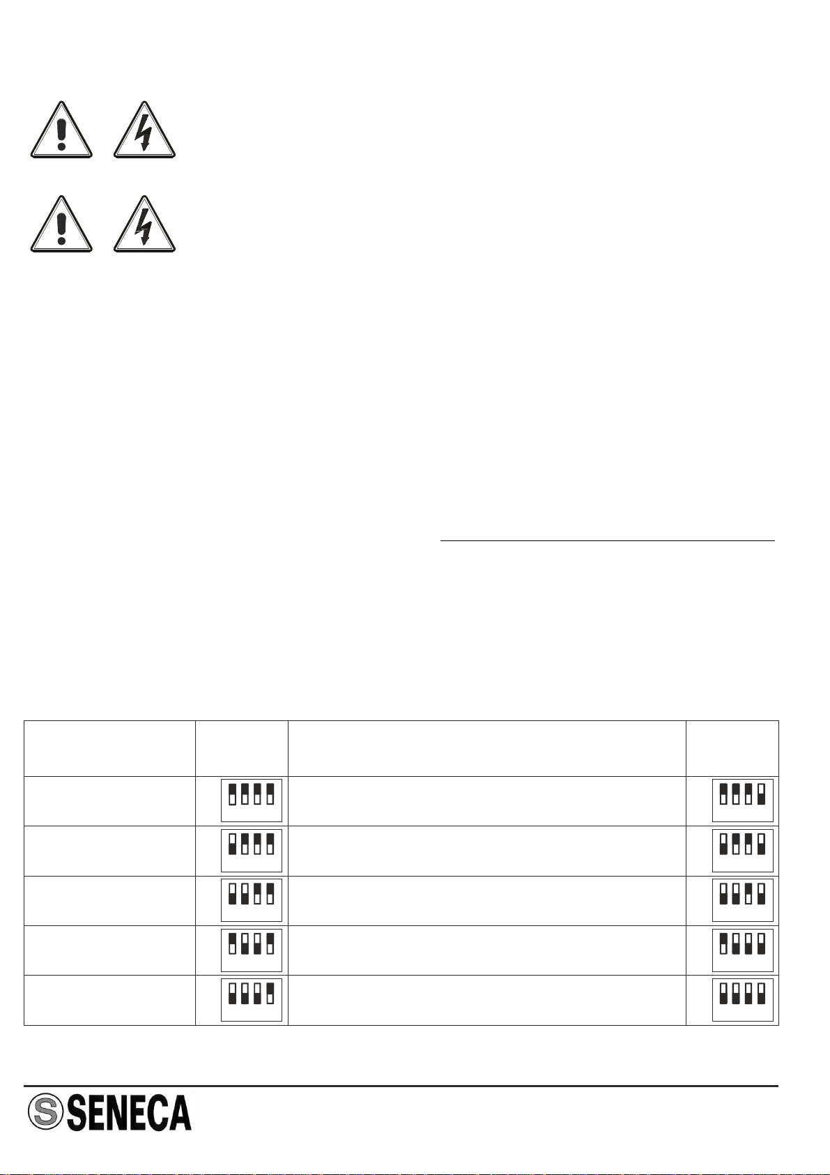
Voltageinputupto500Vacin5presetranges,whichcanbeselectedbyDIP-switch.
Each range can be set and extended to the next one, and it's possible to calibrate the
instrument on any intermediate point in the continuous range of 0..500 Vac, without
either over-setting the fixed ranges, or opening the instrument (multi-rev trimmer
accessiblefromfrontpanel).
Highprecisionclass: 0.3(on300Vacofmaximumrange).
Widerangeoffrequencyinput (20Hz..400Hz).
Extremelyshortresponsetime(<100ms).
3750Vacgalvanicinsulationbetweenvoltageinputand outputports.
Lowoutputrippleandfastresponsetimetoinputchange.
ALTERNATE AND DIRECT VOLTAGE
TRANSMITTER Z202-LP
TECHNICAL SPECIFICATIONS
Input Specifications
Loop Specifications
Voltage input: Alternate voltage 0..500 Vac; direct voltage 0..540 Vdc; see
the range selection table.
Frequency: DC / 20 Hz .. 400 Hz
Insulation: 3750Vac
Overvoltage
measurement Class: CAT III up to 300 Vac towards ground.
CAT II up to 300 Vac towards ground.
General Specifications: Passive, 4..20 mA
Maximum current: 35 mA in overload conditions.
Extern power supply
voltage: From 5 to 28 Vdc.
Response time: For a stepped variation: < 100 ms from 10 to 90 %.
Maximum Voltage: 710Vpkrangeindependent.
ENGLISH - 1/6MI00138 -E3
Consumption: < 1mA for any input voltage.

MI00138 -E3 ENGLISH - 2/6
(1): Maximum error must be increased by 20 µA for input voltages lower than 10 Vac or for direct
voltages.
(2):Themeasurementerrorsareindicatedforasinusoidalsignal.
(3): Acronyms“o.m.”standsfor “ofmeasurement”.
Accuracy specifications (1)(2)
Other Specifications
Range Measurement error(3)
100 Vac / 90 Vdc 0,3 % o.m. + 70 µA
200 Vac / 180 Vdc 0,3 % o.m. + 40 µA
300 Vac / 270 Vdc 0,2 % o.m. + 30 µA
400 Vac / 360 Vdc 0,3 % o.m. + 30 µA
500 Vac / 450 Vdc 0,3 % o.m. + 30 µA
Thermal drift 150ppm / K
EMI Error < 40 µA
Operating conditions: Temperature: -20..65°C, humidy 30..90 % @ 40°C not-
condensing. Climatic Group III.
Storage Temperature : -20..85 °C.
Altitude: up to 2000 m a.s.l.
International protection: IP20
Weight, dimensions: 140 g, 100 x 112 x 17.5 mm.
Standards: EN60688 (rated input voltage = 300 Vac)
EN61000-6-4 (electromagnetic emission, industrial
environment).
EN61000-6-2 (electromagnetic immunity, industrial
environment).
EN61010-1 ( ).safety

MI00138 -E3 ENGLISH - 3/6
INSTALLATIONRULES
The module is designed to be installed on a DIN 46277 guide, and wired only by front
terminals.
We suggest you to install the instrument vertically in order to arrange the ventilation of the
module and pay attention to do not fitany objects or canals that can obstruct its ventilation
louvers.Avoid fitting modules above equipment that generates heat; you are advised to fit
thematthebottomofthepanelorontheenclosingcompartment.
Overall Dimensions / DIP-switch Position
SWITCH
17,5 mm
100 mm
ON
KEY

MI00138 -E3 ENGLISH - 4/6
ATTENTION!
BEFORE YOU ATTEMPT USING THE DIP-SWITCH, MAKE SURE
THAT YOU HAVE DISCONNECTED ALL CIRCUITS AT
DANGEROUSVOLTAGE.
The instrument satisfies standard 60688/1997; in particular, overvoltage tests of input
voltagearereferredto giveinOtherSpecifications.ratedinputvoltage
Voltage overloads higher than maximum voltage given in Input Specifications may
damagetheinstrument.
The range of the instrument is established by the positions of the 4-way DIP-switch. The
firstthreewaysselectoneofthe5 presetranges,whilethefourthway(usuallyoff)enables
the insertion of the trimmer on panel, which gives a continuous-control extended range of
0..100 Vac (0..90 Vdc): if you rotate the trimmer clockwise you increase the output
(reducing the maximum range of the instrument), else you reduce the output increasing
the maximum range. If input voltage is present, ,you must use an insulated screwdriver
becausetheinsulationoftheadjustingscrewisnotguaranteed.
Lower voltage input is 4 Vac o 5 Vdc for any range. These values are the amplitude
thresholdsunderwhichtheinstrumentdetects0,thatistransmits4mA.
Thetablebelowshowsthecombinationsusefulforthepresetrangevalues.
INPUT FULL SCALE SETTINGS
Range Range / TrimmerDIP
100Vac / 90 Vdc 100 Vac + 0..100 Vac / 90 Vdc + 0..90 Vdc
200Vac / 180 Vdc 200 Vac + 0..100 Vac / 180 Vdc + 0..90 Vdc
300Vac / 270 Vdc 300 Vac + 0..100 Vac / 270 Vdc + 0..90 Vdc
400Vac / 360 Vdc 400 Vac + 0..100 Vac / 360 Vdc + 0..90 Vdc
500Vac / 450 Vdc 500 Vac + 0..100 Vac / 450 Vdc + 0..90 Vdc(1)
DIP
12 34
12 34
12 34
12 34
12 34
12 34
12 34
12 34
12 34
12 34
12 34
on
off
on
off
on
off
on
off
on
off
on
off
on
off
on
off
on
off
on
off
(1): Maximum input voltage must not exceed 500 Vac o 710 Vpk anyway.
ATTENTION!
TO ADJUST THE TRIMMER ON PANEL AN INSULATED
SCREWDRIVERMUSTBEUSED.

ELECTRICAL CONNECTIONS
ATTENTION!
BEFOREMAKINGANYCONNECTIONTOTHEINSTRUMENT,MAKESURE
THAT YOU HAVE DISCONNECTED ALL CIRCUITS AT DANGEROUS
VOLTAGE.
Loop connections
RANGE: See “INPUT FULL SCALE SETTINGS”
V12
10
3
1
mA Vext
ext. supply
max 28 V
Voltage input connections
MI00138 -E3 ENGLISH - 5/6
1 3
10 12
Z202-LP
ADJ
2
FRONT PANEL
TRIMMER

MI00138 -E3 ENGLISH - 6/6
Thisdocumentisproperty ofSENECAsrl.Duplicationandreprodutionareforbidden,ifnotauthorized.Contentsofthe
presentdocumentationreferstoproductsandtechnologiesdescribedinit.Alltechnicaldatacontainedinthedocument
maybemodifiedwithoutpriornoticeContentofthisdocumentationissubjecttoperiodicalrevision.
SENECA s.r.l.
Via Austria, 26 - 35127 - PADOVA - ITALY
Tel. +39.049.8705355 - 8705359 - Fax +39.049.8706287
e-mail: info@seneca.it - www.seneca.it
THE INTERNATIONAL CERTIFICATION NETWORK
R
ISO9001-2000
Disposal of Electrical & Electronic Equipment (Applicable throughout the
European Union and other European countries with separate collection
programs)
This symbol, found on your product or on its packaging, indicates that this product
should not be treated as household waste when you wish to dispose of it. Instead, it
should be handed over to an applicable collection point for the recycling of electrical
and electronic equipment. By ensuring this product is disposed of correctly, you will
help prevent potential negative consequences to the environment and human health,
which could otherwise be caused by inappropriate disposal of this product. The
recycling of materials will help to conserve natural resources. For more detailed
information about the recycling of this product, please contact your local city office,
wastedisposalserviceorthèretailstorewhereyoupurchasedthisproduct.


Table of contents
Other Seneca Transmitter manuals