Sennheiser FO-TX 2-EC User manual
FO-TX 2-EC
FO-TX 2-OPT
FO-RX 2-EC
Instruction manual
FO-TX 2-EC
FO-TX 2-OPT
FO-RX 2-EC
Revision date: 07/2013
Sennheiser electronic GmbH & Co. KG
Am Labor 1, 30900 Wedemark, Germany
www.sennheiser.com 1/10
Short description
These devices are designed to extend radio microphone remote receiving aerials to distances of up
to 25 km from their associated receivers, allowing receiving antennas to be placed at much greater
distances from the receivers than would be possible using any type of coaxial cable. This is of
particular benefit to outside broadcast units providing coverage of events spread over large sites
for example such as golf courses, horse racing and motor racing circuits.
FO-TX 2-EC (with two E2000-APC fibre out sockets) and
FO-TX 2-OPT (with Neutrik opticalCON DUO™ socket)
The fibre optical transmitters are designed to convert the UHF radio signals from two receiving
antenna feeds and transmit the resulting signals down two cores of single mode optical fibre. The
transmitter can be powered by 240 VAC, 12 VDC or via V-lock battery inside the housing. An internal
switchable bias-T will provide 12 V/200 mA to the antenna inputs for powering head amplifiers
such as the AB 1036 antenna booster. A 3/8” Whitworth thread adaptor is provided to allow for
flexible mounting solutions.
FO-RX 2-EC
The fibre optical receiver converts the resulting signal from the fibre optical transmitter to two RF
outputs. There is visual indication on the unit to display the power status and battery level of the
fibre optical transmitter, as well as indication of the light level received from the individual fibre
cores. The receiver is designed to be coupled alongside a Sennheiser ASA-1 active antenna splitter
active RF distribution unit for additional distribution of RF signals.

FO-TX 2-EC, FO-TX 2-OPT, FO-RX 2-EC
07/2013 2/10
Safety instructions
•Read this instruction manual
•Keep this instruction manual. Always include this instruction manual when passing the product on to
third parties.
•Heed all warnings and follow all instructions in the instruction manual.
•Do not clean the product with abrasives.
•Do not place the product near any heat sources such as radiators, stoves or other devices (including
amplifiers) that produce heat.
•Only use attachments/accessories specified by Sennheiser.
•Refer all servicing to qualified service personnel. Servicing is required if the product has been damaged
in any way, objects have fallen inside, or the product does not operate properly.
•To reduce the risk of short circuits, do not use the FO-RX 2-EC near water and do not expose it to rain or
moisture.
•The FO-TX 2-EC and FO-TX 2-OPT are weather-proof, but should not be exposed to extreme conditions,
and should not be left standing in water.
•Rechargeable cells should be disposed of in a dedicated battery recycling facility.
Replacement parts
When replacement parts are required, be sure the service technician uses replacement parts specified by
Sennheiser. Unauthorized solutions may result in fire, electric shock, or other hazards.
Intended use
Intended use of the product includes:
•Having read these instructions especially the chapter “Safety instructions“.
•Using the products within the operating conditions.
“Improper use” means using the products other than as described in this instruction manual, or under
operating conditions which differ from those described herein.
Delivery includes
FO-TX 2-EC and FO-TX 2-OPT
•13 amp Neutrik powerCON™
•Instruction manual
Note: The internal V-lock battery is not incluced in the delivery (see also on page 5).
FO-RX 2-EC
•Sennheiser NT1-1 UK power supply unit (13.8 VDC/2A), Article No. 503874
•DC link cable for powering the ASA 1 active antenna splitter
•Instruction manual

Contents
FO-TX 2-EC, FO-TX 2-OPT, FO-RX 2-EC
07/2013 3/10
1 Product overview............................................................................................4
1.1 Elements of the FO-TX 2-OPT/FO-TX 2-EC ....................................................... 4
1.2 Internal elements of the FO-TX 2-EC/FO-TX 2-OPT........................................ 5
1.3 Elements of the FO-RX2-EC................................................................................. 6
1.4 Internal elements of the FO-RX2-EC ................................................................. 7
1.5 Block diagram........................................................................................................ 7
2 Technical data.................................................................................................8
3 Important notes for using the devices........................................................9
3.1 FO-TX 2-EC and FO-TX 2-OPT.............................................................................. 9
3.1.1 Powering by DC using a 4-pin XLR socket .....................................................................9
3.1.2 Powering by V-lock battery..............................................................................................9
3.1.3 RF input powering ..............................................................................................................9
3.1.4 Exchanging the optical outputs.......................................................................................9
3.2 FO-RX2-EC .............................................................................................................. 9
4 Manufacturer declarations......................................................................... 10

FO-TX 2-EC, FO-TX 2-OPT, FO-RX2-EC
07/2013 4/10
1 Product overview
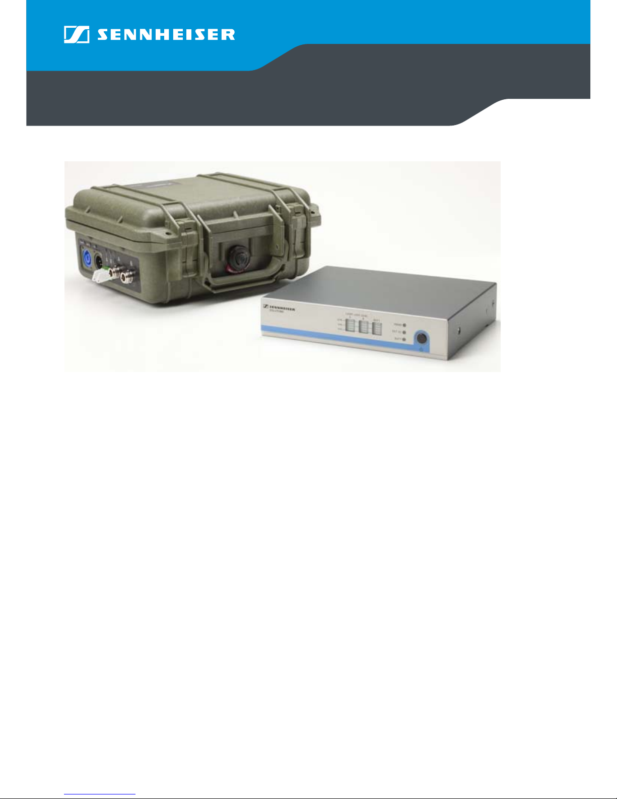
1.1 Elements of the FO-TX 2-OPT/FO-TX 2-EC
쐃Three LED indicators for mains, DC or battery powering mode
쐇Weatherproof 1200 Peli™ case
쐋AC IN mains Neutrik powerCON™socket
쐏12 V DC IN power supply unit socket (XLR-4 male)
쐄FO-TX2-OPT: One Neutrik opticalCON DUO™out socket
FO-TX2-EC: Two E2000-APC fibre out sockets
Note: An opticalCON DUO/E2000-APC adaptor will be available on request.
쐂RF in /12 VDC out socket A
쐆RF in /12 VDC out socket B
FO-TX 2-EC
FO-TX 2-OPT
FO-TX 2-EC, FO-TX 2-OPT, FO-RX2-EC
07/2013 5/10
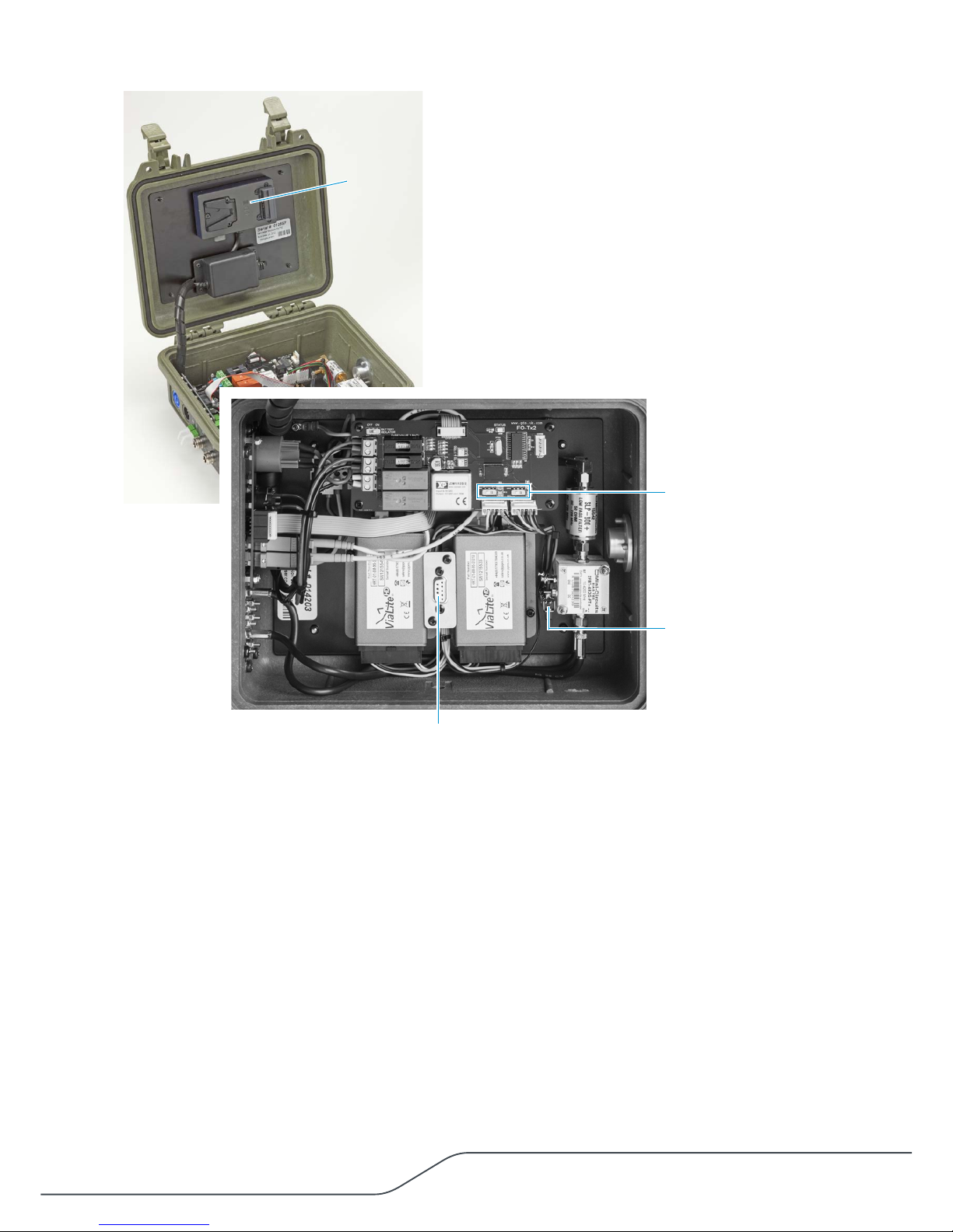
1.2 Internal elements of the FO-TX 2-EC/FO-TX 2-OPT
쐃V-lock battery (not incluced in the delivery)
쐇Two DC switches for the fibre modules
쐋Bias-T switches
쐏Programming port for fibre TX

FO-TX 2-EC, FO-TX 2-OPT, FO-RX2-EC
07/2013 6/10
1.3 Elements of the FO-RX2-EC
쐃Bargraph display for laser light level A
쐇Bargraph display for laser light level B
쐋Bargraph display for the battery level
쐏LED indicators for mains, DC or battery powering mode
쐄ON/OFF button
쐂E2000-APC fibre in socket A
쐆EC2000-APC firbre in socket B
쐊BNC RF out socket A
쐎BNC RF out socket B
쐅Two DC IN sockets for NT 1-1 power supply units (13.8 VDC/2 A max.)
with strain-relief
쐅

FO-TX 2-EC, FO-TX 2-OPT, FO-RX2-EC
07/2013 7/10
1.4 Internal elements of the FO-RX2-EC
쐃DATA SELECT switch for channel A or channel B
The transmitter sends the data (with the battery and power suppy status)
simultaneously to receiver channel A and B . The receiver´s front panel displays
this signal. Select your channel, if you have connect one channel only or if you
would check one connected channel separately.
1.5 Block diagram
FO-RX2-EC FO-TX-2
Optical A
Optical B
RF out A
RF out B
RF receiver
RF in A
RF in B
Antenna A
Antenna B
BNC
BNC
BNC
25 km max.
BNC OPT OPT
RF
transmitting signal

FO-TX 2-EC, FO-TX 2-OPT, FO-RX2-EC
07/2013 8/10
2 Technical data
System
Frequency range 470 MHz to 790 MHz
(other frequency ranges up to 1Ghz will
be available on request)
Distance max. up to 25 km
RF gain 0 dB ±3 dB
FO-TX 2
Power supplies
AC IN (via Neutrik powerCON™plug) 90 to 264 VAC at 50 to 60 Hz
DC IN (via power supply unit) 12 VDC (XLR-4 socket, male)
Pin 1: GND
Pin 4: +12 VDC
Pins 2 and 3 are not connected
Internal V-lock battery (not incluced in the delivery) Commercial V-mount battery
Voltage 14.8 V
Dimensions (L x W x D max) 110 x 73 x 45 mm
Power consumption
with DC power supply unit only, without antennas 600 mA
with AC mains supply only 18 W max.
RF inputs Type N, 50 ohms
Antenna DC supply 12 VDC, max. 200 mA
Fibre connectors
FO-TX 2-EC Two E2000-APC fibre out sockets
FO-TX 2-OPT One Neutrik opticalCON DUO™ socket
Housing type Weatherproof 1200 Peli™ case
Dimensions (L x W x D) approx. 260 x 246 x 124 mm
Weight (without battery) 2.77 kg
FO-RX2-EC
Power supply Sennheiser NT 1-1 power supply unit
with 13.8 VDC/2 A
RF outputs Type N, 50 ohms
Housing type ½ rack width unit
Dimensions (W x D x H) approx. 210 x 190 (with connecors) x 45
Weight (without battery) 2.77 kg
+12 V DC
GND
1
23
4
Not solder side

FO-TX 2-EC, FO-TX 2-OPT, FO-RX2-EC
07/2013 9/10
3 Important notes for using the devices
3.1 FO-TX 2-EC and FO-TX 2-OPT
The transmitters can be powered by 240 VAC, 12 VDC or via V-lock battery inside the
housing. The three powering sources and the transmitter´s battery status will be
transmitted via both fibre channels.
3.1.1 Powering by DC using a 4-pin XLR socket
•The DC power supply unit is not included in the delivery.
•When wiring a 4-pin female XLR to a DC supply, pin 1 to ground and pin 4 to
+12 VDC. The pins 2 and 3 will not be connected (see also on page 8).
3.1.2 Powering by V-lock battery
•The battery is not incluced in the delivery
•The transmitter does not charge the battery, for charging it must be removed.
•The battery can be installed alongside another power source as a backup.
3.1.3 RF input powering
An internal switchable bias-T will provide 12 V/200 mA to the antenna inputs for
powering head amplifiers such as the AB 1036 antenna booster.
3.1.4 Exchanging the optical outputs
For the optical outputs, the unit can be supplied with a Neutrik Opticalcon DUO
socket or two E2000-APC sockets. These can be exchanged in the field by suitable
qualified personnel.
3.2 FO-RX2-EC
•Supply the receiver with the Sennheiser NT 1-1 power supply unit only.
•The two DC jack sockets are wired in parallel and are interchangeable.
•Use the supported DC link cable for powering the ASA 1 active antenna splitter.
•The two laser light level bargraph displays indicate the level of the light signal
received down fibre channels A and B (not the RF level transmitted on that
channel). A low laser level may degrade the output RF signal, however, as there
are many other factors affecting the performance of the connected equipment,
there is no definite threshold level for operation. Rather, these indicators should
be used as fault finding tools.
•The other bargraph display indicates the status of the battery, and the LEDs
indicate the presence of the three possible power sources. In the absence of this
information from a connected FO-TX 2-EC, the LEDs will flash in sequence. As this
information is transmitted down both fibre channels, you may select which
channel is used by the front display, using the internal data select A/B switch.
This will not be necessary in normal operation.
ATTENTION!
Damage of the receiver!
Voltages of more than 16 VDC may irreparably damage the receiver. Ensure that the RF outputs are
not exposed to an excessive bias voltage from the input of the equipment they are connected to.

FO-TX 2-EC, FO-TX 2-OPT, FO-RX2-EC
07/2013 10/10
4 Manufacturer declarations
For the current warranty conditions visit our website at www.sennheiser.com
or contact your Sennheiser partner:
In compliance with
•RoHS Directive (2002/95/EC)
CE Declaration of Conformity
•R&TTE Directive (1999/5/EC)
•EMC Directive (2004/108/EC)
The declarations are available on our website at www.sennheiser.com
Before putting the products into operation, please observe the respective
country-specific regulations.
10
This manual suits for next models
2
Table of contents
Other Sennheiser Extender manuals


Popular Extender manuals by other brands


Noqon
Noqon NB Series Installation and operating instructions

Ihse
Ihse K474 Series user manual

SureCall
SureCall Fusion2Go Max user guide

Digitus
Digitus DS-55202 Quick installation guide

Lindy
Lindy HDMI over Ethernet Extender user manual

Contemporary Control Systems
Contemporary Control Systems TD960801-0MC user manual


