PVI VeCOAX ULTRA-HDMI-QAM-IP User manual

VeCOAX ULTRA-HDMI-QAM-IP
User Manual

Directory
CHAPTER 1 INTRODUCTION...................................................................................................... 1
1.1 PRODUCT OVERVIEW .................................................................................................................1
1.2 KEY FEATURES ..........................................................................................................................1
1.3 SPECIFICATIONS......................................................................................................................... 2
1.4 PRINCIPLE CHART......................................................................................................................4
CHAPTER 2 INSTALLATION GUIDE...........................................................................................6
2.1 GENERAL PRECAUTIONS.............................................................................................................6
2.2 POWER PRECAUTIONS................................................................................................................6
2.3 DEVICE’S INSTALLATION ............................................................................................................6
2.4 ENVIRONMENT REQUIREMENT ....................................................................................................7
2.5 GROUNDING REQUIREMENT........................................................................................................ 7
CHAPTER 3 WEB NMS OPERATION..........................................................................................8
3.1 ENCODER LOGIN ........................................................................................................................8
3.2 ENCODER MODULATOR OPERATION ............................................................................................9
CHAPTER 4 TROUBLESHOOTING........................................................................................... 21
CHAPTER 5 PACKING LIST......................................................................................................22

Copyright 2017 ProVideoInstruments USA –All Rights Are Reserved Page 1 / 24
Chapter 1 Introduction
1.1 Product Overview
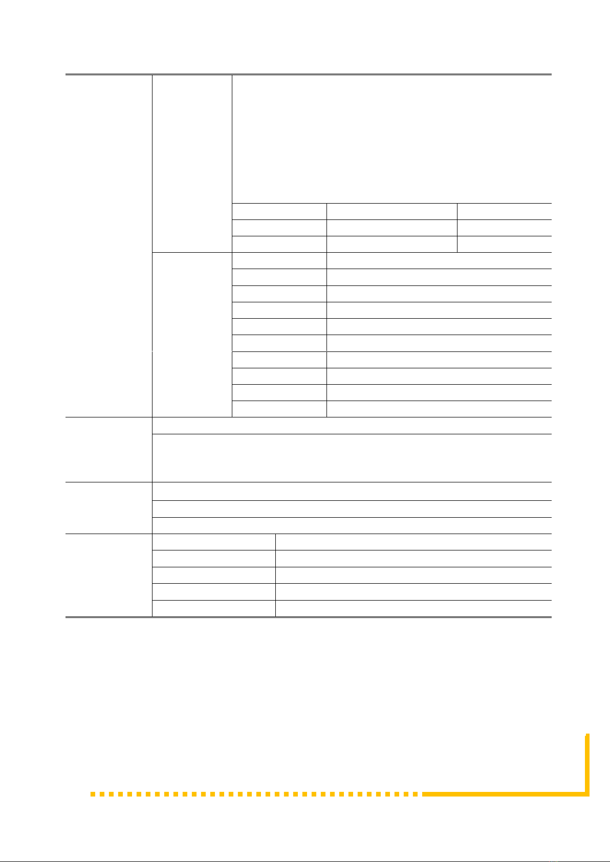
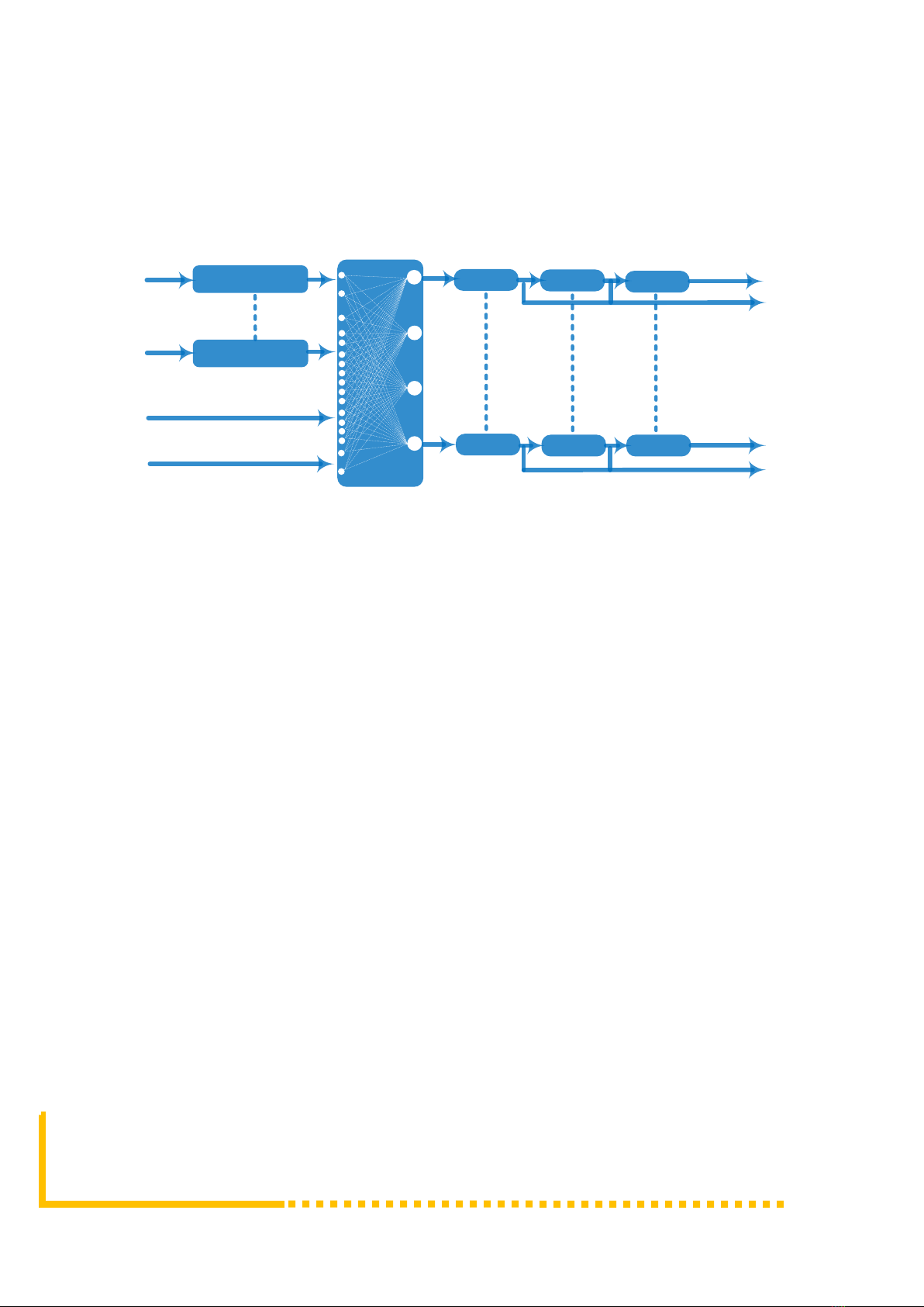
VECOAX ULTRA HD encoder modulator is a professional high integration
device which includes encoding, multiplexing, scrambling and modulation. It
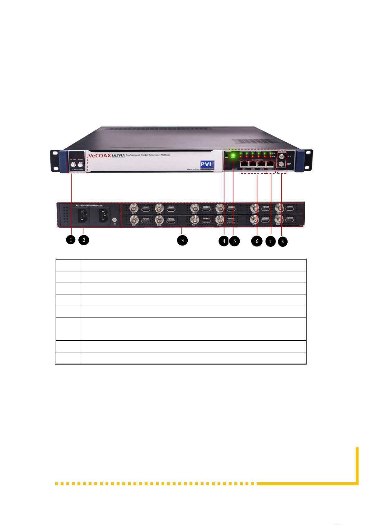
supports up to 12 HDMI and 12 CC inputs, one ATSC tuner input and 256 IP
input through Data1 (GE) port. It also supports QAM RF out with 16
non-adjacent carries and supports 16 MPTS as mirror of 16 carriers through
Data2 (GE) output port. This full function device makes it ideal for CATV head
end system as well any other Professional Quality Video Transmission &
Distribution
1.2 Key Features
•UP TO 12 HDMI inputs with MPEG2 & MPEG4 AVC/H.264 Encoding
•UP TO 12 CC(Closed Caption) input port
•1ATSC tuner input for re-mux
•256 IP(DATA1 port only) input over UDP and RTP protocol
•MPEG1 Layer II, MPEG2-AAC, MPEG4-AAC, Dolby Digital AC3 (2.0)
encoding, AC3 (2.0/5.1) passthrough
•Support 16 groups multiplexing/Scrambling/RF modulating
•Support 16 MPTS IP (DATA2 port only) output over UDP, RTP/RTSP
•Support PID remapping/ accurate PCR adjusting/PSI/SI editing and
inserting
•Control via web management, and easy updates via web
•Modular Expandable

Page 2 / 24 Copyright 2017 ProVideoInstruments USA –All Rights Are Reserved
1.3 Specifications
Input
Up To 12 HDMI inputs
Up To 12 CC(closed caption) input, BNC interface
1 ATSC Tuner for re-mux, F type interface ( other standards upon request )
256 IP input over UDP and RTP, DATA1, RJ45
Video
Resolution
Input
1920*1080_60p, 1920*1080_50p,1920*1080_60i,
1920*1080_50i, 1280*720_60p, 1280*720_50P,
720*480_60i, 720*576_50i
Output
1920*1080_60p, 1920*1080_50p,1920*1080_60i,
1920*1080_50i, 1440*1080_60i, 1440*1080_50i,
1280*720_60p, 1280*720_50P, 720*576_50p,
720*576_50i, 720*576_30p, 720*576_25p,
720*480_60p, 720*480_60i,720*480_30p,
720*480_25p,320*240_60p,320*240_50p,
320*240_30p, 320*240_25p,320*180_60p,
320*180_50p, 320*180_30p, 320*180_25p,
960*540_50i, 704*576_50i,704*480_60i, 640*576_50i
640*480_60i, 544*576_50i,544*480_60i,
Encoding
MPEG2 & MPEG4AVC/H.264
Bit-rate
0.8~19Mbps for H.264 encoding
1~19Mbps for MPEG-2 encoding
Rate Control
CBR/VBR
GOP
Structure
GOP B Frame: 0-3, GOP P Frame: 0-6
Advanced
Pretreatment
De-interlacing, noise reduction
Audio
Encoding
MPEG1 Layer II, MPEG2-AAC, MPEG4-AAC,
Dolby Digital AC3 (2.0) encoding (Optional),
AC3 (2.0/5.1) passthrough
Sampling rate
48KHz
Resolution
24-bit
Bit-rate
64Kbps-320kbps each channel
Multiplexing
Maximum PID
Remapping
256 input per channel
Function
PID remapping ( automatically or manually)
Accurate PCR adjusting
Generate PSI/ SI table automatically
Scrambling
Maximum
simulcrypt CA
4
Standard
EN300 429/ITU-T J.83A/B
Connection
Local/remote connection

Copyright 2017 ProVideoInstruments USA –All Rights Are Reserved Page 3 / 24
Modulation
DVB-C
QAM Channel: 16 non-adjacent carriers output (maximum
bandwidth 192MHz)
Standard: EN300 429/ITU-T J.83A/B
MER: ≥40db
RF frequency: 50~960MHz, 1KHz step
RF output level: -20~+10dbm (87~107 dbµV), 0.1db step
Symbol Rate: 5.0Msps~7.0Msps, 1ksps stepping
Constellation: 16/32/64/128/256QAM
J.83A
J.83B
Constellation
16/32/64/128/256QAM
64/256 QAM
Bandwidth
8M
6M
Stream output
RF output (F type interface)
16 MPTS output over UDP and RTP/RTSP as mirror of 16 DVB-C carriers,
8 MPTS output over UDP and RTP/RTSP as mirror of 8 DVB-T carriers(Optional)
1*1000M Base-T Ethernet interface
System
function
Network management (WEB)
Chinese and English language
Ethernet software upgrade
Miscellaneous
Dimension (W×L×H)
482mm×440mm×44mm
Approx weight
8kg
Environment
0~45℃(work);-20~80℃(Storage)
Power requirements
AC 110V± 10%, 50/60Hz,AC 220 ± 10%, 50/60Hz
Power consumption
20W

Page 4 / 24 Copyright 2017 ProVideoInstruments USA –All Rights Are Reserved
1.4 Principle Chart
Encoding
Encoding
HDMI #1
HDMI #12
MUX 1# DVB-C 1# IP 1
Carrier 1
MUX 16#
ATSC Tuner
IP1-256
SCR1#
DVB-C 16#
IP 16
Carrier 16
SCR16#
QAM Principle Chart

Copyright 2017 ProVideoInstruments USA –All Rights Are Reserved Page 5 / 24
1.5 Appearance and Description
Front and Rear Panel Illustration
1
RF test and RF out port
2
Power supply and Grounding Pole
3
Up to 12 HDMI and 12 CC input port
4
Reset Key
5
Indicators
6
DATA Port (DATA1 and DATA2 for IP stream input/output, DATA 3
for upgrading modules)
7
NMS port for web-based management
8
RF in and Loop out port

Page 6 / 24 Copyright 2017 ProVideoInstruments USA –All Rights Are Reserved
Chapter 2 Installation Guide
This section is to explain the cautions the users must know in some case that
possible injure may bring to users when it’s used or installed. For this reason,
please read all details here and make in mind before installing or using the
product.
2.1 General Precautions
✓Must be operated and maintained free of dust or dirty.
✓The cover should be securely fastened, do not open the cover of the products
when the power is on.
✓After use, securely stow away all loose cables, external antenna, and others.
2.2 Power precautions
✓When you connect the power source, make sure if it may cause overload.
✓Avoid operating on a wet floor in the open. Make sure the extension cable is in
good condition
✓Make sure the power switch is off before you start to install the device
2.3 Device’s Installation Flow Chart Illustrated as following
Connecting
Grouding
Wire and
Power
Cord
Acquisition
Check Installing
Device Setting
Parameter Running
Device
Connecting
Signal
cable

Copyright 2017 ProVideoInstruments USA –All Rights Are Reserved Page 7 / 24
2.4 Environment Requirement
Item
Requirement
Machine Hall
Space
When user installs machine frame array in one machine
hall, the distance between 2 rows of machine frames
should be 1.2~1.5m and the distance against wall should
be no less than 0.8m.
Machine Hall
Floor
Electric Isolation, Dust Free
Volume resistivity of ground anti-static material:
1X10⁷~1X10¹⁰,Grounding current limiting resistance:
1M(Floor bearing should be greater than 450Kg/㎡)
Environment
Temperature
5~40℃(sustainable ),0~45℃(short time),
installing air-conditioning is recommended
Relative Humidity
20%~80% sustainable 10%~90% short time
Pressure
86~105KPa
Door & Window
Installing rubber strip for sealing door-gaps and dual level
glasses for window
Wall
It can be covered with wallpaper, or brightness less paint.
Fire Protection
Fire alarm system and extinguisher
Power
Requiring device power, air-conditioning power and
lighting power are independent to each other. Device
power requires AC 110V±10%, 50/60Hz or AC
220V±10%, 50/60Hz. Please carefully check before
running.
2.5 Grounding Requirement
✓All function modules’ good grounding is the basis of reliability and stability of
devices. Also, they are the most important guarantee of lightning arresting and
interference rejection. Therefore, the system must follow this rule.
✓Grounding conductor must adopt copper conductor in order to reduce high
frequency impedance, and the grounding wire must be as thick and short as
possible.

Page 8 / 24 Copyright 2017 ProVideoInstruments USA –All Rights Are Reserved
✓Users should make sure the 2 ends of grounding wire well electric conducted and
be antirust.
✓It is prohibited to use any other device as part of grounding electric circuit
✓The area of the conduction between grounding wire and device’s frame should
be no less than 25 mm2.
Chapter 3 WEB NMS Operation
3.1 Encoder login
The default IP address of this device is 192.168.0.136. Connect the PC (Personal
Computer) and the device with net cable, and use ping command to confirm they
are on the same network segment.
I.G. the PC IP address is 192.168.99.252, we then change the device IP to
192.168.99.xxx (xxx can be 1 to 254 except 252 to avoid IP conflict).
Use web browser to connect the device with PC by inputting the Encoder &
Modulator’s IP address in the browser’s address bar and press Enter.
It will display the Login interface as Figure-1. Input the Username and Password
(Both the default Username and Password are “admin”.) and then click “LOGIN”
to start the device setting.
Figure-1

Copyright 2017 ProVideoInstruments USA –All Rights Are Reserved Page 9 / 24
3.2 Encoder Modulator Operation
Status
When we login into encoder module, it displays the status interface as Figure-2.
Figure-2
User can click any item here to enter
the corresponding interface to check
information or set the parameters.
System information

Page 10 / 24 Copyright 2017 ProVideoInstruments USA –All Rights Are Reserved
Parameters → Module 1-6
➢Encoder 1
VECOAX ULTRA supports up to 6 modules, and each module has 2 HDMI inputs.
From the menu on left side of the webpage, clicking “Module1-6→Encoder 1”, it
displays the information of 1st encoding channel( Figure-3) where users can
configure the video and audio encoding parameters.
Figure-3
Figure-3
Similarly, from the menu on top side of the webpage, clicking “Encoder 2”, it displays
the information of the 2st encoding channel
General settings for
the Encoding
program: User can
edit any item listed
as needed.
Program information
read area

Copyright 2017 ProVideoInstruments USA –All Rights Are Reserved Page 11 / 24
➢System
From the menu on top side of the webpage, clicking “System”, it displays the
interface where users can module and TS out information, and save or restore
configuration as Figure-4.
Figure-4

Page 12 / 24 Copyright 2017 ProVideoInstruments USA –All Rights Are Reserved
Parameters → Tuner:
From the menu on left side of the webpage, clicking “Tuner”, it displays the
interface where users can configure the Tuner input parameters as Figure-5.
Figure-5
Parameters → TS Config:
From the menu on left side of the webpage, clicking “TS Config”, it displays the
interface where users can configure the TS output parameters.
➢TS Config→Output TS X:
From the menu on top side of the webpage, clicking “Output TS X”, it displays the
interface where users can select the TS output carrier (Figure-6)

Copyright 2017 ProVideoInstruments USA –All Rights Are Reserved Page 13 / 24
Figure-6
➢TS Config→Stream select:
From the menu on up side of the webpage, clicking “Stream select”, it displays the
interface where users can select program(s) to multiplex out and modify program
info. (Figure-7)
Figure-7
Configure ‘Input Area’and ‘Output Area’with buttons in ‘Operation Area’.
Instructions are as below:
: To add input channel which can from GE1/GE2/Connector
: To edit the input channel
Input Area
Output Area
Operation Area

Page 14 / 24 Copyright 2017 ProVideoInstruments USA –All Rights Are Reserved
: To delete the input channel
: To delete all inputs channel
: To check input IP lock or not, green means current IP locked
: To check current TS overflow or not, red color means current TS
overflow, need reduce program
: To filter/not filter the source CA information
: To enable/disable the PID remapping
To refresh the input program information
To refresh the output program information
Select one input program first and click this button to transfer the
selected program to the right box to output.
Similarly, user can cancel the multiplexed programs from the right box.
To select all the input programs
To select all the output programs
To parse programs time limitation of parsing input
programs
➢Program Modification:
The multiplexed program information can be modified by clicking the program in the
‘output’area. For example, when clicking , it triggers a dialog
box (Figure 8) where users can input new information.
Figure-8

Copyright 2017 ProVideoInstruments USA –All Rights Are Reserved Page 15 / 24
➢TS Config→General:
From the TS Config menu on up side of the webpage, clicking “General”, it
displays the interface where users can set stream output information, NIT
insert/VCT insert, PCR correction. (Figure-9)
Figure-9
➢TS Config→PID Bypass:
From the TS Config menu on up side of the webpage, clicking “PID Bypass”, it
displays the interface as Figure-10 where user can add PIDs to be passed, click the
“+”symbol, input current IP channel number, then input current IP source Pid and
output Pid which is customer needed , then click “set”

Page 16 / 24 Copyright 2017 ProVideoInstruments USA –All Rights Are Reserved
Figure-10
Parameters → Modulator:
From the menu on left side of the webpage, clicking “Modulator”, it will display the
Modulator Configuration screen as Figure-11. Here user can set modulating
parameters.
Figure-11
Quickly Config
Channel Config

Copyright 2017 ProVideoInstruments USA –All Rights Are Reserved Page 17 / 24
Parameters → IP Stream:
VECOAX ULTRA supports TS to output in IP (16 MPTS) format through the
DATA1 and DATA2 port.
Click ‘IP Stream’, it will display the interface where to set IP out parameters
(Figure-12).
Figure-12
Quickly Config
Channel Config

Page 18 / 24 Copyright 2017 ProVideoInstruments USA –All Rights Are Reserved
System → Network:
Click ‘Network’, it will display the interface as Figure-13 where to set network
parameters.
Figure-13
System → password
From the menu on left side of the webpage, clicking “Password”, it will display the
screen as Figure-14 where to set the login account and password for the web
NMS.
Figure-14
Table of contents
Other PVI Modulator manuals

PVI
PVI Vecoax Compact RF Series User manual

PVI
PVI VECOAX ULTRA RF Series User manual

PVI
PVI Vecoax Compact RF Series User manual

PVI
PVI VeCOAX MicroMod 3 User manual

PVI
PVI Vecoax MiniMod 2 User manual

PVI
PVI VECOAX MINIMOD 2 PLUS User manual

PVI
PVI VeCOAX PIXEL User manual

PVI
PVI VeCOAX MicroMod-2 User manual

PVI
PVI VeCOAX User manual

PVI
PVI VECOAX ULTRA RF Series User manual