Sensata AIRPAX SNAPAK User manual

Page 1
www.sensata.com
Copyright © 2020 Sensata Technologies, Inc.
|SNAPAK®
MAGNETIC CIRCUIT PROTECTORS
Introduction
The SNAPAK® series is a snap-acting hydraulic-magnetic circuit protector that combines power switching and accurate, reliable circuit protection in
one aesthetically pleasing package. The SNAPAK® combines the functions of three separate components: power switch, fuse and fuse holder. To the
OEM, this means that only one item has to be mounted instead of three. Less assembly is required, inventory is cut by two-thirds and greater panel
density is obtainable with less clutter. In addition, the SNAPAK® can be operated at either DC or 50/60Hz, eliminating the need to specify, order and
stock separate units. 400Hz units are also available.
To enhance front-panel aesthetics, SNAPAK® is offered with paddle and rocker handles in six attractive colors and push-pull and push-to-reset
actuators. Also offered is a variety of optional mounting hardware. The push-pull version is supplied with a black button with a white indicating band.
Orientation of the button when marked with an amperage notation must be specified when using the fourth decision table. Push-to-reset is supplied
with a contrasting color indicating shaft. In addition, SNAPAK® is offered in SPST and DPST configurations. The single pole satisfies most applications.
The two-pole version is often used for extra safety in products that utilize high voltage or where current sensing and breaking of both sides of the line is
required. Quick connect terminals are standard, UNC 8-32 or M4 screw
terminals are available as additional termination options.
Since the SNAPAK® is snap-acting, it assures immediate opening and
closing of the contacts. Its design also prevents operator “teasing” of
the contacts and minimizes arcing.SNAPAK® circuit protectors are
UL Recognized as supplementary protectors per UL STD. 1077, CSA
Certified as supplementary protectors per CSA STD. C22.2 No. 235, TUV
Approved as circuit breakers for equipment per STD. EN 60934, CCC
Approved (customer must request product be manufactured in China)
and CE Compliant. In addition, most versions are certified by UL to meet
spacing requirements of IEC 950 for basic and functional insulation for
front panel mounting.
Consult factory for details and exceptions. Typical applications include
office appliances, electronic data processing, medical equipment,
business machines, vending and amusement machines. Push-pull
versions are particularly well suited for medical instrumentation,
automotive production transfer lines and other applications where
accidental turn off is unacceptable. For those applications which do not
require circuit protection, SNAPAK® is offered in a power-switch-only
configuration.
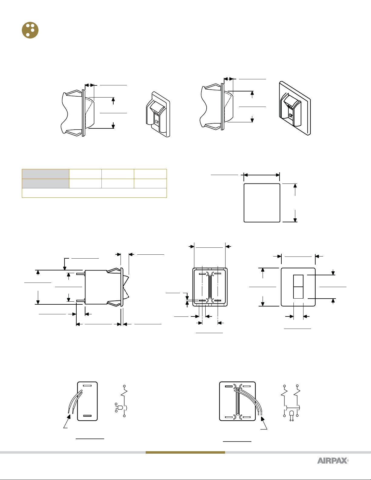
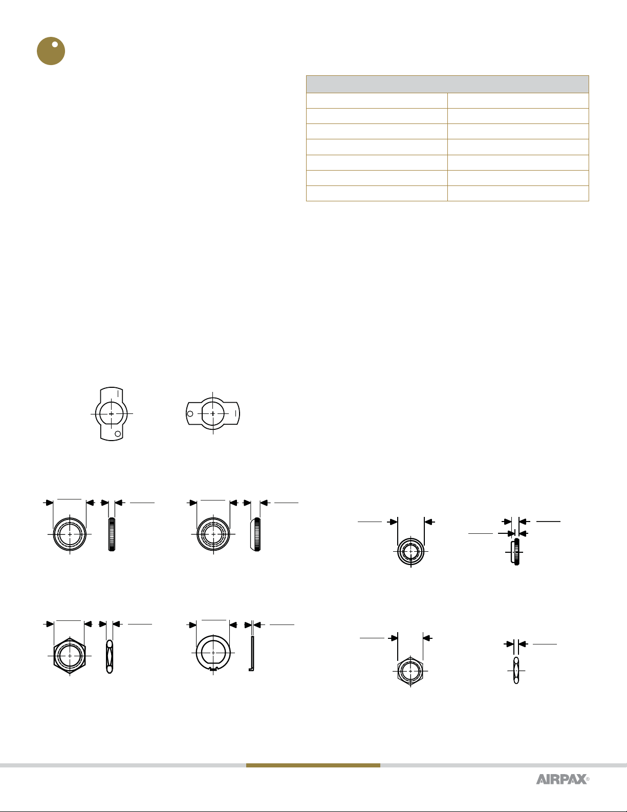
TOGGLE ACTUATORS
Mounting Tolerance ± .005 [.13] unless noted angles: ±5°. Dimensions in
Brackets [ ] are millimeters
[12.70 ± ]
.025
.000
.500 ±
.010
.000
.355
[9.02]
.125
[3.18]
Mounting Details with Locking Ring
[12.70 ± ]
.025
.000
.500 ±
.010
.000
.222 ± 0.002
[5.64 ± 0.05]
PANEL CUTOUT SHOWN ABOVE
MAY BE MADE WITH GREENLEE
RADIO CHASSIS PUNCH #733 x 1/2” DIA.
without Locking Ring
The SNAPAK® is available with paddle handles
in six attractive colors. Engineered for safe, sure
operation, the paddle handles may be specified in

www.sensata.com
Page 2
Copyright © 2020 Sensata Technologies, Inc.
ROCKER HANDLES WITH ILLUMINATION
SNAPAKs are offered in single and two pole rocker styles in a choice of black,
white or gray body colors. Handle color in non-illuminated types may be black,
red, white or orange. Neon or light emitting diode (LED) illumination may be
specified with a variety of options.SNAPAK® circuit protectors with a second
pole are available in paddle handle, push-pull, push-to-reset and rocker handle
versions.
15º
15º
ON
OFF
FLAT
1.715 ± 0.030
[43.56 ± 0.76]
.375 ± 0.010
[9.53 ± 0.25]
1.125 ± 0.030
[28.58 ± 0.76]
.125 ± 0.010
[3.17 ± 0.25]
.468 ± 0.010
[11.89 ± 0.25]
0.500 ± 0.030
[12.70 ± 0.76]
1/2 - 32 THD
.680 ± 0.010
[17.27 ± 0.25]
.031
[0.79]
.250
[6.35]
1.375 ± 0.010
[34.93 ± 0.25]
1 LINE
2
Single Pole, Toggle
24
1 LINE LINE 3
POLE 1 POLE 2
15º
15º
ON
OFF
FLAT
1.715 ± 0.030
[43.56 ± 0.76]
.375 ± 0.010
[9.53 ± 0.25]
1.125 ± 0.030
[28.58 ± 0.76]
.125 ± 0.010
[3.17 ± 0.25]
.468 ± 0.010
[11.89 ± 0.25]
0.500 ± 0.030
[12.70 ± 0.76]
1/2 - 32 THD
.625 ± 0.010
[15.88 ± 0.25]
.031
[0.79]
.250
[6.35]
1.375 ± 0.010
[34.93 ± 0.25]
1.304 ± 0.010
[33.12 ± 0.25]
Two Pole, Toggle
Paddle Handle
Paddle Handle
Rocker, Single Pole
0.093 ± 0.010
[2.36 ± 0.25]
0.125 ± 0.010
[3.18 ± 0.25]
0.030 ± 0.325
[8.26 ± 0.76]
0.680 ± 0.010
[17.27 ± 0.25]
0.031
[0.79]
0.250
[6.35]
1.840 ± 0.030
[46.74 ± 0.76]
0.375 ± 0.010
[9.53 ± 0.25]
1.125 ± 0.030
[28.58 ± 0.76]
1.375 ± 0.010
[34.93 ± 0.25] 0.972 ± 0.010
[24.69 ± 0.25]
1.560 ± 0.010
[39.62 ± 0.25]
0.400 ± 0.010
[10.16 ± 0.25]
0.770 ± 0.010
[19.56 ± 0.25]
ON
OFF
2
1 LINE
Mounting Detail
DIM. A
(SEE TABLE)
[18.03 ± ]
.025
.000
.710 ±
.010
.000
www.sensata.com
Page 3
Copyright © 2020 Sensata Technologies, Inc.
Panel Thickness 0.125 [3.18] 0.093 [2.36] 0.062 [1.57]
Dimension “A” 1.460 [37.08] 1.420 [36.07] 1.385 [35.18]
Note: Tolerance for Mtg. ± .005 (.13)58
The SNAPAK® circuit protector is available with an optional handle guard as an integrated part of the snap-in mounting design. Available for rocker
actuators, the guard helps in providing protection from accidental “turn-off.” Please refer to the SNAPAK® Part Number Decision Tables; fourth
decision.
HANDLE GUARDS
1.047 ± 0.010
[26.60 ± 0.25]
0.305 ± 0.010
[7.75 ± 0.25]
Handle Guards, Single Pole Handle Guards, Two Pole
1.047 ± 0.010
[26.60 ± 0.25]
0.305 ± 0.010
[7.75 ± 0.25]
0.093 ± 0.010
[2.36 ± 0.25] 0.625 ± 0.010
[15.88 ± 0.25]
0.125 ± 0.010
[3.18 ± 0.25]
0.030 ± 0.325
[8.26 ± 0.76]
1.304 ± 0.010
[33.12 ± 0.25]
0.031
[0.79]
0.250
[6.35]
1.840 ± 0.030
[46.74 ± 0.76]
0.375 ± 0.010
[9.53 ± 0.25]
1.125 ± 0.030
[28.58 ± 0.76]
1.375 ± 0.010
[34.93 ± 0.25] 0.972 ± 0.010
[24.69 ± 0.25]
1.560 ± 0.010
[39.62 ± 0.25]
0.400 ± 0.010
[10.16 ± 0.25]
1.394 ± 0.010
[35.41 ± 0.25]
24
1 LINE LINE 3
POLE 1 POLE 2
ON
OFF
Rocker, Two Pole
LOAD
LINE
1 LINE
2
7.00 ± 0.50
[177.8 ± 12.7]
RED (+), BLACK(–)
24
1 LINE LINE 3
7.00 ± 0.50
[177.8 ± 12.7]
RED (+), BLACK (-)
LINE
LOAD
Illuminated Handle
Single Pole
Two Pole
Mounting Detail
DIM. A
(SEE TABLE)
[33.76 ± ]
.025
.000
1.329 ±
.010
.000
FRONT SNAP-IN MOUNT (STD)
www.sensata.com
Page 4
Copyright © 2020 Sensata Technologies, Inc.
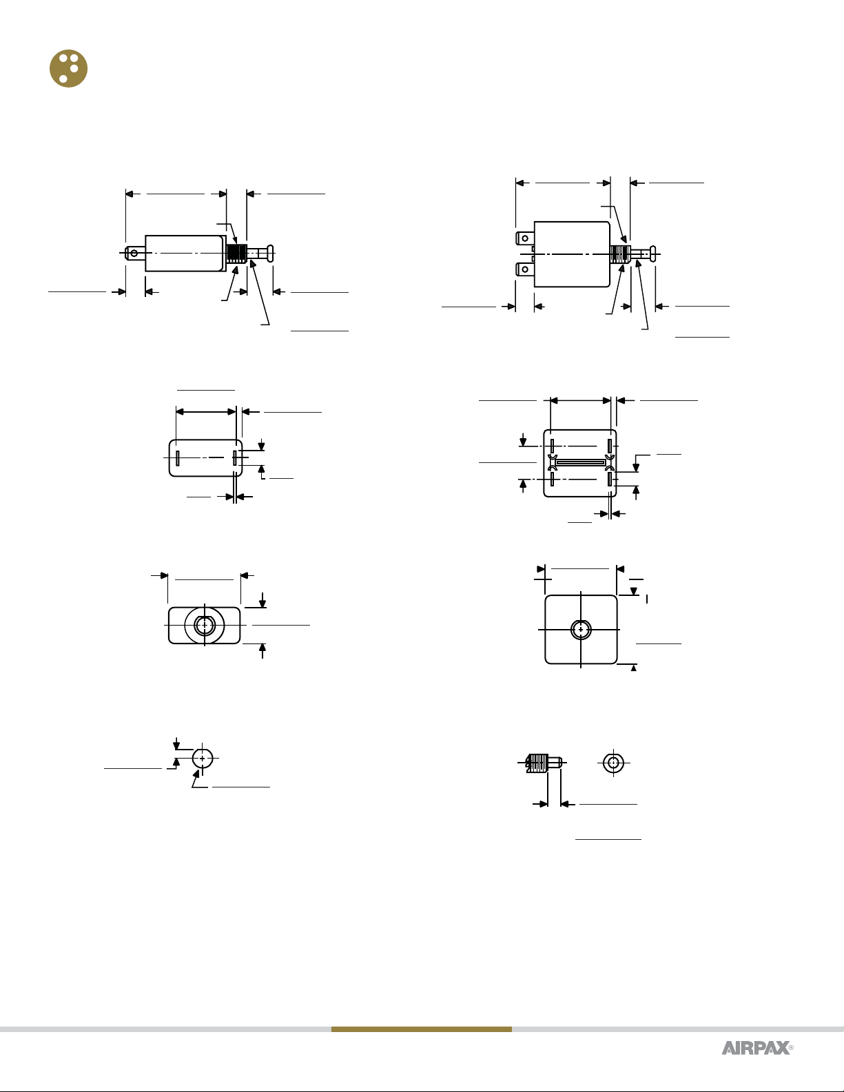
SNAPAK® may also be ordered with Push-Pull, or Push-to-Reset actuator buttons. As an option, the button can be embossed with the current rating
(Push-Pull option only).
PUSH-PULL, PUSH-TO-RESET ACTUATOR
1.375 ± 0.010
[34.93 ± 0.25]
.680 ± 0.010
[17.27 ± 0.25]
2
1 LINE
.125 ± 0.010
[3.18 ± 0.25]
1.125 ± 0.030
[28.58 ± 0.76]
.250
[6.35]
.031
[.79]
24
1 LINE LINE 3
POLE 2
POLE 1
.625 ± 0.010
[15.88 ± 0.25]
1.125 ± 0.030
[28.58 ± 0.76]
.125 ± 0.010
[3.18 ± 0.25]
.250
[6.35]
.031
[.79]
1.375 ± 0.010
[34.93 ± 0.25]
1.304 ± 0.010
[33.12 ± 0.25]
[9.53 ± ]
.025
.000
.375 ±
.010
.000
.162 ± 0.002
[4.11 ± 0.05]
0.76 ± 0.030 OFF
[6.35 ± 0.25]
FLUSH ± 0.030 ON
[FLUSH ± 0.25]
Mounting Detail
(Single Pole and Two Pole)
Push-to-Reset Actuation
(Single and Two Pole)
Push-Pull, Single Pole
1.960 ± 0.030
[49.78 ± 0.76]
.375 ± 0.010
[9.53 ± 0.25]
.400 ± 0.010
[10.16 ± 0.25]
0.500 ± 0.030
[12.70 ± 0.76] OFF (SHOWN)
0.250 ± 0.030
[6.35 ± 0.76] ON
WHITE BAND VISIBLE
IN OFF POSITION ONLY
3/8 - 32 THD
FLAT
Push-Pull Actuation
1.960 ± 0.030
[49.78 ± 0.76]
.375 ± 0.010
[9.53 ± 0.25]
.400 ± 0.010
[10.16 ± 0.25]
0.500 ± 0.030
[12.70 ± 0.76] OFF (SHOWN)
0.250 ± 0.030
[6.35 ± 0.76] ON
WHITE BAND VISIBLE
IN OFF POSITION ONLY
3/8 - 32 THD
FLAT
Push-Pull, Two Pole
Push-Pull Actuation
Note:
Tolerance ± .005 [.13] unless noted angles: ±5˚.
Dimensions in Brackets [ ] are millimeters.

www.sensata.com
Page 5
Copyright © 2020 Sensata Technologies, Inc.
SCREW TERMINALS
Available as straight screw terminals with UNC 8-32 and Metric M4 screw types, bus-type connect (flat) or upturned lugs (tabs), with UL, CSA and TÜV
approvals available.
Screw terminals are available for all handle options (rocker, toggle, push-pull, push-to-reset). Single pole only, series only, non-auxiliary switch
configurations.
(SEE TABLE)
DIM. “A”
Toggle
(SEE TABLE)
DIM. “A”
Push Button
(SEE TABLE)
DIM. “A”
Rocker Straight
1.067
[27.11]
0.374
[9.50]
0.597
[15.16]
DIMENSION “A
Handle Style Screw Terminal “A” Dimension
Toggle Straight 1.773 [45.03]
Push Button Straight 2.180 [55.37]
CONFIGURATIONS
Series Trip
The most popular configuration for magnetic protectors is the series
trip where the sensing coil and the contacts are in series with the
load being protected. In addition to providing conventional overcur-
rent protection, it is simultaneously used as an on-off switch.
Shunt Trip
The shunt trip is designed for controlling two separate loads with one
assembly. The control is established by providing overload protection
for the critical load. When the current through this load becomes
excessive and reaches the trip point, the protector will open and
remove power from both loads simultaneously. The current rating of
both loads must not exceed the maximum contact rating.
Relay Trip
This permits the overload sensing coil to be placed in a circuit which
is electrically isolated from the contacts. The coil may be actuated
by sensors monitoring pressure, flow, temperature, speed, etc. Other
typical applications include crowbar, interlock and emergency/rapid
shutdown circuitry. Trip may be accomplished by voltage or current,
which must be removed after trip.
LOAD
LINE
1 LINE
2
LOAD
LINE
24
1 LINE LINE 3
Series Trip
Single Pole
Two
Pole
SHUNT
LOAD
LINE
7.00 ± 0.50
[177.8 ± 12.7]
WHITE LEAD
LOAD SHUNT
LOAD
LINE
24
1 LINE LINE 3
7.00 ± 0.50
[177.8 ± 12.7]
WHITE LEAD
Shunt Trip
Single Pole
Two Pole
( 1 pole shunt)
LOAD
COIL
COIL
LINE
1 LINE
2
7.00 ± 0.50
[177.8 ± 12.7]
WHITE LEAD
24
1 LINE LINE 3
LOAD
COIL
COIL
LINE
7.00 ± 0.50
[177.8 ± 12.7]
WHITE LEAD
Two Pole
(1 pole relay)
Relay Trip (Note A)
Single Pole
Note A: Coil Ratings to 5 amperes maximum. Contact ratings are 7.5
amperes at 50 Vdc and 250 Vac; 15 amperes at 120 Vac; 32 Vdc.
Tolerance ± .005 [.13] unless noted. Dimensions in Brackets [ ] are
millimeters.

www.sensata.com
Page 6
Copyright © 2020 Sensata Technologies, Inc.
Auxiliary Switch
This is furnished as an integral part of a series pole in single or,
multi-pole assemblies. Isolated electrically from the protector s
circuit, the switch works in unison with the power contacts and
provides indication at a remote location of the protector’s ON-OFF
status.
Voltage Trip
Sometimes called “dump circuits” or “panic trip circuits,” these units
make it possible to open main power contacts with lower power
inputs from one or more sources. This configuration is becoming
increasingly more important for sensitive circuitry and denser
packaging in automation systems. Available in series, shunt or relay
configurations.
Power Switch
In the event that over-current protection is not desired, the coil
mechanism can be deleted, providing an excellent low cost single or
double-pole power switch. Maximum current rating is 20 amps.
24
1 LINE LINE 3
C
N
C
N
O
0.093
[2.36]
0.040 [1.02] DIA. HOLE
(FOR SOLDER ATTACHMENT)
.560 ± 0.030
[1 4.22 ± 0.76 ]
LOAD
LINE
BREAKER SHOW N
IN OFF POSITION
C
NC
NO
LOAD
LIN E
BREAKER SHO WN
IN OFF POSITION
NC
NO
C
.100 to 20.0 amps,
NON-VDE &
NON-TÜV >20amps
VDE, T ÜV >20amps
& U3 Construction
2
1 LINE
C
N
C
N
O
0.093
[2.36]
0.040 [1.02] DIA. HOLE
(FOR SOLDER ATTACHMENT)
.560 ± 0.030
[1 4.22 ± 0.7 6]
LOAD
LINE
BREAKER SHOW N
IN OFF POSITION
C
NC
NO
LOAD
.100 to 20.0 amps,
NON-VDE &
NON-TÜV >20amps
VDE, TÜ V >20amps
& U3 Construction
LINE
BREAKER SHOW N
IN OFF POSITION
NC
NO
C
Auxiliary Switch (Note B)
Single Pole
Auxiliary Switch (Note B)
Two Pole
Note B: Switch is located in the left hand pole (viewed from terminal end).
www.sensata.com
Page 7
Copyright © 2020 Sensata Technologies, Inc.
OPERATING CHARACTERISTICS
Inrush Pulse Tolerance
Many circuit protector applications involve a transformer turn-on, an incandescent lamp load, or a capacitor charge from a DC source. Each of these
applications has one common factor: a steep transient of very high current amplitude and short duration. This takes the form of a spike or a single pulse
and is the cause of most nuisance tripping associated with magnetic circuit breakers.
SNAPAK® will withstand, without tripping, a single pulse of 8 milli-seconds duration (half sine wave configuration) and peak amplitude of 9 times its
rating without the inertia wheel and 13 times its rating with an inertia wheel. (Not applicable to instant trip delays).
MAXIMUM DCR AND IMPEDANCE
Current Ratings (Amps) T/R/PP/PR DC Resistance T/R/PP/PR 50/60Hz Impedance CR/CPP/CPR DC Resistance
.100 175 181 274
.500 6.34 6.63 9.77
1.00 1.63 1.69 2.31
2.00 .400 .425 .465
3.00 .175 .188 .261
4.00 .103 .106 .156
5.00 .076 .078 .091
7.50 .038 .039 .053
10.0 .026 0.28 .023
12.5 .020 0.21 .020
15.0 .013 .014 .010
20.0 .010 .011 .008
25.0 .004
30.0 .003
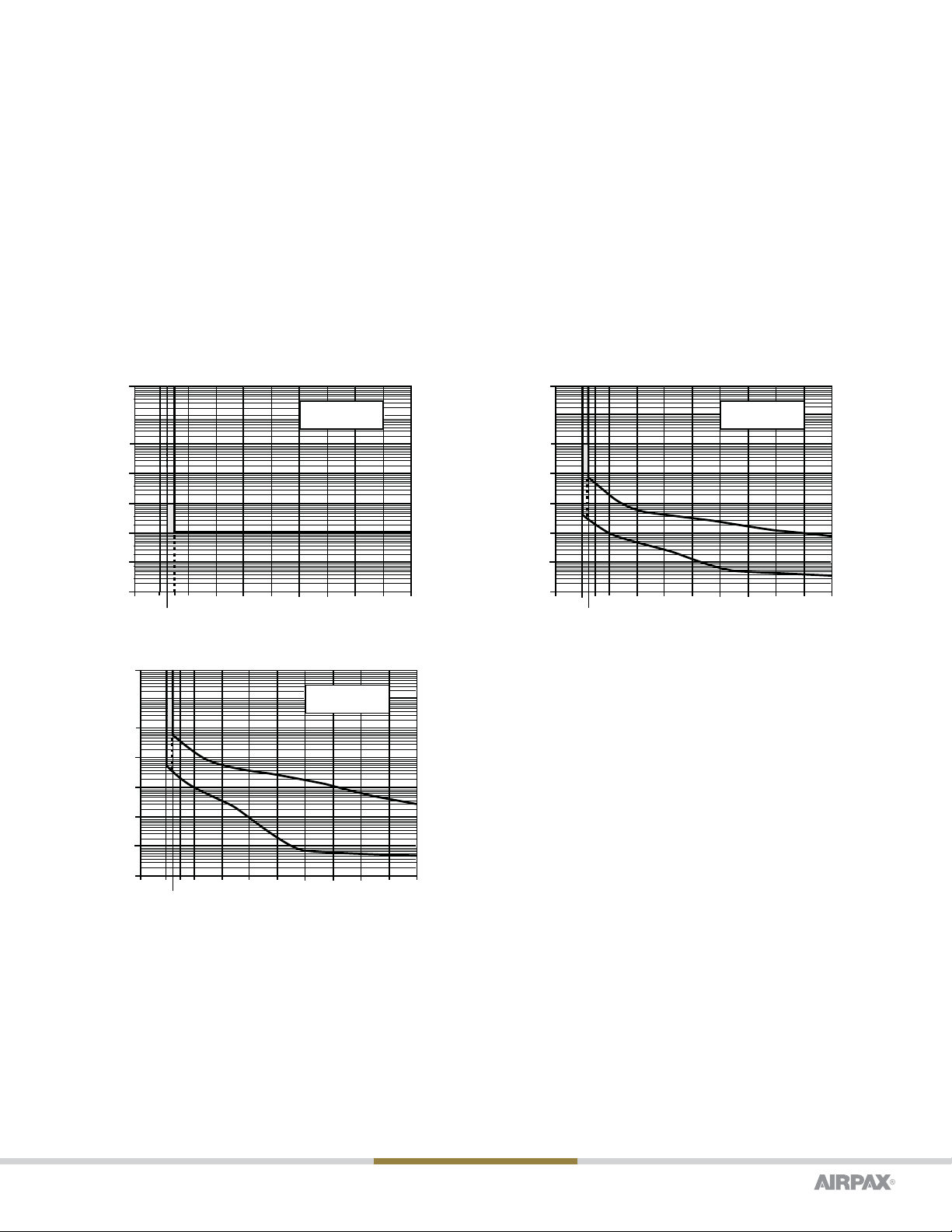
PERCENTAGE OF RATED CURRENT VS TRIP TIME IN SECONDS AT +25°C (VERTICAL MOUNT)
Delay 100% 135% 150% 200% 400% 600% 800%
Instant No Trip May Trip .100 Max .100 Max .100 Max .100 Max .100 Max
Fast No Trip .3 to 7 .2 to 5 .1 to 2 .03 to .50 .015 to .30 .010 to .150
Slow No Trip 3 to 70 2 to 40 1 to 15 .10 to 4.0 .015 to 2.0 .010 to .800
PULSE TOLERANCE
Delay Pulse Tolerance
1, 2, 61, 62 *9 Times Rated Current
3, 4, 61F, 62F *13 Times Rated Current
400 Hz, DC, 50/60Hz Delay Curves (typ)
A choice of delays is offered for DC, 50/60Hz and 400Hz applications. Delays 0, 49, 59 and 69 provide fast-acting, instantaneous trip and are often
used to protect sensitive electronic equipment (not recommended where known inrush exists). Delays 1, 41, 51 and 61 have a short delay for general
purpose applications. Delays 2, 42, 52 and 62 are long enough to start certain types of motors and most transformer and capacitor loads.
Trip Free
Will trip open on overload, even when forcibly held on.This prevents operator from damaging the circuit by holding handle in the ON position.
Trip Indication
The operating handle moves forcibly and positively to the OFF position on overload.
DELAY CURVES & SPECIFICATIONS
DCR and Impedance is measured after 1 hour at 100% rated current using the Voltmeter-Ammeter Method
* Units above 15 amps are derated to 8 and 12 times rated current
* Minimum trip for all instantaneous and 400Hz units.
www.sensata.com
Page 8
Copyright © 2020 Sensata Technologies, Inc.
10000
1000
100
10
1
.1
.01
.001
0 100 150 200 300 400 500 600 700 800 900 1000
PERCENT OF RATED CURRENT
135
TIME IN SECONDS
INSTANT
MAY TRIP
10000
1000
100
10
1
.1
.01
.001
0 100 150 200 300 400 500 600 700 800 900 1000
PERCENT OF RATED CURRENT
135
TIME IN SECONDS
FAST
MAY TRIP
10000
1000
100
10
1
.1
.01
.001
0 100 150 200 300 400 500 600 700 800 900 1000
PERCENT OF RATED CURRENT
135
TIME IN SECONDS
SLOW
MAY TRIP
Ambient Operation
Operates normally in temperatures between –40° C and +85°C.
Insulation Resistance
Not less than 100 megohms at 500Vdc.
Dielectric Strength
Withstands 1500 volts, 60Hz for 60 seconds or 1800Vac for one second between all electrically isolated terminals.
Endurance
Mechanical life in excess of 50,000 operations. In manyapplications, however, contact wear due to the electrical load determines unit life. At
maximum electrical ratings, the SNAPAK® can perform 10,000 operations at rated current and voltage. Under UL 1077, the SNAPAK® can perform
50 operations at 150% of maximum rated current followed by 6,000 operations at maximum rated current. Under EN60934 the SNAPAK® can
perform 6,000 electrical operations. After any endurance cycle, the breaker will calibrate and have working
www.sensata.com
Page 9
Copyright © 2020 Sensata Technologies, Inc.
HARDWARE
Indicator Plates
SNAPAK® toggle handle circuit protectors may be specified with
indicator plates for either vertical or horizontal mounting.The “ON-
OFF/O-I” plate is standard.
Note 1:To allow for installation clearances, the minimum recommend-
ed distances between centers of panel openings should be:
RECOMMENDED CENTER DISTANCES FOR PANEL OPENINGS
Breaker Type Distance, inches [mm]
T11 0.750 [19.05]
T21 1.375 [34.93]
PP11 & PR11 0.750 [19.05]
PP21 & PR21 1.375 [34.93]
R11 0.805 [20.45]
R21 1.429 [36.30]
Note 2: Torque on mounting hardware is not to exceed 25 inch-pounds for 1/2 inch bushings or 15 inch-pounds for 3/8 inch bushings.
Mounting Nuts (Toggle)
A choice of knurled, dress and hex nuts are available. All three are available in bright nickel. The knurled and dress nuts are also available in a matte
black finish. Every SNAPAK® comes with a hex nut, but you may order the front panel nuts which will best enhance your design.
Miscellaneous Hardware
SNAPAK® circuit protectors with 1/2-32 thread may also be equipped with optional locking rings to prevent rotation of the unit after it is installed.
3/8 - 32 Hex Nut and Panel Nuts
The hardware will be supplied with each Push-Pull (PP) and Push-to-Reset (PR).
3/8 - 32 Panel Nut
This nut when reversed will provide alignment in .437 (11.1) and .468 (11.88) diameter round panel holes.
ON
OFF
– A
Vertical Mount
– B
O
F
F
O
N
Horizontal Mount
Paddle Handle Hardware
– 10 & –11
0.125
[3.18]
0.680
[17.27]
– 20 & –21
0.180
[4.57]
0.680
[17.27]
Knurled Nut Panel Dress Nut
– 31
0.125
[3.18]
0.625
[15.88]
Hex Nut
– L
0.031
[0.79]
0.680
[17.27]
Locking Ring (Toggle)
0.078
[1.98]
0.534
[13.56]
0.156
[3.96]
3/8 - 32 Panel Nut
Bright Nickel
Note: Tolerance ± .010 [.25] unless noted. Dimensions in brackets [ ] are millimeters.
Push-Pull & Push-to-Reset Hardware
0.500
[12.7] 0.156
[3.96]
3/8 - 32 Hex Nut
Bright Nickel

www.sensata.com
Page 10
Copyright © 2020 Sensata Technologies, Inc.
ORDERING OPTIONS Example: T11-2-5.00A-01-11AL-V
T11 -2-5.00A -01 -11AL -V
The ordering code for the SNAPAK® circuit protectors may be determined by following the steps in the decision tables shown here.
The coding given permits a self-assigning part number, with certain limitations (due to the adaptability of magnetic protectors to complex circuits),
requires a factory-assigned part number.
The example shown is the code for a paddle handle, single pole (ULconstruction), series circuit protector designed for operation of a 50/60Hz/ DC
circuit. A slow tim delay and rating of 5 amperes has beenindicated. Handle color is black, and a bright nickel knurled nut, vertical mount (ON-OFF)
indicator plate and locking ring are to be supplied.
To determine the ordering code for your particularSNAPAK® unit, simplyfollow the steps shown,then fill in the letters and/or numbers in the boxes.
Space is available on the circuit breaker label for your part number (up to 12 digits). You may then use your own part number to place an order or as a
reference for further questions you may have.
This option does require a factory assigned part number for traceability to your drawing or internal part number.
Type
Handle Poles Configurations* Terminals
T: Paddle Handle 1: Single Pole †0: Switch Only (Note E) Quick Connects (leave blank)
PP: Push-Pull 4: Single Pole †† 1: Series Circuit Protector S: Screw Terminals, Single
pole (-1) and series only
(5th decision, group V -
screw terminal option is
required when 1st decision
“S” is specified)
PR: Push-To-Reset 2: Two Pole † 3: Shunt Circuit Protector
R: Rocker 5: Two Pole †† 4: Relay Circuit Protector ††††
CR: Rocker ** 5: Series w/ Silver Aux. Switch †††
CPP: Push-Pull ** 6: Series w/ Gold Aux. Switch †††
CPR: Push to Reset ** 9: Mixed Construction (2 Pole Only)
†UL & CSA Construction
†† Non UL & CSA Construction
††† Auxilary Switch is located in the left hand pole (viewed from terminal end)
†††† Does not meet spacings for many IEC / TUV equipment specs.
Consult factory for additional information.
* Multi-pole units with mixed construction, poles numbered left to right when viewed from terminal end. Shunt or relay construction available in pole 2 only, other pole must be a
series or switch only construction.
**UL 489A listed, available in 1 pole series or series w/silver aux. switch. DC delay only
Frequency & Delay
-0: Instant DC-50/60 Hz
-1: Fast DC-50/60 Hz
-2: Slow DC-50/60 Hz
-3: Fast w/ Inertia Wheel DC-50/60 Hz
-4: Slow w/ Inertia Wheel DC-50/60 Hz
-41* Fast 400 Hz***
-42* Slow 400 Hz*
-49* Instant 400 Hz
-51: Fast DC+
-52: Slow DC+
-59: Instant DC+
-61: Fast 50/60 Hz*
-62: Slow 50/60 Hz*
-69: Instant 50/60 Hz
-S: Switch Pole or Special Delay
* 20 amps max for 400Hz
**For addition of Inertia Delay an “F” may be added to delay 41, 42, 51, 52, 61, 62 only
+CR, CPP, CPR only available in these delays
Rated Current
Circuit Breaker Construction
Use three numbers to print required current value between .100 amps minimum and 30.0 amps maximum.
For example, use: .100 or 2.00 or 10.0
Switch Only Construction
-SW: Maintained SPST & DPST
Note: 20.0 amps max for 400 Hz units.

www.sensata.com
Page 11
Copyright © 2020 Sensata Technologies, Inc.
Rocker
Step 1: Choose Letter For Body Color
B: Black
G: Gray
W: White
R: Black w/ Handle guard
S: Gray w/ Handle guard
T: White w/ Handle guard
Example: “W...”For White Rocker Body
(Rocker Style)
Step: 2: Choose Handle Combinations
Without Illumination Basic Handle Color
(w/o Markings)
01: Black
02: Red
06: White
07: Orange
108: Clear w/4-8 Vdc Green LED
109: Clear w/8-16 Vdc Green LED
121: Transparent Red w/Neon (Note A)
123: Transparent Red w/Red LED (Note B)
124: Transparent Red w/Red LED 4-8 Vdc
125: Transparent Red w/Red LED 8-16 Vdc
161: Translucent White w/Neon (Note A)
162: Translucent White w/ Green Glow Neon (Note A)
171: Transparent Amber w/Neon (Note A)
181: Transparent Smoke Gray w/Neon (Note A)
182: Transparent Smoke Gray w/Green Glow Neon (Note A)
183: Transparent Smoke Gray w/Red LED (Note B)
184: Transparent Smoke Gray w/4-8 Vdc Red LED
185: Transparent Smoke Gray w/8-16 Vdc Red LED
187: Transparent Smoke Gray w/Green LED (Note B)
188: Transparent Smoke Gray w/4-8 Vdc Green LED
189: Transparent Smoke Gray w/8-16 Vdc Green LED
Example: “-W124” If you prefer NO markings, then your handle decision is now complete.
Step 3: Choose Handle Markings
Marked For Vertical Mount-After choice of 3
digit number in step 2 above.
Add “CV ”
for Combined
markings .
ON
I
O
OFF
Add “IV ”
for Intíl.
markings .
I
O
Add “EV ”
for English markings.
Example: "-W124EV "
ON
OFF
Marked For Horizontal Mount-After choice of 3 digit number in step 2 above.
ON
I
Add “CH ”
for Combined
markings .
Add “IH ”
for Internationa l
markings.
O
Add “EH ”
for Englis h
markings .
Example “-W06EH ”
OFF
O
ON
OFF
I
If you have chosen a handle from this table, your 4th Decision and yourcatalog part number are now complete
(except if you require “-S” screwterminal option from the 5th Decision Table.)
Paddle (T) Handle Color
-01: Black
-02: Red
-03: Yellow
-04: Green
-05: Blue
-06: White
If you have chosen a handle from this table, your 4th Decision is now
complete except for hardware options in 5th Decision Table
Push-Pull (PP, CPP and CPR)
-XX: -XX No button markings desired (not available for CPP & CPR)
-OA:
LINE
5Marked buttons available for these amperages
-OB:
LINE
5
0.1
.25
0.5
.75
1
2.5
5
7.5
10
15
17.5
20
-OC:
LINE
5
If you have chosen a handle from this table, your 4th Decision & your catalog PN are now complete (except if you require “-S”
screw terminal option from the 5th Decision Table.)
Push-to-Reset (PR)
-XX: No Button Markings Only
If you have chosen a handle from this table, your 4th Decision and your catalog PN are now complete (except if you require “-S” screw terminal
option from the 5th Decision Table.)
Hardware & Accessories (Notes C and D)
Group I Group II (Indicator Plate) Group V (Screw Terminal Options)
-00: No Outer Hardware Desired
-10: Black Knurled Nut
-11: Bright Nickel Knurled Nut
-A: Vertical Mount (Off/On & O/I)* -C: SAE 8-32, Upturned Lugs (Tabs) Straight Terminal
-D: SAE 8-32, Bus-Type Connect (Flat) Straight Terminal
-F: M4, Upturned Lugs (Tabs) Straight Terminal
-H: M4, Bus-Type Connect (Flat) Straight Terminal
-20: Black Panel Dress Nut
-21: Bright Nickel Panel Dress Nut
-31: Bright Nickel Hex Nut
-B: Horizontal Mount (Off/On & O/I)*
Group III *Selection of A or B Indicator Plate
required for TUV and CCC.
Please select a screw terminal option if you selected
“S” in Decision 1
-L: Locking Ring
T, V = TÜV and CCC Approved
The shaded areas denote CCC (if applicable) and CE compliant options.
The V will be added to any part number formed entirely from shaded decisions.
If non-shaded areas are selected, the unit will not be approved, nor CE compliant, but other approvals still apply. 20 amps max rating on units.
www.sensata.com
Page 12
Copyright © 2020 Sensata Technologies, Inc.
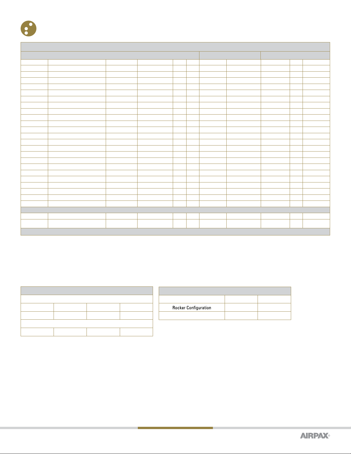
AGENCY APPROVALS & CERTIFICATIONS
All supplementary protectors are of the overcurrent (OC) type
The family of protectors has been evaluated for end use application for use group (UG) A
The terminals (FW) are suitable for factory wiring only (0)
The maximum voltage ratings for which the protectors have been tested are shown in the chart
The current is the amperage range that the protectors have been tested
The tripping current (TC) for the protectors is either “1” (in the range of 125% to 135% of ampere rating) or “2” (more than 135% of ampere rating)
The overload rating (OL) – designates whether the protector has been tested for general use or motor starting applica-tions.
0 – tested at 1.5 times amp rating for general use
1 – tested at 6 times AC rating or 10 times DC rating for motor starting
The short circuit current rating (SC) – The short circuit rating in amperes following a letter and number designating the test conditions and any calibration following the short circuit test is defined below:
AUXILIARY SWITCH RATING
Silver
3.0 amps @ 120 VAC –––
1.5 amps @ ––– 32 VDC
Gold
.100 amps @ 32 VAC 32VDC
APPROXIMATE WEIGHT PER POLE
Ounces Grams
0.9 25
Toggle, PP, PR 1.2 32
C – Indicates short circuit test was conducted with series overcurrent protection
U – Indicates short circuit test was conducted without series overcurrent protection
1 – Indicates a recalibration was not conducted as part of the short circuit testing
2 – Indicates a recalibration was performed as part of the short circuit testing
3 – Indicates recalibration was performed along with the dielectric and voltage withstand for “Suitable for
Further Use” rating
Short Circuit Interrupting Capacity1000 amperes maximum for UL and CSA, 500 amperes maximum for
TUV. Consult factory for details.
Handle and Body
Material The handle and upper body material is polycarbonate and the lower body is PET. Chemical
Resistance
Handle and case may be cleaned with detergents or alcohols and should be restricted to outside surfaces
only.
Organic solvents are not recommended. Special attention should be given when solvents are used to
remove excess flux from terminals. No oils or lubricants should be introduced into handle openings or onto
bushing threads.
IEC, UL, CSA, SEV, VDE, CCC, CE, TÜV
Recognized by UL to STD-1077 and UL certified to spacing requirements of IEC 950 for basic and functional
Voltage Frequency (Hz) Phase Min. PolesT CO L UL/CSA TUV UL 1077 & CSA TUV Notes
32 DC -1 10 .10-30(3) .10-20 U1, 1000 500
38 DC -1 10 .10-15- U2, 1000 / U1, 1000 -P R only
65 DC -1 10 .10-7.5 -U 2, 500 /U1, 500 -
65 DC -2 10 .10-15- U1, 1000-
65 DC -2 10 .10-20. 10-20 U2, 500 / U1, 5005 00
65(2)D C- 11 0 .10-30. 10-30 U2, 120 120R , PP, PR only
65(2)D C- 2 only 10 .10-25- U1, 100 -R only
65(2)D C- 21 0 .10-25- U2, 500 -R only
125 50/60 11 10 .10-20 7.6-20 U1, 10005 00
125 50/60 11 10 .10-30(3) - U1, 1000- T only
125(2) 50/60 11 10 .10-30 - U2, 1000- R, PP, PR only
125(2) 50/60 11 11 .10-30 20.1-30 U3, 300(1)5 00 R, PP, PR only
120/240 50/60 12 20 .10-25(3)- U2, 1000-
120/240 50/60 12 20 .10-30(3)- U1, 650 -
125/250 50/60 12 20 .10-20 - U1, 1000-
2505 0/60 11 20 .10-20 .1-7.5 U1, 500 500
2505 0/60 11 10 .10-7.5 -C 1, 1000(4)-
2505 0/60 12 20 .10-20 .10-20 U1, 1000 500
250(2) 50/60 12 11 .10-30 -U 3, 300 -R only
1254 00 11 20 .10-20 -U 1, 1000 -
125/250 4001 22 0. 10-20 -U 1, 1000 -
250 4001 22 0. 10-20 -U 1, 1000 -
250 4001 12 0. 10-7.5- U1, 1000 -
CR/CPP/CPR COMMUNICATIONS EQUIPMENT CIRCUIT BREAKERS
65 DC -1 only -- .10-30 .10-301 000 1000
80 DC -1 only -- .10-30 .10-306 00 600
(1) Non-standard construction. “Fit For Further Use” approval; (2) Non-snap action design; (3) No auxiliary switch available above 20A; (4) With 30A max. series fuse
AGENCY APPROVALS (T/P/PP/PR SUPPLEMENTARY PROTECTORS)
Voltage (Volts), Frequency (hz), Phase, Min Poles, TC, OL Current (Amps) Short Circuit Current Rating (Amps)
insu-lation for front panel mounting. Certified by CSA, file number LR26229 as recognized supplementa-
ry protectors, SEV approved, CCC approved, TÜV approved (including screw terminals) to EN60934. TUV
approval of unmarked rocker handle option for appliance disconnect requires status of protectors to
be indicated on the panel. Only TUV approved part numbers will be marked CE compliant. See shaded
areas of part number decision tables for approved configurations and/or consult factory for exceptions
and limitations.
Shock
Withstands 75G without tripping while carrying full rated current per MIL-STD-202, Method 213, Test
Condition I. Instant trip breakers are tested at 80% of rated current.
Vibration
Time delayed units withstand 10G without tripping while carrying full rated current per MIL-STD-202,
Method 204, Test Condition A. Instant trip breakers are tested at 80% of rated current.UL 489A List-
edThe CR, CPP and CPR are dimensionally the same as the popular R, PP and PR Snapack products, but
provide UL listing to UL489A for Communications Equipment. Available only in single pole with DC trip
time delays for series or series with silver auxiliary switch configurations. As a circuit breaker, the CR,
CPP or CPR provides communication equipment manufacturers with a UL listed circuit breaker in an ex-
tremely compact package that meets the stringent environmental requirements of today’s marketplace.
This makes the CR, CPP and CPR ideal for switching, transmission and wireless applications.
Page 13
www.sensata.com
CONTACT US
Americas
508-236-2551
electrical-protection-sales@
sensata.com
Europe, Middle East & Africa
+31743578156
Asia Pacific
China +86 (21) 2306 1500
Japan +81 (45) 277 7117
Korea +82 (31) 601 2004
India +91 (80) 67920890
Rest of Asia +886 (2) 27602006
ext 2808
Copyright © 2020 Sensata Technologies, Inc.
Sensata Technologies, Inc. (“Sensata”) data sheets are solely intended to assist designers (“Buyers”) who are developing systems that
incorporate Sensata products (also referred to herein as “components”). Buyer understands and agrees that Buyer remains responsible
for using its independent analysis, evaluation and judgment in designing Buyer’s systems and products. Sensata data sheets have
been created using standard laboratory conditions and engineering practices. Sensata has not conducted any testing other than that
specifically described in the published documentation for a particular data sheet. Sensata may make corrections, enhancements,
improvements and other changes to its data sheets or components without notice.
Buyers are authorized to use Sensata data sheets with the Sensata component(s) identified in each particular data sheet. HOWEVER, NO
OTHER LICENSE, EXPRESS OR IMPLIED, BY ESTOPPEL OR OTHERWISE TO ANY OTHER SENSATA INTELLECTUAL PROPERTY RIGHT, AND
NO LICENSE TO ANY THIRD PARTY TECHNOLOGY OR INTELLECTUAL PROPERTY RIGHT, IS GRANTED HEREIN. SENSATA DATA SHEETS
ARE PROVIDED “AS IS”. SENSATA MAKES NO WARRANTIES OR REPRESENTATIONS WITH REGARD TO THE DATA SHEETS OR USE
OF THE DATA SHEETS, EXPRESS, IMPLIED OR STATUTORY, INCLUDING ACCURACY OR COMPLETENESS. SENSATA DISCLAIMS
ANY WARRANTY OF TITLE AND ANY IMPLIED WARRANTIES OF MERCHANTABILITY, FITNESS FOR A PARTICULAR PURPOSE, QUIET
ENJOYMENT, QUIET POSSESSION, AND NON-INFRINGEMENT OF ANY THIRD PARTY INTELLECTUAL PROPERTY RIGHTS WITH REGARD
TO SENSATA DATA SHEETS OR USE THEREOF.
All products are sold subject to Sensata’s terms and conditions of sale supplied at www.sensata.com SENSATA ASSUMES NO LIABILITY
FOR APPLICATIONS ASSISTANCE OR THE DESIGN OF BUYERS’ PRODUCTS. BUYER ACKNOWLEDGES AND AGREES THAT IT IS SOLELY
RESPONSIBLE FOR COMPLIANCE WITH ALL LEGAL, REGULATORY AND SAFETY-RELATED REQUIREMENTS CONCERNING ITS PRODUCTS,
AND ANY USE OF SENSATA COMPONENTS IN ITS APPLICATIONS, NOTWITHSTANDING ANY APPLICATIONS-RELATED INFORMATION
OR SUPPORT THAT MAY BE PROVIDED BY SENSATA.
Mailing Address: Sensata Technologies, Inc., 529 Pleasant Street, Attleboro, MA 02703, USA.
Revised 01/17/20
Notes:
A A neon bulb is provided when specified for 120Vac and 250Vac operation. For operation at 120Vac a 33,000 ohm, 1/2 watt external resistor is
required. At 250Vac a 100,000ohm, 1 watt external resistor is required.
B An LED with 750 ft. L @ 20mA is provided in the center of the handle. Maximum power dissipation @ 25°C is 135mW. Continuous forward current
is 20mA. Forward voltage, typical, is 1.6v at 20mA. Reverse current, typical, is 100mA @ 3.0 volts. An external resistor may be required to limit
current to these values.
C When ordering Paddle Handles, you may choose one item from each hardware group to add to 5th decision if such items are desired. For example,
“-11ALCA” would indicate a bright nickel knurled nut, plus a vertical mount indicator, plus a locking ring, plus #8-32 screw terminal, straight with
tabs.
D All units except Rocker units will have (1) hex nut installed as standard hardware for the back of a panel. The choices in the fifth decision table are
intended for the front or visible side of the panel and are offered for Paddle Handle configuration only. Push-Pull and Push-to-Reset configurations
include one (1) panel nut and one (1) hex nut as standard hardware.
E Switch only — no current overload protection provided.
F. CCC Approval - If CCC is required on this product, please inform Sensata to have this product manufacturered in our China facility
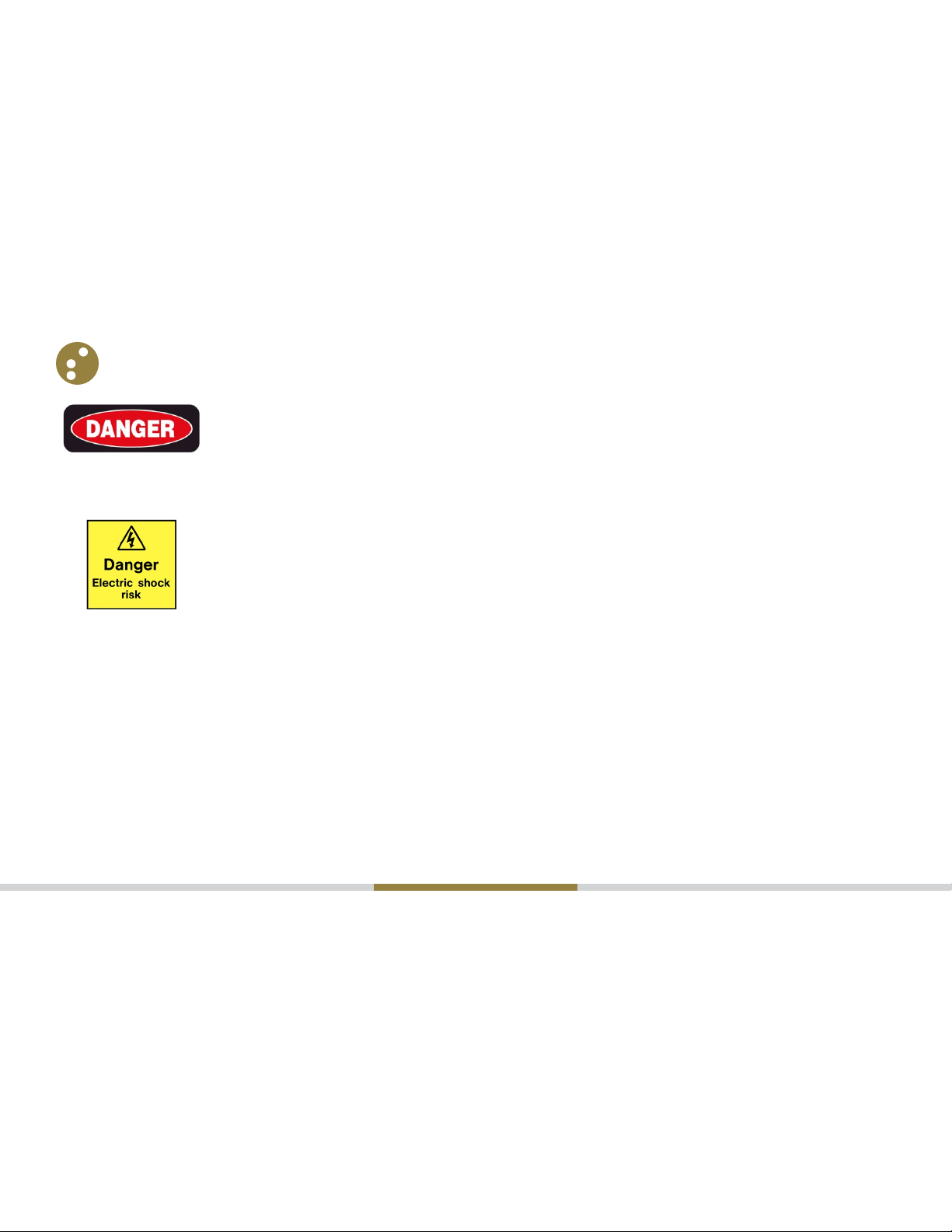
WARNINGS
RISK OF MATERIAL DAMAGE AND HOT ENCLOSURE
• The product’s side panels may be hot, allow the product to cool before touching
• Follow proper mounting instructions including torque values
• Do not allow liquids or foreign objects to enter this product
Failure to follow these instructions can result in serious injury, or equipment damage.
HAZARD OF ELECTRIC SHOCK, EXPLOSION OR ARC FLASH
• Disconnect all power before installing or working with this equipment
• Verify all connections and replace all covers before turning on power
Failure to follow these instructions can result in death or serious injury.
Table of contents
Popular Circuit Breaker manuals by other brands

Eaton
Eaton Power Defense 32-NF Instruction leaflet

Eaton
Eaton DSII Series Instructions for installation, operation and maintenance

Siemens
Siemens JG installation instructions

GE
GE AM-4.16-250-9 instructions

Eaton
Eaton AB De-ion Instruction leaflet

Siemens
Siemens 3VA911 0JC12 Series operating instructions


