GE MicroVersaTrip AKR-75 User manual
Other GE Circuit Breaker manuals

GE
GE SPST480 User manual

GE
GE Spectra K-frame User manual

GE
GE Spectra Series AMC3FGB User manual

GE
GE AKR Series Configuration guide

GE
GE PowerVac 5kV VL User manual

GE
GE FE 160 User manual

GE
GE EntelliGuard G User manual

GE
GE MicroVersaTrip Plus User manual

GE
GE Spectra Series User manual

GE
GE MicroVersaTrip Plus User manual

GE
GE Spectra Series AMC6FGB User manual

GE
GE EntelliGuard G User guide

GE
GE GEK-7345 User manual

GE
GE CB Watch 3 User manual

GE
GE AKR-30 Series User manual

GE
GE GE-200A User manual

GE
GE AK-4-75 User manual

GE
GE SPST012 User manual

GE
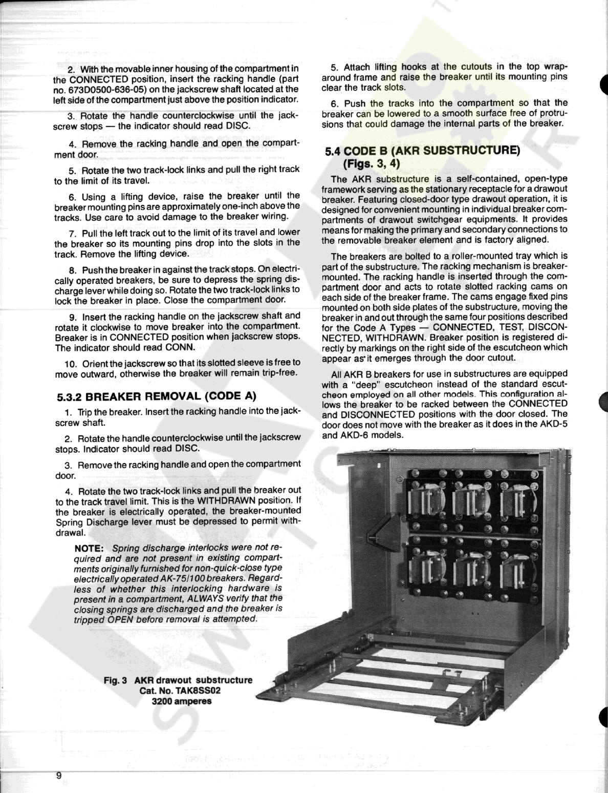
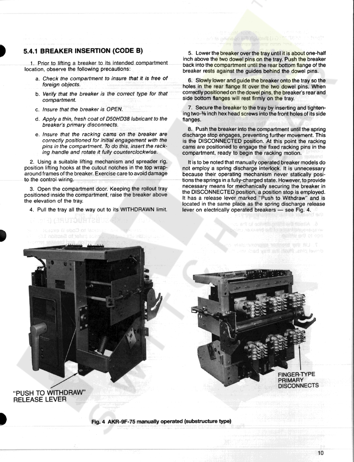
GE AKR-75 Series Programming manual

GE
GE ReliaGear Pro-Stock THQB User manual


Popular Circuit Breaker manuals by other brands


Siemens
Siemens Sentron 3VA9157-0PK1 Series operating instructions

hager
hager TS 303 User instruction

ETI
ETI EFI-4B Instructions for mounting

nader
nader NDM3EU-225 operating instructions

TERASAKI
TERASAKI NHP TemBreak PRO P160 Series installation instructions

Gladiator
Gladiator GCB150 Installation instruction