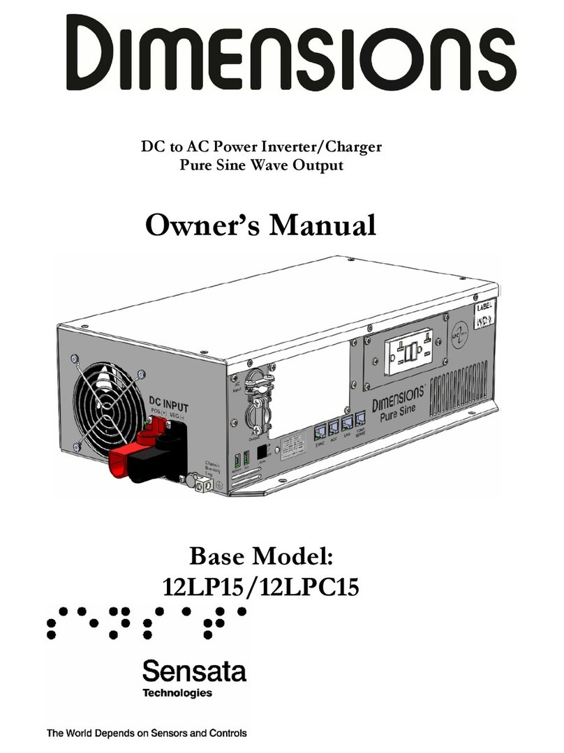
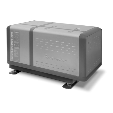
Sensata Dimensions 12LP15 User manual

DC to AC Power Inverter/Charger
Pure Sine Wave Output
Owner’s Manual
Base Model: 12LP15/12LPC15

TABLE OF CONTENTS
Introduction....................................................................................................................................................4
Contact Us ...........................................................................................................................................................................4
Important Safety Information ..........................................................................................................................................5
Specications.......................................................................................................................................................................7
Components ........................................................................................................................................................................8
Design Features...................................................................................................................................................................9
Installation .................................................................................................................................................... 10
Mount Inverter..................................................................................................................................................................10
DC Wire Gauge & Fusing...............................................................................................................................................11
AC Input/Output Connections......................................................................................................................................14
Remote Inverter “On/Off ” Switch...............................................................................................................................16
Operation ...................................................................................................................................................... 17
Inverter Power Mode .......................................................................................................................................................17
External Power Mode (LPC Only).................................................................................................................................18
GFCI...................................................................................................................................................................................23
Congurations .............................................................................................................................................. 24
Non-Volatile Memory (NVM) Setup Utility.................................................................................................................24
Default Congurations ....................................................................................................................................................25
Switch Options..................................................................................................................................................................26
Low Battery Shutdown ....................................................................................................................................................26
Sleep Mode (Load Sense) ................................................................................................................................................26
Shutdown Timer ...............................................................................................................................................................27
Auxiliary Control...............................................................................................................................................................27
Battery Options (LPC Only)...........................................................................................................................................28
Branch Circuit Rating (LPC Only).................................................................................................................................28
AC Line Qualify Time (LPC Only)................................................................................................................................28
CAN Instance and Baud Rate.........................................................................................................................................28
Troubleshooting ........................................................................................................................................... 29
LED Status Chart - Normal Operation ........................................................................................................................29
Inverter Faults and Warnings ..........................................................................................................................................30
Charger Faults and Warnings ..........................................................................................................................................32
Troubleshooting Guide....................................................................................................................................................33

TABLE OF CONTENTS CONTINUED
Appendix....................................................................................................................................................... 34
Accessories & Replacement Parts ..................................................................................................................................34
Inverter Model Options...................................................................................................................................................34
CAN....................................................................................................................................................................................35
Limited Warranty Terms & Conditions ....................................................................................................... 37

Page 4 12LPC15 Manual
INTRODUCTION
Thank you for purchasing a Dimensions™ inverter/charger from Sensata Technologies®! We think that you will
nd this product to be extremely reliable and easy to use.
Please read this manual completely before installing or operating the unit.
All information is subect to change without warning. Contact Sensata for the latest updates.
Contact Us
Sensata Technologies can be reached by phone or email if you need assistance with this product.
Phone: 1-800-553-6418 or 1-651-653-7000
Fax: 1-888-439-3565 or 1-651-653-7600
Website: http://magnum-dimensions.com/

Page 5
Introduction
12LPC Manual
Important Safety Information
Read this manual before installation. This manual contains important instructions pertaining to safety, installation,
and operation.
Save this manual and keep it in a safe place.
Sensata Technologies is an ISO 9001:2015 Registered Company.
Sensata uses the following special notices to help prevent injury and/or damage to equipment:
Safety Symbols
DANGER indicates an imminently hazardous situation which, if not avoided, will result in death or serious
injury.
WARNING indicates a potentially hazardous situation which, if not avoided, could result in death or serious
injury.
CAUTION indicates a potentially hazardous situation which, if not avoided, may result in minor or moderate
injury.
CAUTION is used without the safety alert symbol indicates a potentially hazardous situation which, if not avoided,
may result in property damage.
NOTE is used to notify of installation, operation, or maintenance information that is important but not hazard
related.
Safety Listing
Power Inverter, E100666

Page 6 12LPC15 Manual
Inverter Safety Instructions
WARNING: Power inverters produce hazardous voltages. To avoid risk of harm or re, the unit must be
properly installed.
WARNING: There are no user serviceable parts inside. Do not remove the cover.
WARNING: Power inverters should not be mounted in a location that may be exposed to rain, spray, salt, or
corrosive chemicals.
WARNING: Power inverters should not be installed in a zero-clearance enclosure.
WARNING: Damage to the power inverter will occur if correct polarity is not observed when installing the
inverter’s DC input cables.
WARNING: Damage to the power inverter will occur if an external AC power source is applied to the inverter’s
AC hardwire output.
WARNING: Power inverters contain a circuit breaker and capacitor that may produce a spark upon connection
or during normal operation. Do not mount in a conned battery or gas compartment where toxic fuel vapor is
present.
WARNING: Be sure the power inverter is turned off and AC power is disconnected when batteries are being
connected, disconnected, serviced, and replaced or personal injury and/or damage to the inverter could result.
WARNING: Working near lead-acid batteries is dangerous. There is a risk of acid exposure.
Battery Safety Instructions
WARNING: Batteries may vent explosive gases during operation.
WARNING: There is risk of high current discharge from shorting a battery that can cause re and explosion.
Use insulated tools during installation.
WARNING: Remove all rings, watches, jewelry, or other conductive items before working near the batteries.
WARNING: Inspect the batteries at least once a year for cracks, leaks, or swelling. Follow the scheduled
maintenance procedures from the battery manufacturer.
WARNING: Dispose of the batteries according to local regulations. Do not incinerate batteries; there is risk of
explosion.
WARNING: A fuse must be installed between the battery and the inverter to protect against shorted cables.

Page 7
Introduction
12LPC Manual
Specications
All ratings above assume 12.6 VDC nominal voltage, 25°C ambient temperature, and the inverter is mounted in free
air. 12.6 VDC is to be measured at the inverter input terminals.
For use at ambient temperatures less than -20°C, use the hardwire connections. The GFCI may not properly operate
at temps below -20°C.
At temperatures greater than 25°C, the inverter output is de-rated. See graph in “Operation” section of the manual.
LP units operate in inverter mode only. LPC units are able to operate in inverter mode and charge mode with
bypass.
Input Voltage (VDC) 10.5 – 15.0
DC Surge Voltage (VDC) Up to 24 VDC
Output Voltage (VAC) 120 +/- 5%
Output Frequency (Hz) 60 +/- .05%
THD < 5% at 12.6 VDC and 1500W
Output Waveform Pure Sine < 5% THD
Output Power (Watts Cont.) 1500
Output Current (AAC Cont.) 12.5
Input Current (ADC Cont.) Up to 167 at 12.6 VDC
Input Current (ADC Cont.) Up to 190 at 10.5 VDC
Peak Power (Watts) 3000
Peak Output (AAC) 25.0
Motor Starting Rating (h.p.) 1/2
Inverter Efciency Up to 80%
Charger Input Voltage (Vrms) 85 – 135 (LPC only)
Max Charger Output Current (ADC) 65 at 12.6 VDC (LPC Only)
Input Current Bypass (Arms) 20 (LPC Only)
Weight (lbs.) 30
Dimensions in. (L x W x H) 19.0” x 9.75” x 4.8” *
Operating Temperature -40°C to 50°C (-40°F to 122°F) **
Agency Listings UL458, E100666
Table 1 Specications
* Length includes DC terminals and handle.
** At ambient temperatures above 50°C, the inverter/charger may fail to restart in the event it shuts down in an
over temperature condition.

Page 8 12LPC15 Manual
Components
Figure 1 Components
A. GFCI (not available with “H” sufx)
B. Status LED
C. Local On/Off
D. AC Input and Output Breakers (no input breaker for inverter LP (inverter-only) models
E. Bonding Lug
F. DC Input Connections
G. Remote On/Off Wiring Tab
H. AUX Wiring Tab
I. AC Wiring Access Plate
J. Various Ports

Page 9
Introduction
12LPC Manual
Design Features
• GFCI: Provides 120 VAC output. Only replace with an approved GFCI.
• Status LED: This LED will show inverter operation mode and troubleshooting information. See the table in
the troubleshooting section at the rear of the manual for further operation mode descriptions.
• Local On/Off: This switch turns the inverter on or off. Switch inoperable for “HR” and “R” congurations.
• AC Input and Output Breakers: Protects the inverter from output short circuits and overloads. The 12LPC15
(inverter/charger) uses 20 A input and 15 A output breakers.
• Bonding Lug: Connects to the system ground.
• DC Input Connections: Connects to the battery bank.
• Remote On/Off Wiring Tab: Terminal is used to wire a customer supplied remote snap “On/Off ” switch.
Apply battery voltage to tab to turn on inverter.
• AUX Wiring Tab: Terminal is used to enable internal housekeeping power only. Apply battery voltage to
enable. Does not turn on inverter output.
• AC Wiring Access Plate: Provides wiring and inspection access to AC output terminals inside the AC wiring
box. To be closed during operations.
• Various Ports: “CAN” is used for connection of a CAN interface. “Temp Sense” is used for connection
a battery temperature sensor (BTS) that is sold separately. “ACC” is used for a remote switch that is sold
separately. The “Sync” port may be plugged with an empty connector because it is currently not used. The
“Temp Sense” port may also be plugged with an empty connector on LP models.
• Unit Protection: Automatic inverter short circuit/overload protection, automatic over temperature shutdown,
and AC output circuit breaker.
• Battery Protection: Automatic low battery shutdown with an in-rush delay. Other low battery settings may be
congured with the NVM Setup Utility.
• Shutdown Timer: Shutdown timer helps preserve battery life over long periods of time. When enabled, the
timer will shut the inverter off in 30 or 60 minutes regardless of load.
• Load Sense: Inverter output will shut off if no load is connected. The inverter will turn back on when it
detects that a load has been connected.
Contact the factory for updated information or for other voltage, current ratings, and battery congurations that
may be available.

Page 10 12LPC15 Manual
INSTALLATION
Mount Inverter
WARNING: Power inverters produce hazardous voltages. To avoid risk of harm or re, the unit must be
properly installed.
WARNING: Power inverters should not be mounted in a location that may be exposed to rain or spray.
WARNING: Power inverters should not be installed in a zero-clearance enclosure.
WARNING: Power inverters contain a circuit breaker and capacitor that may produce a spark upon connection
or during normal operation. Do not mount in a conned battery or gas compartment.
Installation Tools
• Wire Termination Crimper
• Cable-Ties
• Drill
• #2 Phillips Screw Driver (with a magnetic end)
• Slotted Screw Driver
• Tape Measure
• Wire Cutters
• Needle Nose Pliers
• Wire Strippers
Inverter Mounting Recommendations
NOTE: The inverter mounting location should provide adequate ventilation and clearance to maintain room
temperature during operation. At least ½” of clearance is required on all sides except the bottom.
1. Locate a suitable, secure mounting surface as close to the batteries as possible without being in the same
compartment.
2. Mount the inverter using four ¼-20 steel bolts, at and lock washers, and nuts. The length of the bolts should
be equal to the thickness of the mounting surface plus ¾”.
Figure 2 Mounting for All Models (Inches)

Page 11
Installation
12LPC15 Manual
DC Wire Gauge & Fusing
WARNING: Damage to the power inverter will occur if correct polarity is not observed when installing the
inverter’s DC input cables.
Inverter Cable
Wiring should meet all local codes and standards and be performed by qualied personnel such as a licensed
electrician.
An inverter cable kit (positive cable, negative cable, and proper fuse) is needed to connect the inverter to a battery
bank. An inverter cable kit designed to SAE guidelines can be purchased directly from Sensata – call for options.
Min. Cable and Max. Fusing Guide for 3% Voltage Drop at 100% Output
Inverter Model Full Load (ADC) Inverter to Battery Est. Cable Length in Feet
Up to 15 feet @ 25°C (77°F)
12LP15/12LPC15 190 ADC 100% Duty
(at 10.5 VDC) 1/0 AWG, 350 A Fuse
12LP15/12LPC15 190 ADC 50% Duty
(at 10.5 VDC) 1/0 AWG, 350 A Fuse
Table 2 Cable Sizing
NOTE: Using a smaller cable may cause a low battery or high temperature fault.
NOTE: 100% duty rating assumes the inverter is continuously operating at its full rated output power for at least an
hour. The 50% duty rating assumes that the inverter is operating at its full rated output power for up to 15 minutes
and then operating with a load less than 25% of its full rating for at least 15 minutes before returning to full power
and repeating. Alternatively, the inverter can also continuously operate at 50% of its rated output power. Values in
the provided table assume the inverter is operating in an ambient temperature of 25°C (77°F). For higher ambient
temperatures, additional derating may be required (i.e. may need to use a larger cable size).

Page 12 12LPC15 Manual
DC Wire Gauge & Fusing Continued
Make an Inverter Cable Kit
1. Use 1/0 AWG stranded copper cables in all cases.
NOTE: The maximum recommended length of the inverter cable is 15 ft, and the cable must be fused within 18
inches of the positive (+) terminal of the battery.
2. Use SGX cross-linked polyurethane insulation type that complies with the high temperature insulation
requirements (125°C.) of SAE J-1127 and vehicle manufacturer requirements. Reference Table 2. For 1/4” ring
lugs, use JST 38-S6.
3. Torque the DC connections on the inverter to 50-60 lbf·in.
4. Torque the inverter bonding lug to 45 lbf·in for 6 AWG or 40 lbf·in for 8 AWG.
NOTE: It is useful to use a needle nose pliers to help insert or remove the 1/4x20 screw and toothed washer.
Figure 3 Proper Installation of Cable into DC Terminal Cover

Page 13
Installation
12LPC15 Manual
DC Wire Gauge & Fusing Continued
Typical Cable Connection Procedure
NOTE: Refer to Figure 4 for a typical DC wiring diagram. See Table 2 for proper cable sizes.
1. Remove the fuse from the fuse holder.
2. Connect the inverter’s bonding lug to ground of the vehicle chassis.
3. Connect the ring terminated end of the black inverter cable set directly to the negative (-) side of the battery
bank at a negative battery post.
4. Connect the fuse holder to the positive (+) side of the battery bank.
5. Connect the ring terminated end of the red inverter cable set directly to the fuse holder.
6. Install the fuse in the fuse holder. A typical one-time spark will occur when this nal connection is made.
7. Install the fuse holder cover.
Figure 4 Typical DC Wiring Diagram

Page 14 12LPC15 Manual
AC Input/Output Connections
WARNING: Damage to the power inverter will occur if an external AC power source is applied to the inverter’s
AC hardwire output.
WARNING: Do not directly connect another source of AC power to the AC output of the inverter. This will
result in damage not covered under warranty.
GFCI
A 20 A GFCI is installed into the side of the inverter, except for hardwire-only versions (“H” sufx) where the
GFCI is omitted. The rated output of the inverter is 12.5 A. If a 20 A load is applied to the GFCI, the 15 AAC
output breaker installed on a 12LPC15 will eventually trip. The 12LPC15 allows for 20 A of bypass current. If 20
A of load is connected to the inverter or inverter/charger while in inverter mode, the inverter will shut down in
overload.
Hardwire Interface
1. Remove the cover for hardwire AC wiring.
2. Insert the AC input and output wiring through the AC output cable clamps to protect the wires from the metal
edge of the hole.
3. Connect the AC wiring to the provided internal terminal blocks. Check that the AC input wiring is connected
to the AC input terminal blocks and the AC output wiring is connected to the AC output terminal blocks. The
12LPC15 should use 14 AWG minimum for the AC output. The AC terminal block will accept 14-8 AWG wire.
4. Torque the AC terminal blocks to 10 lbf·in.
5. Connect the hot wires to the black terminal, the neutral to the white terminal, and the ground to the green
terminal.
Figure 5 Hardwire Access
Figure 6 AC Inverter Output Connections

Page 15
Installation
12LPC15 Manual
AC Input/Output Connections Continued
Figure 7 AC Input for Charger/Bypass
NOTE: The AC input should be protected by a 20 A branch rated breaker external to the inverter/charger.
NOTE: The AC output should be protected by a branch rated breaker external to the inverter if required to comply
with the National Electric Code, NFPA 70, or the Canadian Electrical Code, C22.1.
NOTE: Connecting the AC inverter input to a GFCI protected outlet may cause some interference with the
inverter’s GFCI.

Page 16 12LPC15 Manual
Remote Inverter “On/Off ” Switch
Remote Inverter “On/Off ” Switch Installation – Customer Supplied
For non “-R” sufx versions, a momentary switch must be used. In non-remote only mode, the momentary switch
will toggle the inverter state between on and off, or standby and off while in charge mode. The remote switch may
be customer supplied or ordered separately from the factory.
For remote only “-R” sufx versions, a snap switch must be used. If a snap switch is used in place of a momentary
switch, the inverter may not correctly respond. In remote-only mode, the snap switch will turn the inverter on and
off when in inverter mode. When in charger mode, it will switch the inverter state between off and standby.
1. Mount the remote switch in a convenient location.
2. Using 18 AWG wire and an insulated ¼” female faston, wire between the “Remote On/Off ” connection on the
left side of the inverter.
3. Wire from the remaining connection on the remote switch to the battery positive (+) terminal.
4. Install a 5 A in-line fuse in series within 18 inches from the positive (+) terminal of the battery.
Figure 8 12LPC15R with Snap Switch

Page 17
Operation
12LPC15 Manual
OPERATION
Once the inverter has been fully installed, wired, and DC power has been applied, the inverter is ready to turn on.
The status LED beneath the AC wiring box on the left side of the inverter shows the current state of the inverter.
Inverter Power Mode
Usage: Any 120 VAC, 60 Hz single phase product within the inverter’s power rating.
The inverter can be turned on by using the local or remote switch. When the inverter is on, the local status LED
will be a constant green. When the local “On/Off ” switch is enabled in assemblies without the “R” sufx, any
switch may turn the inverter on or off. When using the local switch, a momentary remote switch must be used. With
the remote-only inverter, only the remote snap switch will turn on the inverter. The local “On/Off ” switch will be
inactive. The function of the switch will depend on the mode of the unit and if the AUX tab is enabled and being
used.
The inverter front status LED will be green while the inverter is on. The AC power produced by the inverter comes
from the energy stored in the battery bank through an electronic inversion process. A transformer, a Metal Oxide
Silicon Field Effect Transistors (MOSFET), a lter capacitor, and a microprocessor are used to generate clean AC
power.
The inverter will operate at DC input voltages ranging from 10.5 VDC to 16 VDC. If the inverter’s input voltage
exceeds 16 VDC, the inverter may stop operating. The inverter can tolerate up to 24 VDC for 5 minutes; over 5
minutes will cause a shut down. Input voltages above 24 VDC will result in an immediate shutdown. The inverter
will restart when the input voltage drops below 16 VDC. When the input voltage drops to the low battery voltage,
the inverter will stop operating. When the lead-acid battery bank voltage drops to 10.5 volts, the battery is fully
discharged.
The inverter output needs to be de-rated as the ambient temperature surrounding it increases. See Figure 9 for
operation at 12.6 VDC.
Figure 9 Inverter Output Temp Derating

Page 18 12LPC15 Manual
External Power Mode (LPC Only)
Battery Charger
The LED display panel will show charger mode and the status LED located on the side of the inverter will blink
green to indicate the charging process mode. See the LED Status Chart for additional blink codes.
NOTE: The battery charger requires about 8 VDC to be present at the DC output before the charger will operate.
The battery charger will engage automatically and independently of the inverter on/off status. The three-step
charging process modes are bulk, accept, and oat.
Bulk
The charger will output the maximum rated current to the battery until the battery voltage (as measured at the
charger DC terminals) reaches the maximum voltage threshold or the constant current timer expires.
Accept
The charger will output at the rated voltage until the output current reaches nearly zero or the constant voltage time
expires.
Float
The charger will output current and voltage at the minimum duty cycle until the voltage drops below a threshold.

Page 19
Operation
12LPC15 Manual
External Power Mode (LPC Only) Continued
Battery Charger Continued
Battery Type AGM GEL Wet
Bulk Charge Phase
Bulk
Bulk charge current limit SEE SPEC
Bulk phase terminates 1. When battery voltage reaches the accept voltage
Accept Charge Phase
Accept
Accept charge voltage @ 77°F/25°C 14.3 VDC 13.7 VDC 14.6 VDC
Accept voltage temp compensated 5mv/cell/°C
Maximum accept voltage at low temps 15.0 VDC @ 4°C 14.5 VDC @ -6°C 15.0 VDC @ 10°C
Accept phase terminates 1. When charge current is reduced.
2. When the accept timeout is reached.
Accept phase timeout 6 hours (may be congured through CAN)
Float Charge Phase
Float
Float voltage @77°F/25°C 13.4 VDC 13.4 VDC 13.2 VDC
Float voltage temp comp 5mv/cell/°C
Condition (Equalization) Phase
Condition
Condition voltage @ 77°F/25°C N/A N/A 15.5 VDC
Condition voltage temp compensation N/A N/A 30.24mV/cell/°C
Condition duration N/A N/A 4 hours
Condition frequency N/A N/A Manual Control
Battery Temperature
Battery Temp
Charger Warm Battery: output switches to compensated oat from
bulk/accept/off (hot)
>122F/50°C
<140F/60°C
Charger High Battery Temp: output to off >140F/60°C
Charger resumes in previous mode: bulk/accept/oat <112F/45°C
Table 3 Three-Step Charger Recipe with BTS Reference

Page 20 12LPC15 Manual
External Power Mode (LPC Only) Continued
Charger Battery Temperature Sensor (BTS)
The BTS measures the battery temperature and automatically adjusts the charger output voltage for the fastest and
safest charge.
NOTE: If the BTS cable is not connected, the battery charger will not function. The charger will output
about 8 VDC if the battery voltage has been removed after the charger starts.
When batteries are cold, their chemical reaction is slowed so they will not charge as easily. A charge voltage
optimized for room temperature will not charge the battery at low temperatures. The BTS cable allows the charger
to increase the charge voltage for optimum charging at low temperatures.
When batteries are hot, their chemical reaction is accelerated and they absorb energy too quickly. A charge voltage
optimized for room temperature will tend to overcharge the batteries and cause gassing. The BTS will cause the
charger to decrease the charge voltage to a safe level.
The charger will switch to a “warm battery” mode in which the charger will only provide a oat voltage when the
batteries reaches 122°F/50°C to 140°F/60°C. If the battery temperature continues to rise over 140°F/60°C, the
charger will shut off. The charger will resume charging in the “warm battery” mode when the battery cools to
131°F/55°C. The charger will resume normal charging when the battery cools to 113°F/45°C.
Install the Battery Temperature Sensor
1. Connect the lug end of the temperature compensation cable to the negative post of the battery.
2. Insert the sensor plug to the appropriate mating connector located at the side of the inverter labeled “Temp
Sense.” BTS cable is part# ME-BTS-XX (XX=length in feet - 6, 8, 15, 25, 40).
Figure 10 BTS
Other manuals for Dimensions 12LP15
1
This manual suits for next models
1
Table of contents
Other Sensata Inverter manuals

Sensata
Sensata Magnum Energy CSW3012-X User manual
Sensata
Sensata Magnum-Dimensions MagnaSine MS-G Series User manual
Sensata
Sensata 24TX60 User manual
Sensata
Sensata Dimensions 12LPC15 User manual
Sensata
Sensata Magnum Energy MS Series User manual
Sensata
Sensata ADI-300/3000D User manual

Sensata
Sensata dimensions 12NP18 User manual
Sensata
Sensata SSI-12HF3.5N User manual
Sensata
Sensata 12/800N User manual
Sensata
Sensata Dimensions 24NP36 User manual

