Sense Innoband SC00 User manual

Version 0.1
Innoband SC00
Innoband Sense Commander
(Z-Wave / Ethernet Wireless Gateway)
User Man al

Version 0.1
User Manual
Innoband SC00
Information in this document is subject to change without notice and does not represent a commitment on the
part of Innoband Technologies, Inc. The software described in this document is furnished under a license
agreement and may be used or copied only in accordance with the terms of the license agreement. It is against
the law to copy the software on any other medium except as specifically allowed in the license agreement. The
licensee may make one copy of the software for backup purposes. No part of this manual may be reproduced or
transmitted in any form or by any means, electronic or mechanical, including photocopying and recording, for any
purpose without the written permission of Innoband Technologies, Inc.
All contents are Copyright © 2013 Innoband, Inc. All rights reserved.
Manual Version 0.1
January 2013
Innoband is a trademark of Innoband Technologies, Inc. The trademarks, logos and service marks (“Marks”)
displayed on this manual are the property of Innoband or other third parties. Users are not permitted to use these
Marks without the prior written consent of Innoband or such third party that may own the Mark. IBM is a
registered trademark of International Business Machines Corporation. Intel and Pentium are registered
trademarks of Intel Corporation. Microsoft, MS-DOS, Windows, and the Windows logo are registered trademarks
of Microsoft Corporation. All other products are trademarks or registered trademarks of their respective owners.

Table Content
Getting started...................................................................................................... 4
Unpacking.......................................................................................................... 4
Overview ........................................................................................................... 4
Specifications ..................................................................................................... 4
Physical Outlook ................................................................................................. 5
About -WaveTM ................................................................................................. 5
LED Descriptions (TBD) ....................................................................................... 6
Install your new device .......................................................................................... 7
Install the Hardware ........................................................................................... 7
Create User Account at Sense Cloud...................................................................... 7
Log Into Sense Commander ................................................................................. 8
Log Into Sense Cloud Server ...............................................................................11
Perform -WaveTM Device Inclusion......................................................................12
Perform -WaveTM Device Exclusion .....................................................................14
Using Sense Commander.......................................................................................15
PC Browser App .................................................................................................15
Run and Edit Scenes ..........................................................................................16
Define and Configure Triggers .............................................................................19
Android App ......................................................................................................21
Troubleshooting ...................................................................................................22
Certifications........................................................................................................23
FCC..................................................................................................................23
Warning ...........................................................................................................23
Warranty .............................................................................................................25
Contact information ..............................................................................................27

4
Getting started
Unpacking
Check the contents of the package against the pack contents checklist below. If any of the
items is missing, then contact the dealer from whom the equipment was purchased.
•Main Sense Commander Unit
•Mounting Screws (2x)
•Quick Start Guide
•AD/DC Power Adapter
•Ethernet Cable
Overview
Innoband's -Wave Sense Commander gateway connects to an Ethernet router to allow
users to control a -Wave based sensor network.
The sensor network may include -Wave security devices such as door/window sensors,
motion detectors, sirens, and door locks. The network may also includes home automation
and energy monitoring devices such as appliance on/off switches, light socket on/off
adapters, light dimmers, thermostats, and irrigation controller.
This Sense Commander is designed to control the -Wave devices when it's properly
connected to an Ethernet network. This Ethernet network can be a LAN (local area network)
or WAN (wide area network). Users can then access the WSN Controller through LAN or
WAN using web browsers on PCs, Mac's, tablets, or mobile devices such as smart phones.
Specifications
Model Name Innoband Sense Commander
Model No SC00
Part No 250-I-SC00-00
Power Adapter 12V DC/1A
Operating Frequency 908.42 MHz
Battery Type (Optional) AAA x 4
Operating Range Up to 30 meters line of sight (indoor)

5
Physical O tlook
Abo t Z-WaveTM
-WaveTM is a wireless communications protocol designed to remotely control applications in
residential and commercial environments.
Each -WaveTM network is identified by a Network ID, and each device is further identified
by a Node ID. A device must be "included" to the -WaveTM network before it can be
controlled via -WaveTM.
This ‘Inclusion” process (also known as "pairing" and "adding") is achieved by pressing a
sequence of buttons on the controller and the device being added to the network. This
sequence only needs to be performed once, after which the device is always recognized by
the controller. Devices can be removed from the -WaveTM network by a similar “Exclusion”
process of button strokes.
Summary:
F nction Description
Inclusion Add a -Wave device (e.g. Dimmer) to -Wave network
Exclusion Remove a -Wave device (e.g. Dimmer) from -Wave network
Reset Restore Sense Commander to factory default
1Inclusion Button 5USB Ports (reserved)
2Exclusion Button 6Ethernet Network Jack
3LED Indicators (x4) 7DC Power Jack
4Recessed Reset Button
Front View Top View Rear View
2
1
3
4
5
6
7

6
LED Descriptions (TBD)
The table below provides a summary of LED functions. Please refer to applicable user’s
guides on applicable -WaveTM devices for inclusion and exclusion procedures.
F nction Description LED & Siren Stat s
Power Indicate if the unit is properly
powered
LED: solid green
Ethernet Indicate if the unit is connected
to an Ethernet network
LED: blinking green
1. Configure the -Wave
Controller into inclusion mode.
2. Press the Inclusion button until
In/exclusion LED start to blink
in red.
3. The blinking LED stops if a -
Wave sensor is discovered and
paired with the Commander.
Inclusion
4. The inclusion mode times out
in 30 seconds if nothing is
discovered.
LED: blinking red
1. Configure the -Wave
Controller into exclusion mode.
2. Press the Exclusion button until
In/exclusion LED start to blink
in red.
3. The blinking LED stops if a -
Wave sensor is discovered and
excluded with the Commander.
Exclusion
4. The exclusion mode times out
in 30 seconds if nothing is
discovered.
LED: blinking red
-Wave Indicate if -Wave communication
is working properly.
LED: n/a

7
Install yo r new device
Innoband’s SC00 Sense Commander gateway is designed for dry indoor environment only.
Please follow these steps below to properly set up the unit.
Install the Hardware
1. Unpack Sense Commander from the package.
2. Use the supplied Ethernet cable and connect the Commander’s Network port to an
available port on the home network’s Ethernet Router.
3. Power on the Sense Commander using the supplied power adapter.
4. Wait about 60 seconds until the flashing red In/Exclusion LED goes off, and the
Power LED is solid green, while the Ethernet LED blinks in green steadily.
Create User Acco nt at Sense Clo d
1. If applicable, turn on a computer that is wire or wirelessly connected to the same
Ethernet router.
2. Launch a web browser (such as Internet Explorer, Google Chrome, Apple Safari,
FireFox) on the computer.
3. In the URL field, enter www.innobandsense.net.
4. On the Sign In page, select Create new account.
5. Follow the screen instructions, enter the desired email address, password, and
validation code and click ‘Authorize’.
6. An automated email will be sent to the email address entered earlier.
7. Retrieve the email (check your SPAM folder if necessary) and click on the validation
link in the email message.

8
Log Into Sense Commander
1. If applicable, turn on a computer that is wire or wirelessly connected to the same
Ethernet router.
2. Download the gateway discovery utility application at:
http://www.innobandsense.com/images/SenseDiscovery.rar or
http://www.innobandsense.com/images/SenseDiscovery.zip.
3. Open the downloaded file, run Setup.exe to install the application on the computer.
4. Upon completion, look for the “DiscoverUtility” program shortcut on the computer’s
desktop.
5. Launch the application by double clicking the desktop shortcut.
6. Click on the “Scan” button.
7. An IP address will be shown under “Gateway IP”. Make a note of the Gateway IP
address shown in the “Gateway List”.
8. Double click on the Gateway IP address.
9. A browser session will automatically be launched. (Alternatively, launch a web

9
browser (such as Internet Explorer, Google Chrome, Apple Safari, FireFox) on the
computer. In the URL field, enter the Gateway IP address found using the utility
above.)
10. When prompted, enter ‘admin’ as the User Name and leave the Password field blank,
and click on ‘Log In”.
11. You’re now accessing the web server inside the Commander’s flash memory.
12. Select “Configuration Devices”.
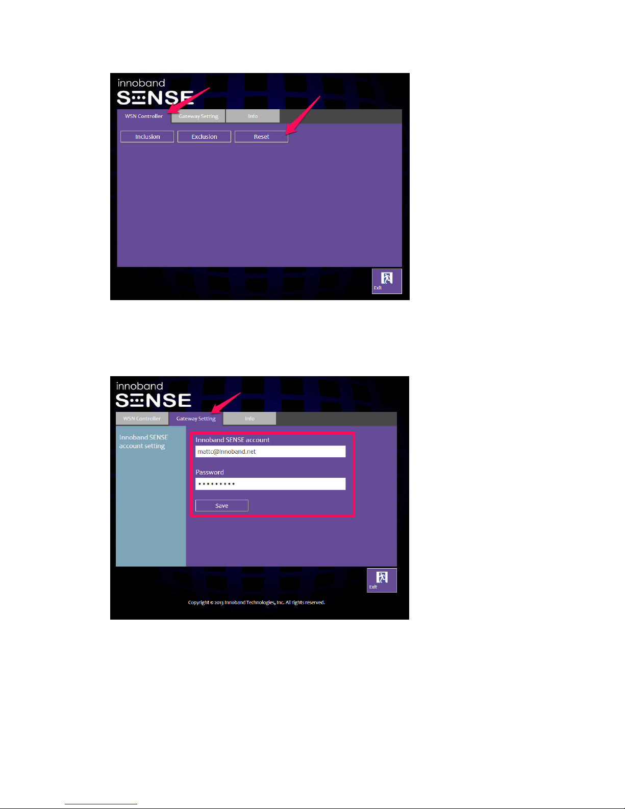
13. Select “WSN Controller”.
14. Select “Gateway Setting”.
10
15. Click the “Reset” button and proceed with resetting the gateway. Wait until it’s
completed.
16. Click on the “Gateway Setting” tab.
17. Replace the default account and password with the New Account created earlier at
www.innobandsense.net. Click ‘Save’, and then ‘Exit’.
18. Go back to the Device / System Setup, and click the WSN Controller tab.
19. Click ‘Log off’.

11
Log Into Sense Clo d Server
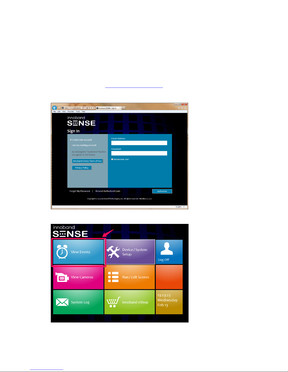
1. Launch a new browser session on the computer.
2. In the URL field, enter www.innobandsense.net.
3. On the Sign in page, select ‘Use existing account’ and enter the new account’s
information, click ‘Log in’.
4. If a green “Found New Gateway Version” banner is displayed on the upper right of
the screen, a newer firmware is available for download and installed on Sense
Commander.

12
5. Click on the green “Found New Gateway Version” banner. Click ‘Yes’ to proceed and
upgrade the gateway firmware.
6. Look for the count down on the screen to complete.
7. At the completion of the count down, your Sense Commander gateway will be up to
date. Click on ‘Back to Home’ to return to the main menu.
8. If text message notification is desired, configure the mobile phone number
associated with the user account by clicking ‘Device / System Setup’. Click on the
‘User’ tab. Click on the ‘Cell Phone Number’ button to configure mobile phone
number associated with the account.
Perform Z-WaveTM Device Incl sion
1. Install the batteries into the -Wave device, or connect it to a wall outlet.
2. Make sure the -Wave device to be paired with the Sense Commander is no more
than 3 feet from the Commander. (The -Wave device can be moved to its
permanent location after the ‘inclusion’ pairing procedure with the gateway is
completed.)
3. Refer to the user’s guide on the -Wave device and look for the programming /
inclusion / tamper switch on the -Wave device.
4. When the -Wave device is ready (programming / inclusion / tamper switch is found),
13
press and hold the Inclusion button (item #1 on page 5) on the Commander until the
In/Exclusion LED start blinking in red. This allows the Commander to enter into
“inclusion mode” for 30 seconds.
5. Secondly, on the -Wave device, configure the device into ‘inclusion mode’ by
pressing and releasing the programming / inclusion / tamper switch quickly 3
consecutive times.
6. If the device is successfully paired with the Commander, the In/Exclusion LED will
stop blinking in red.
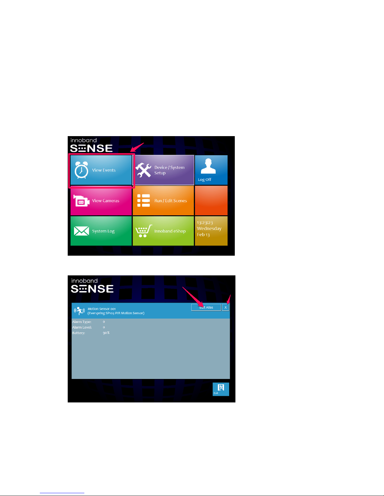
7. Return to the main menu, and click on ‘View Events’, the newly added device will be
shown.
8. To rename the device to give it a more meaningful name (i.e. Lobby Motion Sensor),
click on the ‘Edit Alias’ button. When completed, click on the ‘X’ to exit.
9. If necessary, repeat Step 2~8 above to include additional -Wave devices.
10. If inclusion attempt failed, please perform the exclusion procedure in the following
section. Then, repeat Step 2~8 above again to include the -Wave device.

14
Perform Z-WaveTM Device Excl sion
1. Install the batteries into the -Wave device, or connect it to a wall outlet.
2. Make sure the -Wave device to be paired with the Sense Commander is no more
than 3 feet from the Commander. (The -Wave device can be moved to its
permanent location after the ‘inclusion’ pairing procedure with the gateway is
completed.)
3. Refer to the user’s guide on the -Wave device and look for the programming /
inclusion / tamper switch on the -Wave device.
4. When the -Wave device is ready (programming / inclusion / tamper switch is found),
press and hold the Exclusion button (item #2 on page 5) on the Commander until
the In/Exclusion LED start blinking in red. This allows the Commander to enter into
“exclusion mode” for 30 seconds.
5. Secondly, on the -Wave device, configure the device into ‘exclusion mode’ by
pressing and releasing the programming / inclusion / tamper switch quickly 3
consecutive times.
6. If the device is successfully excluded with the Commander, the In/Exclusion LED will
stop blinking in red.
7. If necessary, repeat Step 2~5 above to exclude additional -Wave devices.
15
Using Sense Commander
PC Browser App
1. Launch a new browser session on a computer.
2. In the URL field, enter www.innobandsense.net.
3. On the Sign in page, select ‘Use existing account’ and enter the account’s
information, click ‘Log in’.
4. On the main menu, select “View Events”. This is where an all-at-a-glance view on
the -Wave devices included or paired with the Commander is available.
5. To perform device control on applicable devices, click on the device icon, then click
on the control tool (i.e. on/off button or the dimmer slider) to make adjustments.

16
When finished, click on ‘X’ to return to the ‘View Events’ page.
6. When the sensor status changes (i.e. door is opened, motion sensor detects
movement), the devices shown in the ‘View Events’ page will be shown in red.
R n and Edit Scenes
1. Scene is a series of sensor device actions for a desired task or home ambience. For
example, you can have a scene for “Movie Night” where a push of a button on the
app could dim all the lights connected to dimmers. A scene for “Arriving Home” could
open the garage door, turn on the hall lights and disarm the security system. -
Wave scenes are powerful tools for home control because they let simple user
actions control complex events.

17
2. To program a scene, log into www.innobandsense.net and click on ‘Run / Edit Scene’
on the main menu.
3. Click on ‘Add Scene’ button on the lower left.
4. Input the desired name in the ‘Scene Name’ text box. Click on the ‘Add Command’
to add the first sensor action.
5. Select from the available list of devices. (Note: Only sensor devices such as
dimmers, on/off plugs that can carry out actions will be available on the list.

18
‘Passive’ sensor devices such as motion sensor or window sensor will not be shown
on the list.)
6. Once a device is selected, a list of available commands will be shown. Select the
desired command for the sensor device from the list of commands.
7. Once the command is selected, the available value will be shown. The image below
shows a dimmer is to be set at level 48.
8. Click Add to complete the configuration.
9. Click ‘Add Command’ to add another device action. Repeat step 5~8 above to
complete the configuration.
10. Click ‘Save’ to save the settings.
11. To execute the series of sensor commands that were just defined, click the
button.
12. To edit and make changes to the scene, click on the to proceed with changes.

19
Define and Config re Triggers
1. There are times where a series of commands need to be carried out when a certain
‘condition’ is met. For example, the siren should sound when a door is opened, or
when movement is detected by the motion sensor. These conditions can be defined
under the ‘Trigger’ tab.
2. To define a specific condition, click on the Trigger tab.
3. Click ‘Add Trigger’.

20
4. Input the desired name in the ‘Trigger Name’ text box.
5. Select the desired notification method under the Notify dropdown box.
6. Click on the ‘Add Command’ to add the first triggering condition.
7. Under the ‘When’ section, select the desired device, the desired command, and value.
8. Under the ‘Do’ (actions to be performed) section, select either 1) ‘Scene’ to execute
a series of actions associated a pre-defined scene, or 2) ‘Device’ to execute an action
from an available sensor device.
Table of contents
Other Sense Gateway manuals

Popular Gateway manuals by other brands

Linear Access
Linear Access AP-4 installation instructions

KZTech
KZTech iSurf 1000 User's operation manual

Belden
Belden GRASS VALLEY IPG-3901 Guide to installation and operation

Moxa Technologies
Moxa Technologies Mgate MB3660 Quick installation guide

More
More NetComm CF40 Wi-Fi 6 quick start guide

Billion
Billion BiGuard 50G quick start guide


