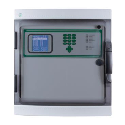
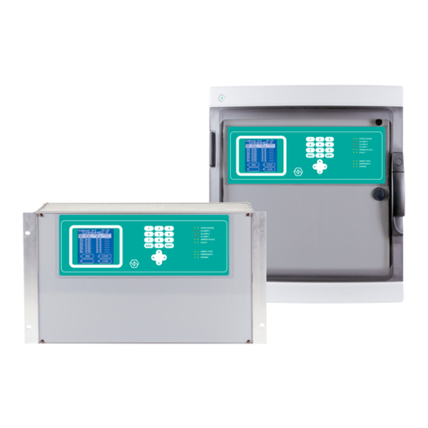
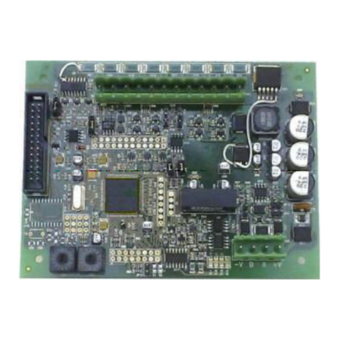
Sensitron STG/OUT16-S2 User manual

Manuale d’istruzione / Instruction Manual
MT4983 R1 24/11/2021
©2021 SENSITRON S.R.L. - All rights reserved - www. sensitron.it
Modulo uscite /
Output module
STG/OUT16-S2

THIS MANUAL MUST BE CAREFULLY READ BY ALL PERSONS WHO HAVE OR
WILL HAVE THE RESPONSIBILITY FOR INSTALLING, USING OR SERVICING
THIS PRODUCT.
Like any equipment, this product will perform as designed only if installed,
used and serviced in accordance with the manufacturer’s instructions.
OTHERWISE, IT COULD FAIL TO PERFORM AS DESIGNED AND PERSONS
WHO RELY ON THIS PRODUCT FOR THEIR SAFETY COULD SUFFER SEVERE
PERSONAL INJURY OR DEATH.
The warranties made by Sensitron s.r.l. with respect to this product are
voided if the product is not installed, used and serviced in accordance with
the instructions in this user guide. Please protect yourself and others by
following them.
We recommend our customers to write or call us regarding this equipment
prior to use or for any additional information relative to use or repair.
QUESTO MANUALE DEVE ESSERE LETTO ATTENTAMENTE DATUTTI COLORO
CHE HANNO O AVRANNO LA RESPONSABILITA’ DI INSTALLARE, UTILIZZARE
O DI PRESTARE UN SERVIZIO DI ASSISTENZA SU QUESTO PRODOTTO.
Come ogni componente di un sistema, questo prodotto funzionerà corret-
tamente solo se installato, utilizzato e controllato come prescritto dal fab-
bricante.
IN CASO CONTRARIO, POTREBBE NON FUNZIONARE CORRETTAMENTE E LE
PERSONE CHE AFFIDANO LA LORO SICUREZZA A QUESTO PRODOTTO PO-
TREBBERO SUBIRE DANNI PERSONALI O LETALI.
La garanzia riconosciuta da Sensitron s.r.l. su questo prodotto potrebbe
essere nulla se il prodotto non venisse installato, utilizzato e controllato
secondo le istruzioni fornite con il presente manuale. Per favore, protegge-
tevi seguendole attentamente.
Invitiamo i nostri clienti a scriverci o a chiamarci per ogni informazione ri-
guardo questo strumento, il suo uso o una sua eventuale riparazione.

ItalianoEnglish
SUMMARY
1. Introduction..................................................................................................... 5
2. Module layout................................................................................................. 5
3. Addressing ....................................................................................................... 5
4. STG/8REL relay board (optional) .............................................................. 7
5. Module dimensions ...................................................................................... 8
6. Instructions for disposal.............................................................................. 8
SOMMARIO
1. Introduzione.................................................................................................... 1
2. Topograco modulo ..................................................................................... 1
3. Indirizzamento................................................................................................ 1
4. Scheda relè STG/8REL (opzionale)........................................................... 3
5. Dimensioni modulo...................................................................................... 4
6. Istruzioni per lo smaltimento .................................................................... 4

ITALIANO
Pag. 1
1. Introduzione
I moduli remoti STG/OUT16-S2 vengono montati in campo e collegati ai loop RS485 della
centrale Multiscan++S2. Forniscono 16 uscite Open Collector (commutazione a negativo)
con funzione programmabile per l’attivazione remota di sirene, elettrovalvole, relè ecc.
A ciascun modulo STG/OUT16-S2 possono venir collegate no a 2 schede a 8 relè (opzionali)
che trasformano l’uscita da Open Collector a contatto di scambio libero da tensione. Ciascun
modulo deve essere indirizzato tramite appositi commutatori rotativi. L’indirizzo deve essere
univoco e compreso tra 1 e 255. Per il corretto uso e settaggio dei moduli, vi invitiamo a far
riferimento al manuale tecnico della centrale.
2. Topograco modulo
Figura 1) Topograco STG/IN8S
3. Indirizzamento
L’indirizzamento dei moduli STG/OUT16-S2 si esegue tramite i due commutatori rotativi in
esadecimale RSW 1 e 2. I commutatori rotativi permettono una congurazione esadecima-
le (base 16). Ogni commutatore ha 16 posizioni (0-F) ed il puntatore viene posizionato sul
numero scelto tramite un cacciavite, a formare un valore decimale da 1 a 255 (vedi tabella).
Per il numero massimo di moduli che è possibile collegare, far riferimento al manuale tecnico
della centrale.
Ogni modulo deve avere un indirizzo univoco nel sistema. Non sono ammessi indirizzi doppi,
anche se i moduli sono su linee seriali (Bus) diverse.
Commutatori rotativi per
l’indirizzo del modulo
Morsettiera uscite O/C
Collegamento scheda relè (opzionale)
Esempio di collegamento relè
-V +V
Outputs 9-16
-V
Out 1-8
+V
+
+
v
v
C
C
O
O
M
M
N
N
O
O
R
R
L
L
2
2
N
N
C
C
+
+
v
v
C
C
O
O
M
M
N
N
O
O
R
R
L
L
2
2
N
N
C
C
+V
+V
Resistenza di fine linea
Se il modulo è l’ultimo della
linea, chiudere JP10
Morsettiera alimentazione (-V/+V)
Linea seriale RS485 (B/A)
LED
DL1: Guasto WD
DL2: TX Data
DL3: RX Data
DL4: RTS
DL5: Power ON
SD1-1 Settaggio velocità comunicazione:
ON: 115.000 bps
OFF: 9600 bps

ITALIANO
Pag. 2
Figura 2) Esempio: Se i due commutatori sono posizionati come sopra, RSW2 su 0 ed RSW1 su D, l’indirizzo corrispondente in decimale è 13 (vedi
tabella sottostante)
Tabella 1) Conversione da decimale ad esadecimale. (*) Indirizzi non disponibili con protocollo Modbus, (**)Indirizzo non disponibile con proto-
collo Galileo.
DEC HEX DEC HEX DEC HEX DEC HEX DEC HEX DEC HEX DEC HEX
1 01 38 26 75 4B 112 70 149 95 186 BA 223 DF
2 02 39 27 76 4C 113 71 150 96 187 BB 224 E0
3 03 40 28 77 4D 114 72 151 97 188 BC 225 E1
4 04 41 29 78 4E 115 73 152 98 189 BD 226 E2
5 05 42 2A 79 4F 116 74 153 99 190 BE 227 E3
6 06 43 2B 80 50 117 75 154 9A 191 BF 228 E4
7 07 44 2C 81 51 118 76 155 9B 192 C0 229 E5
8 08 45 2D 82 52 119 77 156 9C 193 C1 230 E6
9 09 46 2E 83 53 120 78 157 9D 194 C2 231 E7
10 0A 47 2F 84 54 121 79 158 9E 195 C3 232 E8
11 0B 48 30 85 55 122 7A 159 9F 196 C4 233 E9
12 0C 49 31 86 56 123 7B 160 A0 197 C5 234 EA
13 0D 50 32 87 57 124 7C 161 A1 198 C6 235 EB
14 0E 51 33 88 58 125 7D 162 A2 199 C7 236 EC
15 0F 52 34 89 59 126 7E 163 A3 200 C8 237 ED
16 10 53 35 90 5A 127 7F 164 A4 201 C9 238 EE
17 11 54 36 91 5B 128 80 165 A5 202 CA 239 EF
18 12 55 37 92 5C 129 81 166 A6 203 CB 240 F0
19 13 56 38 93 5D 130 82 167 A7 204 CC 241 F1
20 14 57 39 94 5E 131 83 168 A8 205 CD 242 F2
21 15 58 3A 95 5F 132 84 169 A9 206 CE 243 F3
22 16 59 3B 96 60 133 85 170 AA 207 CF 244 F4
23 17 60 3C 97 61 134 86 171 AB 208 D0 245 F5
24 18 61 3D 98 62 135 87 172 AC 209 D1 246 F6
25 19 62 3E 99 63 136 88 173 AD 210 D2 247 F7
26 1A 63 3F 100 64 137 89 174 AE 211 D3 248 (*) F8
27 1B 64 40 101 65 138 8A 175 AF 212 D4 249 (*) F9
28 1C 65 41 102 66 139 8B 176 B0 213 D5 250 (*) FA
29 1D 66 42 103 67 140 8C 177 B1 214 D6 251 (*) FB
30 1E 67 43 104 68 141 8D 178 B2 215 D7 252 (*) FC

ITALIANO
Pag. 3
DEC HEX DEC HEX DEC HEX DEC HEX DEC HEX DEC HEX DEC HEX
31 1F 68 44 105 69 142 8E 179 B3 216 D8 253 (*) FD
32 20 69 45 106 6A 143 8F 180 B4 217 D9 254 (*) FE
33 21 70 46 107 6B 144 90 181 B5 218 DA 255 (**) FF
34 22 71 47 108 6C 145 91 182 B6 219 DB
35 23 72 48 109 6D 146 92 183 B7 220 DC
36 24 73 49 110 6E 147 93 184 B8 221 DD
37 25 74 4A 111 6F 148 94 185 B9 222 DE
4. Scheda relè STG/8REL (opzionale)
La scheda espansione opzionale 8 relè STG/8REL converte in contatti di scambio liberi da
tensione le uscite O/C del modulo di uscita STG/OUT16-S2. A ciascun modulo di uscita
possono essere collegate no a due schede relè. Una scheda relè viene collegata diretta-
mente al modulo di uscita (connettore J1) ed una seconda scheda relè viene collegata alla
prima.
NC C NO
Modulo STG/OUT16-S2 Out 2 Out 3 Out 4
Out 1 Out 9 Out 10 Out 11 Out 12
Out 8 Out 7 Out 6 Out 5 Out 16 Out 13
Out 15 Out 14
1 2 3 4 5 6 7 8 9 10 11 12 13 14 15 16
Uscite O/C
NC C NO
NO C NC NO C NC
Figura 3) Collegamento scheda relè
Nel caso in cui non vengano collegate le schede STG/8REL, è neccesario chiudere i pin 4 e 6
del connetore J1 della scheda STG/OUT16. Di default sono già chiusi.
ATTENZIONE!

ITALIANO
Pag. 4
Sensitron ha una politica di continuo sviluppo e miglioramento dei suoi prodotti. Pertanto, le speciche del
dispositivo descritte in questo documento possono essere modicate senza preavviso. In caso di modica del
prodotto, Sensitron declina ogni responsabilità. I dati possono cambiare, così come la legislazione e si consiglia
vivamente di ottenere copie delle più recenti normative, standard e linee guida emesse. Questa pubblicazione
non intende costituire la base di un contratto. Nessuna parte di questa pubblicazione può essere riprodotta,
distribuita o trasmessa in qualsiasi forma o con qualsiasi mezzo, inclusi fotocopie, registrazioni o altri metodi
elettronici o meccanici, senza la previa autorizzazione scritta di Sensitron.
5. Dimensioni modulo
Figura 4) Dimensione modulo
6. Istruzioni per lo smaltimento
Quando il dispositivo raggiunge la ne della sua vita utile, deve essere smaltito in conformi-
tà con i requisiti locali di gestione dei riuti e la legislazione ambientale.
I materiali utilizzati si possono dividere nelle seguenti categorie:
³Scatola del terminale remoto: Plastica
³Base board: Riuti di apparecchiature elettriche e elettroniche (RAEE)
In alternativa, il vecchio dispositivo può essere imballato in modo sicuro, chiaramente con-
trassegnato per lo smaltimento ambientale e restituito a Sensitron.
125,00 mm
107,00 mm
105,00 mm
75,00 mm

ENGLISH
Pag. 5
1. Introduction
The STG/OUT16-S2 remote modules are eld mounted and connected via RS485 buses to
the control panel Multiscan++S2. They provide 16 Open Collector outputs (negative switch)
with programmable functions to remotely trigger Sirens, Solenoid valves, Relays, etc.
Each STG/OUT16-S module can be connected to up to 2 boards and 8 relays (optional) that
convert the Open Collector output to a powerless exchange contact.
Each module must be addressed using the rotary switches placed on the PCB. The address
must be univocal and between 1 and 255.
Please refer to the control panel manual for the appropriate module using and setting.
2. Module layout
Figure 1) Layout STG/IN8S
3. Addressing
The STG/OUT16-S2 modules are addressed using the two rotary switches in RSW 1 and 2
hexadecimals. Rotary switches permit hexadecimal settings (base 16). Each switch as 16
positions (0-F) and the pointer is positioned on the number chosen using a screwdriver to
create a decimal value between 1 and 255 (see table). For the maximum number of modules
that can be connected to the unit refer to the control panel manual.
O/C output connections
-V +V
Outputs 9-16
Relay board connection (optional)
-V
Out 1-8
+V
+
+
v
v
C
C
O
O
M
M
N
N
O
O
R
R
L
L
2
2
N
N
C
C
+
+
v
v
C
C
O
O
M
M
N
N
O
O
R
R
L
L
2
2
N
N
C
C
+V
+V
Example of relay connection
DL1: WD Fault
DL2: TX Data
DL3: RX Data
DL4: RTS
DL5: Power ON
EOL resistor
If the module is the last of the
bus line, close JP10
Power supply (-V/+V)
RS485 serial line (B/A)
SD1-1 Communication Baud Rate setting:
ON: 115.000 bps
OFF: 9.600 bps
Rotary switches for
the module address
LED

ENGLISH
Pag. 6
Each module must have univocal address in the system. Dual addresses are not permitted
even if modules are on dierent serial buses.
Figure 2) Example: If the address switches are set in this manner, RSW2 at 0 and RSW1 at D, the corresponding address in decimal number
would be 13 (see table below).
Table 1) Conversion from decimal to hexadecimal numbers (*) unavailable addresses for the Modbus protocol, (**) unavailable address for the
Galileo protocol
DEC HEX DEC HEX DEC HEX DEC HEX DEC HEX DEC HEX DEC HEX
1 01 38 26 75 4B 112 70 149 95 186 BA 223 DF
2 02 39 27 76 4C 113 71 150 96 187 BB 224 E0
3 03 40 28 77 4D 114 72 151 97 188 BC 225 E1
4 04 41 29 78 4E 115 73 152 98 189 BD 226 E2
5 05 42 2A 79 4F 116 74 153 99 190 BE 227 E3
6 06 43 2B 80 50 117 75 154 9A 191 BF 228 E4
7 07 44 2C 81 51 118 76 155 9B 192 C0 229 E5
8 08 45 2D 82 52 119 77 156 9C 193 C1 230 E6
9 09 46 2E 83 53 120 78 157 9D 194 C2 231 E7
10 0A 47 2F 84 54 121 79 158 9E 195 C3 232 E8
11 0B 48 30 85 55 122 7A 159 9F 196 C4 233 E9
12 0C 49 31 86 56 123 7B 160 A0 197 C5 234 EA
13 0D 50 32 87 57 124 7C 161 A1 198 C6 235 EB
14 0E 51 33 88 58 125 7D 162 A2 199 C7 236 EC
15 0F 52 34 89 59 126 7E 163 A3 200 C8 237 ED
16 10 53 35 90 5A 127 7F 164 A4 201 C9 238 EE
17 11 54 36 91 5B 128 80 165 A5 202 CA 239 EF
18 12 55 37 92 5C 129 81 166 A6 203 CB 240 F0
19 13 56 38 93 5D 130 82 167 A7 204 CC 241 F1
20 14 57 39 94 5E 131 83 168 A8 205 CD 242 F2
21 15 58 3A 95 5F 132 84 169 A9 206 CE 243 F3
22 16 59 3B 96 60 133 85 170 AA 207 CF 244 F4
23 17 60 3C 97 61 134 86 171 AB 208 D0 245 F5
24 18 61 3D 98 62 135 87 172 AC 209 D1 246 F6
25 19 62 3E 99 63 136 88 173 AD 210 D2 247 F7
26 1A 63 3F 100 64 137 89 174 AE 211 D3 248 (*) F8

ENGLISH
Pag. 7
DEC HEX DEC HEX DEC HEX DEC HEX DEC HEX DEC HEX DEC HEX
27 1B 64 40 101 65 138 8A 175 AF 212 D4 249 (*) F9
28 1C 65 41 102 66 139 8B 176 B0 213 D5 250 (*) FA
29 1D 66 42 103 67 140 8C 177 B1 214 D6 251 (*) FB
30 1E 67 43 104 68 141 8D 178 B2 215 D7 252 (*) FC
31 1F 68 44 105 69 142 8E 179 B3 216 D8 253 (*) FD
32 20 69 45 106 6A 143 8F 180 B4 217 D9 254 (*) FE
33 21 70 46 107 6B 144 90 181 B5 218 DA 255 (**) FF
34 22 71 47 108 6C 145 91 182 B6 219 DB
35 23 72 48 109 6D 146 92 183 B7 220 DC
36 24 73 49 110 6E 147 93 184 B8 221 DD
37 25 74 4A 111 6F 148 94 185 B9 222 DE
4. STG/8REL relay board (optional)
The STG/8REL 8-relay optional expansion board converts STG/OUT16 O/C outputs into
voltage free changeover contact. Up to two relay boards can be connected to each output
module. A relay board is directly connected to the output module (J1 connector) and a
second relay board is connected to the rst.
Figure 3) Relay board connection
If the STG/8REL boards are not connected, it is necessary to close pins 4 and 6 of the J1 con-
nector of the STG/OUT16 board. By default they are already closed.
NC C NO
Out 2 Out 3 Out 4
Out 1 Out 9 Out 10 Out 11 Out 12
Out 8 Out 7 Out 6 Out 5 Out 16 Out 13
Out 15 Out 14
1 2 3 4 5 6 7 8 9 10 11 12 13 14 15 16
NC C NO
NO C NC NO C NC
STG/OUT16-S2 Module
Open Collector outputs
WARNING!

Contact details: SENSITRON s.r.l. Viale della Repubblica, 48 - 20007 - Cornaredo (MI) Italy
LEADER IN SIL2 (SIL3) FIXED GAS DETECTION SYSTEMS
Sensitron has a policy of continuous development and improvement of its products. As such the specica-
tion for the device outlined in this document may be changed without notice. In case of modication of the
product, Sensitron disclaims all liability. Data may change, as well as legislation and you are strongly advised to
obtain copies of the most recently issued regulations, standards and guidelines. This publication is not inten-
ded to form the basis of a contract. No part of this publication may be reproduced, distributed, or transmitted
in any form or by any means, including photocopying, recording, or other electronic or mechanical methods,
without the prior written permission of Sensitron.
5. Module dimensions
Figure 4) Module dimensions
6. Instructions for disposal
When the device reaches the end of its life, it should be disposed of in accordance with local
waste management requirements and environmental legislation.
Employed materials are subdivided into the following categories:
³Remote terminal unit enclosure: Plastic
³Base board: Waste Electrical & Electronic Equipment (WEEE)
Alternatively, the old device may be securely packaged, clearly marked for environmental
disposal and returned to Sensitron.
125,00 mm
107,00 mm
105,00 mm
75,00 mm
Table of contents
Languages:
Other Sensitron Control Unit manuals
Popular Control Unit manuals by other brands
Communication Devices
Communication Devices PCM620 user manual
Panasonic
Panasonic PAN1326C Design guide
Telecom
Telecom Octopus F50 operating instructions
LOVATO ELECTRIC
LOVATO ELECTRIC EXP10 30 instruction manual
Nordson EFD
Nordson EFD 752V Series Maintenance & Parts Guide

KSB
KSB TRIODIS 150 operating instructions
