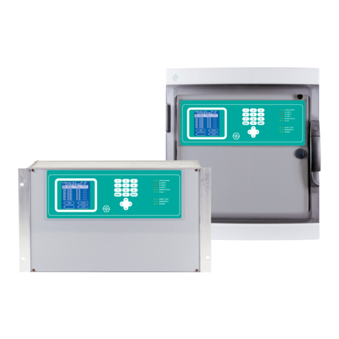
Sensitron MULTISCAN++S1 Guide

MT3401E.doc rev.0 21/05/13 Pagina 1 di 86
MULTISCAN++S1
ATEX and SIL 1 certified
(64-128-256)
INSTALLATION AND USE
MANUAL
SENSITRON S.r.l. Viale della Repubblica, 48
20010 CORNAREDO MI - Italy
Tel: + 39 02 93548155 Fax: + 39 02 93548089

Technical Manual MULTISCAN++S1
MT3401E.doc rev.0 21/05/13 Pagina 2 di 86
Warning
THIS MANUAL MUST BE CAREFULLY READ BY ALL PERSONS WHO HAVE OR
WILL HAVE THE RESPONSIBILITY FOR INSTALLING, USING OR SERVICING THIS
PRODUCT.
Like any equipment, this product will perform as designed only if installed, used and
serviced in accordance with the manufacturer’s instructions. OTHERWISE, IT COULD
FAIL TO PERFORM AS DESIGNED AND PERSONS WHO RELY ON THIS PRODUCT
FOR THEIR SAFETY COULD SUFFER SEVERE PERSONAL INJURY OR DEATH.
The warranties made by Sensitron s.r.l. with respect to this product are voided if the
product is not installed, used and serviced in accordance with the instructions in this
user guide. Please protect yourself and others by following them.
We recommend our customers to write or call regarding this equipment prior to use or
for any additional information relative to use or repair.

Technical Manual MULTISCAN++S1
MT3401E.doc rev.0 21/05/13 Pagina 3 di 86
INDEX
1) INTRODUCTION................................................................................................................................... 5
1.1) SYSTEM CONFIGURATION.................................................................................................................. 6
1.2) TECHNICAL SPECIFICATIONS.............................................................................................................. 6
2) INSTALLATION.................................................................................................................................... 7
2.1) MOUNTING AND ELECTRICAL CONNECTIONS....................................................................................... 7
2.1.1) DIAGRAM AND PART IDENTIFICATION........................................................................................... 8
2.1.2) LAYOUT SCHEDA CENTRALE....................................................................................................... 9
2.1.3) POWER SUPPLY CONNECTIONS ................................................................................................ 10
2.1.4) DIP SWITCH SETTING FOR THE RS485 BUSS,PC COMMUNICATION AND CONTROL PANEL LANGUAGE
10
2.2) FIELD DEVICE CONNECTIONS........................................................................................................... 11
2.2.1) DETECTORS CONNECTION ....................................................................................................... 12
2.3) STG/IN8-S REMOTE INPUT MODULE................................................................................................ 17
2.1) STG/OUT16-S REMOTE OUTPUT MODULE ...................................................................................... 18
2.1.1) STG/8REL RELAY EXPANSION BOARD ..................................................................................... 19
2.1.2) STG/IN8-S AND STG/OUT16-S MODULE ADDRESSING............................................................ 19
2.1.3) DETECTOR IDENTIFICATION...................................................................................................... 21
2.2) PROGRAMMING BY PC.................................................................................................................... 21
3) SYSTEM POWER UP AND OPERATION.......................................................................................... 22
3.1) POWER ON.................................................................................................................................... 23
3.2) SYSTEM STATES AND OPERATION.................................................................................................... 24
3.2.1) SYSTEM STATES...................................................................................................................... 24
3.3) USER LEVELS................................................................................................................................. 28
3.3.1) OPERATOR LEVEL.............................................................................................................. 29
3.3.2) MAINTENANCE LEVEL.......................................................................................................... 30
3.3.3) ENGINEER LEVEL ................................................................................................................. 30
3.4) MENU DETAILS........................................................................................................................... 30
3.5) 1- MENU....................................................................................................................................... 30
3.5.1) ACTIVE EVENTS.................................................................................................................. 31
3.5.2) EVENT LOG.......................................................................................................................... 33
3.5.3) PRINT................................................................................................................................... 35
3.5.4) SYSTEM INFO...................................................................................................................... 36
3.6) 2-LOGOUT................................................................................................................................... 37
3.7) 4-LOGIN....................................................................................................................................... 37
3.8) 3-SYSTEM ................................................................................................................................... 38
3.8.1) ZONES.................................................................................................................................... 38
3.8.2) MODULES ............................................................................................................................... 40
3.8.3) RELAY OUTPUTS ..................................................................................................................... 40
3.8.4) DETECTORS (CHANNELS)........................................................................................................ 42
4) PC CONFIGURATION SOFTWARE .................................................................................................. 45
4.1) INTRODUCTION............................................................................................................................... 45
4.1.1) MINIMUN PC HARDWARE REQUIREMENTS .................................................................... 45
4.2) INSTALLATION................................................................................................................................. 45
4.3) LAUNCHING THE PROGRAM ............................................................................................................. 45
4.3.1) CONTROL PANEL SELECTION.................................................................................................... 46
4.3.2) PROGRAM HOMEPAGE............................................................................................................. 48
4.4) PROGRAM MENU............................................................................................................................. 48
4.4.1) FILE........................................................................................................................................ 49
4.4.2) SETTINGS............................................................................................................................... 53
4.4.3) USERS.................................................................................................................................... 53
4.4.4) COMMUNICATION .................................................................................................................... 57
4.4.5) REPORT ................................................................................................................................. 61
4.4.6) INFO....................................................................................................................................... 62

MT3401E.doc rev.0 21/05/13 Pagina 4 di 86
4.5) MODIFICATION OR CREATION OF A NEW CONFIGURATION FILE............................................................ 63
4.5.1) SYSTEM INFORMATION............................................................................................................. 63
4.5.2) GENERAL SETTINGS ................................................................................................................ 64
4.5.3) ZONES.................................................................................................................................... 65
4.5.5) CHANNELS.............................................................................................................................. 68
4.5.6) RELAY OUTPUS....................................................................................................................... 75

MT3401E.doc rev.0 21/05/13 Pagina 5 di 86
1) INTRODUCTION
The MULTISCAN++S1 is a gas detection control unit designed to meet the widest range of
flexibility required by the market.
The control panel is based on a powerful microprocessor which provides a wide range of self-
diagnostic procedures to detect and locate possible faults.
Extremely flexible and reliable, it can manage up to 64 or 128 or 256 gas detectors (according
to the different 4 versions). The detectors can be either of addressable type, directly connected
on buses, or 4-20mA analogical types connected via 8-input STG/IN8-S remote modules.
System architecture also includes 8 on-board machine relays and the potential to expand
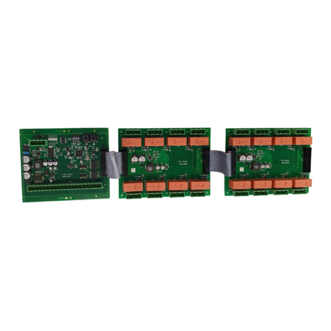
outputs up to 256 using remote STG/OUT16-S modules and 8-relay boards. Up to 4 serial
buses can be connected to the unit.
The unit allows for three alarm thresholds to be set for each detector. The alarm threshold
activation mode changes according to the type of gas detection profile and connected detector
The unit is inserted in a plastic box complete with 27 Vdc 4 A power supply.
Summary table of the devices that can be connected to the various MULTISCAN++S1 unit
versions.
Panel type
Number of
serial bus
Detectors
max
number
Outputs
max number
ST.G/IN8-S
Max number
ST.G/OUT16
Max number
Notes
Multiscan++S1 64
4 open o 2
closed
64+8(*)
128+8(*)
8
8
Multiscan++S1 128
4 open or 2
closed
128+8(*)
256+8(*)
16
16
Multiscan++S1 256
4 open or 2
closed
256+8(*)
256+8(*)
32
16
(*) channels enclosed in the panel
Other MULTISCAN++S1 panel features:
Event log can be displayed on the screen or downloaded to a PC.
RS232 serial port for PC connection for programming and control via specific software.
Parallel port for printer connection.

MT3401E.doc rev.0 21/05/13 Pagina 6 di 86
1.1) System configuration
BUS 1
BUS 2
(1)
(4)
(3)
(2)
(5)
(6)
(1) (4)
(1) RILEVATORI GAS ANALOGICI 4-20 mA / 4-20 mA ANALOG GAS DETECTORS
(2) MODULO 8 INGRESSI ANALOGICI ST.G/IN8-S / ANALOG 8 INPUT MODULE
ST.G/IN8-S
(3) CAVO2 FILI TWISTATI PER Rs485 + 2 FILI PER ALIMENTAZIONE (12-24 Vdc) /
2 TWISTED WIRES FOR THE Rs485 BUS + 2 WIRES FOR THE POWER SUPPLY (12-24 Vdc)
(4) RILEVATORI GAS CON USCITASERIALE Rs485 / GAS DETECTORS WITH Rs485 OUTPUTS
(5) MODULO 16 USCITE O/C ST.G/OUT16-S / 16 O/C OUTPUTS MODULE ST.G/OUT16-S
(6) MODULO 8 RELE’ ST.G/8REL / 8 RELE’ ST.G/8REL MODULE
16 O/C
BUS 3
BUS 4
MULTISCAN ++ S1 CONTROL PANEL
E’ possibile realizzare il sistema con
4 BUS aperti oppure 2 BUS chiusi
It is possible to make the system with
4 oper BUS or 2 closed BUS
Fig. 1.1) System block diagram
1.2) Technical specifications
Technical specifications
Housing:
Plasticbox IP65 dim.L.470, H.426, D.148 mm.
Inputs:
Max. 256 detectors with RS485 communications connected on the bus or 4-20 mA via
STG/IN8 S modules
Outputs:
8 relays on the unit + 64 (or 128 or 256) Open Collector outputs on STG/OUT16-S modules
(optional STG/8REL relay board)
Unit relay contact and
optional ST.G/8REL board
capacity
16 A at 250 Vac
Serial ports:
4 x RS485 (2 for vers. 64)
1 x RS232 (PC connection)
Network connection
Optional TCP/IP module
Power:
100-120 Vac or 200-240 Vac selectable on the power supply via switch
Absorption:
Max 10 VA
Warm-up time:
Settable from 2 to 10 min. (default 3 min.)
Display:
Liquid crystal display (LCD)
Optic indications:
Double row of 9 leds
Working temp.
0/-55°C
Storage temp.
-20 ÷ +60 C°
Working RH:
15-85% (non condensed)
Storage RH
5-85% (non condensed)

MT3401E.doc rev.0 21/05/13 Pagina 7 di 86
2) INSTALLATION
2.1) Mounting and electrical connections
After opening the transparent unit door, also open the front panel by rotating the black lock to
UNLOCK.
Disconnect the two wires that lead from the unit board (JP47 and JP51 connectors) to the
bottom of the box for power connections (see fig. 2.1.1). Close the front panel turning the lock to
LOCK.
Remove the 4 screws at the 4 corners of the box and remove the front part of the unit box.
Holes can now be drilled in the back of the box for wire passage.
We recommend you use an IP65 wire clamp at wire entrance to maintain the same protection
level as the unit.
Secure the back of the unit to the wall using the holes (D) or by the enclosed brakets.
Fig. 2.1 a) Control panel box
Dimensions (mm): A 470, B 426, C 380, D 312, E 128, F 148, G 14, H 125, I 75, L 50, M 48, N
98, O 41
Connect the tri-polar mains wire to the power supply terminal board (minimum 1.5mm2
per pole) and secure it with the specific wire clamp.
Power the unit and, next, connect the red and black tipped faston wires to the 2 12 V 7
Ah max lead buffer battery power supply, housing them in the lower part of the cabinet
(bottom)

MT3401E.doc rev.0 21/05/13 Pagina 8 di 86
Vac
Power Supply
+-
BATTERIES
Fig. 2.1 b) Power supply
2.1.1) Diagram and part identification
Box version
1
2
3
8
4
5
6
7
7
1- Power Supply (27 Vdc 4A)
2- 2 x 12V 7Ah batteries (not included)
3- RS232 serial port (PC connection)
4- Parallel port (printer connection)
5- Relay outputs (8)
6- 8 detectors 4-20 mA inputs
7- Bus RS485 bus connections
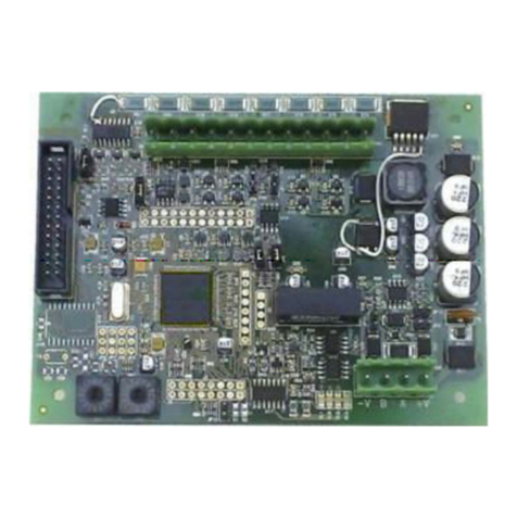
8- Panel main board
Fig. 2.1.1) Unit diagram and part identification

MT3401E.doc rev.0 21/05/13 Pagina 9 di 86
2.1.2) Layout scheda centrale
Linea Rs485 1 / Rs485 Serial Line 1
Linea Rs485 2 / Rs485 Serial Line 2
Linea Rs485 3 /Rs485 Serial Line 3
Linea Rs485 4 / Rs485 Serial Line 4
Scheda Linea seriale 1
Serial Line 1 card
Scheda linea seriale 2
Serial line 2 card
Scheda linea seriale 3
Serial line 3 card
Scheda linea seriale 4
Serial line 4
CPU
Ingressi analogici 4-20 mA/ 4-20 mA analog inputs
8
7
6
5
4
3
2
1
Porta parallela stampante
Parallel printer port Porta seriale PC
PC serial port
Uscite relè
Relay outputs
Ingressi digitali
(not used)
Digital inputs
(not used)
Segnali di controllo dall’alimentatore
Control signals from power supply
Alimentazione +/- dall’alimentatore
+/- from Power Supply
+-
+-
Uscite ausiliarie di alimentazione 1 A cad.
Auxiliary power supply outputs 1 A each
Slot scheda SD
SD card slot
D3 switches: Control panel language
Language
English
Italian
Spanish
Portoguese
Sw4 Sw3 Sw2 Sw1
ON OFF OFF OFF
OFF
OFF
OFF OFF
ON ON ON
ON ON ON
ONON
Dip switch settaggio (vedi tabella)
Setting switches (see table)
Fusibile 3 A / 3A Fuse
1
2
3
4
5
6
7
8
Non usato / Not used
Fig. 2.1.2) Layout scheda centrale

MT3401E.doc rev.0 21/05/13 Pagina 10 di 86
2.1.3) Power supply connections
27,6 Vdc/ 4 A power supply
+
-
100-120 Vac
200-240 Vac
Earth
110 220
select the
input voltage
110/220V is selected by switch
Before power ON please check
Input voltage avoiding damage
Selezionare 110/220V con
lo switch all’interno. Verificare
prima di dare alimentazione,
per evitare danneggiamenti.
Scheda centrale
Control panel main board
Fig. 2.1.3) Main board power supply connection
2.1.4) DIP switch setting for the RS485 buss, PC communication and control
panel language
The series of SD2 dip-switches must be set for:
Communication (baud rate and protocol) for unit compatibility with various gas
detector versions and IN / OUT modules.
Communication (baud rate) of the RS232 serial port for the communication with
the PC
The SD3 dip switch series is for set the language text of the control panel display.
Note: the dip switch state is acquired at the control panel switch ON
D3 switches: Control panel language
Language
English
Italian
Spanish
Portoguese
Sw4 Sw3 Sw2 Sw1
ON OFF OFF OFF
OFF
OFF
OFF OFF
ON ON ON
ON ON ON
ONON
Dip switch settaggio (vedi tabella)
Setting switches (see table)
Non usato / Not used
Fig. 2.1.4) Dip-switch SD2 and SD3

MT3401E.doc rev.0 21/05/13 Pagina 11 di 86
Dip-switch 1: Baud Rate Bus RS485
Positione
Velocità comunicazione bus
Detector and Module compatibility
ON
115.200
Smart “S” gas detectors and ST.G/IN8-S /
ST.G/OUT16-S modules
OFF
9.600
Smart “3G” gas detectors and ST.G/IN8-S /
ST.G/OUT16-S modules
Dip-switches 2 and 3: RS485 bus communications protocol
Sw 2
Sw 3
Protocollo
Compatibilità Rilevatori e
Moduli
Note
ON
ON
Galileo
Smart “S” gas detectors and
ST.G/IN8-S / ST.G/OUT16-S
modules
Baud Rate 115.200
OFF
ON
IDI
OldSMARTIDI,SMART3CCand
CDdetectors.Old STG/IN8and
STG/OUT16modules.STG/IN8-N
and STG/OUT-16-Nmodules
Baud rate 9600
ON
OFF
Modbus
SMART3G gas detectors;
STG/IN8-S and STG/OUT16-S
modules
Baud rate 9600
(if SMART3G detectors are
not connected to the bus,
115.200 Bps can be set
(switch 1))
OFF
OFF
Configurazione non usata
Dip-switch 4 and 5: Communication (baud rate) of the RS232 serial port for the
communication with the PC
Sw 4
Sw 5
Baud Rate
ON
ON
9600 Bit/sec.
OFF
ON
19200 Bit/sec.
ON
OFF
38400 Bit/sec.
OFF
OFF
115200 Bit/sec. (default)
Dip-switches 6 and 7: not used
Dip-switch 8: restore default settings
Position
Function
ON
When turned on, restores unit default settings
OFF
Normal position
2.2) Field device connections
The unit has 4 RS485 data buse connected to field gas detectors. The 4 serial buses can be
used in "open" mode (4 bus) or "closed" (2 bus). The choice is set during programming with the
PC software.
Via serial bus the gas detectors are connected (directly on the bus if detectors with RS485
feature model or via the 8-input STG/IN8.S modules if 4-20 mA type) and ST.G/OUT16-S output
modules.
The length of each serial data bus is maximum 1000 mt.

MT3401E.doc rev.0 21/05/13 Pagina 12 di 86
4 conductors are required for device connections (meaning both Smart P detectors and IN and
OUT modules): 2 for the RS485 serial bus and two for device power. For this reason, two
different wires must be used or a single wire that has suitable characteristics, described below.
-) The RS485 serial bus must be connected with an EIA RS 485 connection wire: No. 2
conductors with 0.22/0.35 mm2section + shield (TWISTED PAIR). Nominal capacity between
conductors < 50 pF/m, nominal impedance 120 ohm. Total line length with this type of
connection must not exceed 1.000 meters. An example of a recommended wire is a BELDEN
9841 or similar wire (EIA RS485 data transmission wire). Only connect detectors (and IN and
OUT modules) in cascade. Avoid tree or delta connection since they reduce interference
immunity.
-) Detector power supply (and IN and OUT modules on the bus) must be connected with a 2-
core wire with adequate section based on the number of connected devices, their distance from
the power supply and each device’s consumption (please see the technical manual enclosed
with gas detectors for this purpose).
The different Multiscan++S1 unit versions can support a different number of detectors from 64
to 256.
Each device connected on the unit's RS485 bus must have its own univocal address. STG/IN8
S and STG/OUT16-S module address settings are described later in this manual. See the
manual of the detector for its address settings.
Note: for the MTS++S1 256 version, the maximum number of connectible points on a single bus
is 128.
2.2.1) Detectors connection
Gas detectors can be connected to the MULTISCAN++S1 control panel in two different
ways, based on the detector output signal.
1) 4-20 mA analogue proportional output.
The detector connected to the unit and ST.G/IN8 S modules will send a 4-20 mA signal
referring to its range (i.e. 0-300 ppm, 0-30 ppm, 0-100% LEL etc.) and the unit, suitably
programmed, will display the relevant gas concentration indication measured by the
detector and consequently activate the alarms when the set values are reached.
2) RS485 digital proportional output
The detector connected to the unit will send a data signal on the RS485 line. This signal
is referring to its range (i.e. 0-300 ppm, 0-300 ppm, etc.) and the unit, suitably
programmed, will display the relevant gas concentration indication measured by the
detector and consequently activate the alarms when the set values are reached.

MT3401E.doc rev.0 21/05/13 Pagina 13 di 86
Detectors with 4-20mA output
Detectors with 4-20mA analog output are connected to the unit via remote 8-input modules
STG/IN8-S. The modules are connected on the panel's bus to be field mounted far from the
control panel.
A 4-20mA transmitter requires a 3-core wire for connections: 2 wires for power supply (usually
12 to 28 Vdc but refer to the gas detector technical manual) and one wire for the 4-20mA signal.
A 3x0.75mm2shielded wire is recommended since it can cover a 100 m distance between the
gas detector and STG/IN8-S input module.
Detectors with 4-20 mA output directly connected to the unit
Scheda centrale / panel main board
Det.1
Det.2
Det.3
Det.4
Det.5
Det.6
Det.7
Det.8
S
Fig. 2.2.1 a) Connection of the 8 detectors of the control panel
Rilevatori con uscita 4-20 mA collegati a moduli ST.G/IN8-S
The following diagram illustrates connections between a 4-20mA gas detector and a STG/IN8 S
input module. When starting the system, make sure minimum 12Vdc voltage reaches each gas
detector.
-V
I8
I7
I6
I5
+V
-V
I4
I3
I2
I1
+V
-V
B
A
+V
REMOTE INPUT
MODULE ST/G.IN8
(+V) (-V)
(S)
Positive
Negative
4-20 mA
signal
4-20 mA
analog
gas
detector
Rilevatore
analogico
4-20 mA
MODULO INGR.
4-20 mA ST/G.IN8
Fig. 2.2.1 b) Connection of the 8 detectors of the ST.G/IN8-S module

MT3401E.doc rev.0 21/05/13 Pagina 14 di 86
Detectors with RS485 output
Detectors with RS485 digital outputs are directly connected to the RS485 bus.
4 wires are required in this type of connection: 2 for the RS485 serial bus and 2 for
device power supply. For this reason we suggest you use two different wires or a single
wire with suitable features as described below.
-) The RS485 serial bus must be connected with an EIA RS 485 connection wire: No. 2
wires with 0.22/0.35 mm2section with shield (TWISTED PAIR). Nominal capacity
between conductors < 50 pF/m, nominal impedance 120 ohm. Total line length with this
type of connection must not exceed 1,000 metres. An example of a recommended cable
is a BELDEN 9841 or similar wire (EIA RS485 data transmission wire). Only connect
detectors (and IN and OUT modules) in cascade. Avoid tree or star connections since
they reduce interference immunity.
-) The power supply to the detectors (and IN and OUT modules on the bus) must be
connected with a 2-core wire with adequate section based on the number of
connected devices, their distance from the power supply and each device’s
consumption (please see the technical manual enclosed with gas detectors for this
purpose).
Note: each detector connected on the RS485 line must have its own univocal address between
1 and 255 (247 for the ModBus protocol). Please see the gas detector technical manual for
address settings.
The following diagram illustrates the connection on the bus of gas detectors and remote
IN/8 or OUT/16 modules to the control panel.

MT3401E.doc rev.0 21/05/13 Pagina 15 di 86
Scheda centrale / panel main board
+ - AB
+ - AB
+ - AB
+ - AB
+ - A B
+-
+-
+-
+-+-
+-
+
-
A
B
Dalla centrale o dall’alimentatore ausiliario remoto
From the control panel or from the remote auxiliary power supply
Cavo twistato / schermato 2x022 (Belden 9841 o equivalente)
Twisted / shielded 2x0,2 cable (Belden 9841 or equivalent)
Loop1
Loop2
Loop3
Loop4
Al rilevatore o modulo
successivo
To the next detector
or module Come Loop 1
As Loop 1
Fig. 2.2.1 c) RS485 bus devices connection (Open bus)

MT3401E.doc rev.0 21/05/13 Pagina 16 di 86
Scheda centrale / panel main board
+ - AB
+ - AB
+ - AB
+ - AB
+ - A B
+-
+-
+-
+-+-
+-
+
-
Dalla centrale o dall’alimentatore ausiliario remoto
From the control panel or from the remote auxiliary power supply
Cavo twistato / schermato 2x022 (Belden 9841 o equivalente)
Twisted / shielded 2x0,2 cable (Belden 9841 or equivalent)
Bus1
Bus3
Bus4
Come Bus 1-2
As Bus 1-2
B
B
A
A
Bus2
Fig. 2.2.1 d) RS485 bus devices connection (Closed bus)

MT3401E.doc rev.0 21/05/13 Pagina 17 di 86
2.3) STG/IN8-S remote input module
STG/IN8-S remote modules are field mounted and are connected to the panel via
RS485 buses. They are used to connect 8 x 4-20mA analog gas detectors. Each
module must be addressed using the rotary switches on the PCB. The address must be
univocal and between 1 and 255. For the maximum number of modules, see the table at
chapter. 1- Introduction
Jumper da non manomettere
/ jumpers not to be touched
Jp1
Jp2
Jp3
Jp4
Jp9
Jp11
Jp12
Jp14
Closed 1-2
Closed
Closed
Open Open
Open
Closed 1-2
Led
DL1: Guasto WD /WD Faul
DL2: TX Data
DL3: RX Data
DL4: RTS
Jp10 Resistenza di file linea
(EOL resistor)
Se il modulo è l’ultimo della linea chiudere Jp10
/ If the module is the last of the bus line, close JP10
A
B
Rs485 serial line
Morsettiera alimentazione e linea seriale
(Power supply and serial line)
Jp13 Communication Baud Rate setting:
Closed 115.000 bps (Multiscan++ control panel
Open 9.600 bps (old Galileo Multiscan control panel)
Jp13 Settaggio velocità comunicazione:
Chiuso 115.000 bps (Centrale Multiscan ++)
Aperto 9.600 bps (vecchia centrale Galileo Multiscan)
Commutatori rotativi
per l’indirizzo del modulo
Channels 5-8 Channels 1-4
-V +V-V +V
Morsettiera rilevatori
(gas detector connections)
Open
Rotary switches for
the module address)
Fig. 2.3) ST.G/IN8-S module

MT3401E.doc rev.0 21/05/13 Pagina 18 di 86
2.1) STG/OUT16-S remote output module
STG/OUT16-S remote modules are field mounted and connected to the panel via RS485 buses.
They provide 16 Open Collector outputs (negative switch) with programmable functions to
remotely trigger Sirens, Solenoid valves, Relays, etc. Each STG/OUT16-S module can be
connected to up to 2 boards of 8 relays that convert the Open Collector output to a powerless
exchange contact.
Each module must be addressed using the rotary switches placed on the PCB. The address
must be univocal and between 1 and 255 (1-247 for the Modbus protocol).
For the maximum number of modules, see the table at chapter. 1- Introduction
Morsettiera alimentazione
e linea seriale
(Power supply and serial line)
Commutatori rotativi per
l’indirizzo del modulo
Jp13 Communication Baud Rate setting:
Closed 115.000 bps
(Multiscan++ control panel
Open 9.600 bps
(old Galileo Multiscan control panel)
Jp13 Settaggio velocità comunicazione:
Chiuso 115.000 bps
(Centrale Multiscan ++)
Aperto 9.600 bps
(vecchia centrale Galileo Multiscan)
Led
DL1: Guasto WD /WD Faul
DL2: TX Data
DL3: RX Data
DL4: RTS
Resistenza di file linea
(EOL resistor)
chiudere s
close i
è l’ultimo della linea /
f the module
is the last of the bus line
e il modulo
-V +V -V
Morsettiera uscite O/Ci
(O/C output connections)
Outputs 9-16 Out 1-8
A
B
Rs485 serial line
Collegamento scheda relè (opzionale)
/ Relay board connection (optional)
Jumper da non manomettere
/ jumpers not to be touched
Jp5
Jp6
Jp7
Jp8
Jp9
Jp11
Jp12
Closed 1-2
Closed
Closed
Open
Open
Open
Open
Rotary switches
for the module address
+V
+V
+V
Esempio di collegamento relè
Example of relay connection
Fig. 2.4) STG/OUT16-S module

MT3401E.doc rev.0 21/05/13 Pagina 19 di 86
2.1.1) STG/8REL relay expansion board
The STG/8REL 8-relay expansion board converts STG/OUT16-S O/C outputs into voltage free
changeover contact. Up to two relay boards can be connected to each output module. A relay
board is directly connected to the output module (J1 connector) and a second relay board is
connected to the first.
Esempiocollegamento
/ Connectionexample
Fig. 2.4.1) Relay board connection to the output module
2.1.2) STG/IN8-S and STG/OUT16-S module addressing
STG/IN8-S and STG/OUT16-S modules are addressed using the two rotary switches in
RSW 1 and 2 hexadecimals. Rotary switches permit hexadecimal settings (base 16).
Each switch as 16 positions (0-F) and the pointer is positioned on the number chosen
using a screwdriver to create a decimal value between 1 and 255 (see table 1).
For the maximum number of modules, see the table at chapter. 1- Introduction.
Each module must have univocal address in the system. Dual addresses are not
permitted even if modules are on different serial buses.

MT3401E.doc rev.0 21/05/13 Pagina 20 di 86
Example:
Se i due commutatori sono posizionati come sopra, RSW2 su 0 ed RSW1 su D, l’indirizzo
corrispondente in decimale è 13 (vedi tabella 1)
If the address switches are set in this manner, RSW2 at 0 and RSW1 at D, the corresponding address in
decimal number would be 13 (see table 1).
Tabella1: Conversione da decimale ad esadecimale
Table 1: Conversion from decimal to hexadecimal numbers
DEC
HEX
DEC
HEX
DEC
HEX
DEC
HEX
DEC
HEX
DEC
HEX
DEC
HEX
1
01
38
26
75
4B
112
70
149
95
186
BA
223
DF
2
02
39
27
76
4C
113
71
150
96
187
BB
224
E0
3
03
40
28
77
4D
114
72
151
97
188
BC
225
E1
4
04
41
29
78
4E
115
73
152
98
189
BD
226
E2
5
05
42
2A
79
4F
116
74
153
99
190
BE
227
E3
6
06
43
2B
80
50
117
75
154
9A
191
BF
228
E4
7
07
44
2C
81
51
118
76
155
9B
192
C0
229
E5
8
08
45
2D
82
52
119
77
156
9C
193
C1
230
E6
9
09
46
2E
83
53
120
78
157
9D
194
C2
231
E7
10
0A
47
2F
84
54
121
79
158
9E
195
C3
232
E8
11
0B
48
30
85
55
122
7A
159
9F
196
C4
233
E9
12
0C
49
31
86
56
123
7B
160
A0
197
C5
234
EA
13
0D
50
32
87
57
124
7C
161
A1
198
C6
235
EB
14
0E
51
33
88
58
125
7D
162
A2
199
C7
236
EC
15
0F
52
34
89
59
126
7E
163
A3
200
C8
237
ED
16
10
53
35
90
5A
127
7F
164
A4
201
C9
238
EE
17
11
54
36
91
5B
128
80
165
A5
202
CA
239
EF
18
12
55
37
92
5C
129
81
166
A6
203
CB
240
F0
19
13
56
38
93
5D
130
82
167
A7
204
CC
241
F1
20
14
57
39
94
5E
131
83
168
A8
205
CD
242
F2
21
15
58
3A
95
5F
132
84
169
A9
206
CE
243
F3
22
16
59
3B
96
60
133
85
170
AA
207
CF
244
F4
23
17
60
3C
97
61
134
86
171
AB
208
D0
245
F5
24
18
61
3D
98
62
135
87
172
AC
209
D1
246
F6
25
19
62
3E
99
63
136
88
173
AD
210
D2
247
F7
26
1A
63
3F
100
64
137
89
174
AE
211
D3
248 (*)
F8
27
1B
64
40
101
65
138
8A
175
AF
212
D4
249 (*)
F9
28
1C
65
41
102
66
139
8B
176
B0
213
D5
250 (*)
FA
29
1D
66
42
103
67
140
8C
177
B1
214
D6
251 (*)
FB
30
1E
67
43
104
68
141
8D
178
B2
215
D7
252 (*)
FC
31
1F
68
44
105
69
142
8E
179
B3
216
D8
253 (*)
FD
32
20
69
45
106
6A
143
8F
180
B4
217
D9
254 (*)
FE
33
21
70
46
107
6B
144
90
181
B5
218
DA
255
(**)
FF
34
22
71
47
108
6C
145
91
182
B6
219
DB
35
23
72
48
109
6D
146
92
183
B7
220
DC
36
24
73
49
110
6E
147
93
184
B8
221
DD
37
25
74
4A
111
6F
148
94
185
B9
222
DE
(*) Indirizzi non disponibili con protocollo Modbus / not available addresses for the Modbus protocol
(**)Indirizzo non disponibile con protocollo Galileo / not available addresse for the Galileo protocol
Other manuals for MULTISCAN++S1
1
This manual suits for next models
3
Table of contents
Other Sensitron Control Unit manuals
Popular Control Unit manuals by other brands
AXIOMTEK
AXIOMTEK CEM501 Quick installation guide
Spirax Sarco
Spirax Sarco HP70 Series Installation and maintenance instructions
Robostar
Robostar N1 Series Option DeviceNet manual
OPTILAB
OPTILAB DFB-CWDM-M user manual
Flycolor
Flycolor Francy 2 Series user manual

Quectel
Quectel LTE-A Series Hardware design
