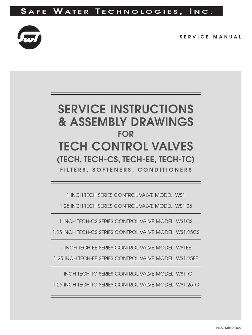
SWT TECH-EE Series User manual

Safe W a t e r t echnologieS, i n c .
EXPANDED TROUBLESHOOTING GUIDE
TROUBLESHOOTING &
ERROR CODE GUIDE
FOR
TECH CONTROL VALVES
(1.5 INCH, 2 INCH, and 2 INCH QC)
FILTERS, SOFTENERS, CONDITIONERS
SEPTEMBER 2012
1.5 INCH TECH-EE SERIES CONTROL VALVE MODEL: WS1.5EE
2 INCH TECH-EE SERIES CONTROL VALVE MODEL: WS2EE
2 INCH QC TECH-EE SERIES CONTROL VALVE MODEL: WS2QCEE

Troubleshooting
Page 2
1. Refer to Tech 1.5, 2, 2QC Control Valves Service Manual.
Problem Possible Cause Solution
1. No display on PC board.
a. No power at electric outlet. a. Repair outlet or use working outlet.
b. Control valve power adapter not plugged
into outlet or power cord end not
connected to PC board connection.
b. Plug power adapter into outlet or
connect power cord end to PC board
connection.
c. Improper power supply. c. Verify proper voltage is being delivered to
PC board.
d. Defective power adapter. d. Replace power adapter.
e. Defective PC board. e. Replace PC board.
2. PC board does not display
correct time of day.
a. Power adapter plugged into electric
outlet controlled by light switch. a. Use uninterrupted outlet.
b. Tripped breaker switch and/or
tripped GFI. b. Reset breaker switch and/or GFI switch.
c. Power outage.
c. Reset time of day. If PC board has
battery backup present, the battery may
be depleted. See “Front Cover and Drive
Assembly” drawing for instructions. 1
d. Defective PC board. d. Replace PC board.
3. Display does not indicate
that water is owing.
a. Bypass valve in bypass position. a. Turn bypass handles to place bypass in
service position.
b. Meter is not connected to meter
connection on PC board.
b. Connect meter to three-pin connection
labeled METER on PC board.
c. Restricted/stalled meter turbine. c. Remove meter and check for rotation or
foreign material.
d. Meter wire not installed securely into
three-pin connector.
d. Verify meter cable wires are installed
securely into three-pin connector labeled
METER.
e. Defective meter. e. Replace meter.
f. Defective PC board. f. Replace PC board.
4. Control valve regenerates
at wrong time of day.
a. Power outage.
a. Reset time of day. If PC board has battery
backup present, the battery may be
depleted. See “Front Cover and Drive
Assembly” drawing for instructions. 1
b. Time of day not set correctly. b. Reset to correct time of day.
c. Time of regeneration set incorrectly. c. Reset regeneration time.
d. Control valve set at “on 0”
(immediate regeneration).
d. Check programming setting and reset to
NORMAL (for a delayed regen time).
e. Control valve set at “NORMAL + on 0”
(delayed and/or immediate).
e. Check programming setting and reset to
NORMAL (for a delayed regen time).
5. Time of day ashes on and
o. a. Power outage.
a. Reset time of day. If PC board has battery
backup present, the battery may be
depleted. See “Front Cover and Drive
Assembly” drawing for instructions. 1

Troubleshooting (Continued)
Page 3
Problem Possible Cause Solution
6. Control valve does not
regenerate automatically
when the REGEN button is
depressed and held.
a. Broken drive gear or drive cap assembly. a. Replace drive gear or drive cap
assembly.
b. Broken piston rod. b. Replace piston rod.
c. Defective PC board. c. Replace PC board.
7. Control valve does not
regenerate automatically but
does regenerate when the
REGEN button is depressed
and held.
a. Bypass valve in bypass position. a. Turn bypass handles to place bypass in
service position.
b. Meter is not connected to meter
connection on PC board.
b. Connect meter to three-pin connection
labeled METER on PC board.
c. Restricted/stalled meter turbine. c. Remove meter and check for rotation or
foreign material.
d. Incorrect programming. d. Check for programming error.
e. Meter wire not installed securely into
three-pin connector.
e. Verify meter cable wires are installed
securely into three-pin connector labeled
METER.
f. Defective meter. f. Replace meter.
g. Defective PC board. g. Replace PC board.
8. Hard or untreated water is
being delivered.
a. Bypass valve is open or faulty. a. Fully close bypass valve or replace.
b. Media is exhausted due to high water
usage.
b. Check program settings or diagnostics
for abnormal water usage.
c. Meter not registering. c. Remove meter and check for rotation or
foreign material.
d. Water quality uctuation. d. Test water and adjust program values
accordingly.
e. No regenerant or low level of regenerant
in regenerant tank. e. Add proper regenerant to tank.
f. Control fails to draw in regenerant. f. Refer to Problem 12 (page 4).
g. Insucient regenerant level in regenerant
tank.
g. Check rell setting in programming.
Check rell ow control for restrictions or
debris and clean or replace.
h. Damaged seal/stack assembly. h. Replace seal/stack assembly.
i. Control valve body type and piston type
mix matched.
i. Verify proper control valve body type and
piston type match.
j. Fouled media bed. j. Replace media bed.
9. Control valve uses too much
regenerant.
a. Improper rell setting. a. Check rell setting.
b. Improper program settings.
b. Check program settings to make sure
they are specic to the water quality and
application needs.
c. Control valve regenerates frequently.
c. Check for leaking xtures that may be
exhausting capacity, or system is
undersized.

Troubleshooting (Continued)
Page 4
Problem Possible Cause Solution
10. Residual regenerant being
delivered to service.
a. Low water pressure.
a. Check incoming water pressure
(water pressure must remain at a
minimum of 25 psi).
b. Incorrect injector size. b. Replace injector with correct size for the
application.
c. Restricted drain line. c. Check drain line for restrictions or debris
and clean.
11. Excessive water in
regenerant tank.
a. Improper program settings. a. Check rell setting.
b. Plugged injector. b. Remove injector and clean or replace.
c. Drive cap assembly not tightened in
properly. c. Retighten the drive cap assembly.
d. Damaged seal/stack assembly. d. Replace seal/stack assembly.
e. Restricted or kinked drain line. e. Check drain line for restrictions or debris
and/or remove kink from drain line.
f. Plugged backwash ow controller. f. Remove backwash ow controller and
clean or replace.
g. Missing rell ow controller. g. Replace rell ow controller.
12. Control valve fails to draw
in regenerant.
a. Injector is plugged. a. Remove injector and clean or replace.
b. Faulty regenerant piston. b. Replace regenerant piston.
c. Regenerant line connection leak. c. Inspect regenerant line for air leak.
d. Drain line restriction or debris cause
excess back pressure.
d. Inspect drain line and clean to correct
restriction.
e. Drain line too long or too high. e. Shorten length and/or height of drain line.
f. Low water pressure.
f. Check incoming water pressure
(water pressure must remain at minimum
of 25 psi).
13. Water running to drain.
a. Power outage during regeneration.
a. Upon power being restored, control will
nish the remaining regeneration time.
Reset time of day.
b. Damaged seal/stack assembly. b. Replace seal/stack assembly.
c. Piston assembly failure. c. Replace piston assembly.
d. Drive cap assembly not tightened in
properly. d. Retighten the drive cap assembly.

Troubleshooting (Continued)
Page 5
Problem Possible Cause Solution
14. E1, Err – 1001, Err – 101
= Control unable to sense
motor movement.
a. Motor not inserted fully to engage pinion,
motor wires broken or disconnected.
a. Disconnect power, make sure motor is
fully engaged, check for broken wires,
make sure two-pin connector on motor is
connected to the two-pin connection on
the PC board labeled MOTOR. Press
NEXT and REGEN buttons for 3 seconds
to resynchronize software with piston
position, or disconnect power supply
from PC board for 5 seconds and then
reconnect.
b. PC board not properly snapped into drive
bracket.
b. Properly snap PC board into drive
bracket. Then press NEXT and REGEN
buttons for 3 seconds to resynchronize
software with piston position, or
disconnect power supply from PC board
for 5 seconds and then reconnect.
c. Missing reduction gears. c. Replace missing gears.
15. E2, Err – 1002, Err – 102
= Control valve motor ran
too short and was unable
to nd the next cycle
position and stalled.
a. Foreign material is lodged in the
control valve.
a. Open up control valve and pull out piston
assembly and seal/stack assembly for
inspection. Press NEXT and REGEN
buttons for 3 seconds to resynchronize
software with piston position, or
disconnect power supply from PC board
for 5 seconds and then reconnect.
b. Mechanical binding.
b. Check piston and seal/stack assembly,
check reduction gears, check drive bracket
and main drive gear interface. Press
NEXT and REGEN buttons for 3 seconds
to resynchronize software with piston
position, or disconnect power supply
from PC board for 5 seconds and then
reconnect.
c. Main drive gear is too tight.
c. Loosen main drive gear. Press NEXT
and REGEN buttons for 3 seconds to
resynchronize software with piston
position, or disconnect power supply
from PC board for 5 seconds and then
reconnect.
d. Improper voltage being delivered to the
PC board.
d. Verify that proper voltage is being
supplied. Press NEXT and REGEN
buttons for 3 seconds to resynchronize
software with piston position, or
disconnect power supply from PC board
for 5 seconds and then reconnect.

Troubleshooting (Continued)
Page 6
Problem Possible Cause Solution
16. E3, Err – 1003, Err – 103
= Control valve motor ran
too long and was unable to
nd the next cycle position.
a. Motor failure during a regeneration.
a. Check motor connections. Press NEXT
and REGEN buttons for 3 seconds to
resynchronize software with piston
position, or disconnect power supply
from PC board for 5 seconds and then
reconnect.
b. Built-up foreign matter on the piston and
stack assemblies creates enough friction
and drag to time-out the motor.
b. Replace piston and stack assemblies.
Press NEXT and REGEN buttons for
3 seconds to resynchronize software with
piston position, or disconnect power supply
from PC board for 5 seconds and then
reconnect.
c. Drive bracket not snapped in properly
and out enough that reduction gears and
drive gear do not interface.
c. Snap drive bracket in properly. Press
NEXT and REGEN buttons for 3 seconds
to resynchronize software with piston
position, or disconnect power supply
from PC board for 5 seconds and then
reconnect.
17. E4 = Control valve does
not regenerate.
a. Interruption or disruption to the
nonvolatile memory.
a. Press and hold SET and DOWN buttons
for 3 to 5 seconds to reset and clear, or
disconnect power supply from PC board
for 5 seconds and then reconnect.
18. Err – 1004, Err – 104
= Control valve motor ran
too long and timed out
trying to reach home
position.
a. Drive bracket not snapped in properly
and out enough that reduction gears
and drive gear do not interface.
a. Snap drive bracket in properly. Press
NEXT and REGEN buttons for 3 seconds
to resynchronize software with piston
position, or disconnect power supply
from PC board for 5 seconds and then
reconnect.
19. Err – 1006, Err – 106,
Err – 116 = MAV/ SEPS/
NHBP/ AUX MAV valve
motor ran too long and
unable to nd the proper
park position.
NOTES:
MAV = Motorized Alternating Valve
SEPS = Separate Source
NHBP = No Hard Water Bypass
AUX MAV = Auxiliary MAV
a. Control valve programmed for ALTA,
ALTb, nHbP, SEPS, or AUX MAV
without having a MAV or NHBP valve
attached to operate that function.
a. Press NEXT and REGEN buttons for
3 seconds to resynchronize software with
piston position, or disconnect power
supply from PC board for 5 seconds and
then reconnect. Then reprogram valve to
proper setting.
b. MAV/ NHBP motor wire not connected to
PC board.
b. Connect MAV/ NHBP motor to PC board
two-pin connection labeled DRIVE. Press
NEXT and REGEN buttons for 3 seconds
to resynchronize software with piston
position, or disconnect power supply
from PC board for 5 seconds and then
reconnect.
c. MAV/ NHBP motor not fully engaged with
reduction gears.
c. Properly insert motor into casing.
(DO NOT force into casing.)
Press NEXT and REGEN buttons for
3 seconds to resynchronize software with
piston position, or disconnect power supply
from PC board for 5 seconds and then
reconnect.
d. Built-up foreign matter on the piston and
stack assemblies creates enough friction
and drag to time-out the motor.
d. Replace piston and stack assemblies.
Press NEXT and REGEN buttons for
3 seconds to resynchronize software with
piston position, or disconnect power supply
from PC board for 5 seconds and then
reconnect.

Troubleshooting (Continued)
Page 7
Problem Possible Cause Solution
20. Err – 1007, Err – 107,
Err – 117 = MAV/ SEPS/
NHBP/ AUX MAV valve
motor ran too short
(stalled) while looking for
proper park position.
NOTES:
MAV = Motorized Alternating Valve
SEPS = Separate Source
NHBP = No Hard Water Bypass
AUX MAV = Auxiliary MAV
a. Foreign material is lodged in
MAV/ NHBP valve.
a. Open up MAV/ NHBP valve and check
piston and seal/stack assembly for
foreign material. Press NEXT and
REGEN buttons for 3 seconds to
resynchronize software with piston
position, or disconnect power supply
from PC board for 5 seconds and then
reconnect.
b. Mechanical binding.
b. Check piston and seal/stack assembly,
check reduction gears, drive gear
interface, and check MAV/ NHBP black
drive pinion on motor for being jammed
into motor body. Press NEXT and
REGEN buttons for 3 seconds to
resynchronize software with piston
position, or disconnect power supply
from PC board for 5 seconds and then
reconnect.

SAFE WATER TECHNOLOGIES, INC.
996 BLUFF CITY BOULEVARD, ELGIN, IL 60120 USA
TELEPHONE 847 888 6900 • FACSIMILE 847 888 6924
E MAIL: info@swtwater.com • WEB SITE: www.swtwater.com
FORM TECH2-TROUBLE
EFFECTIVE
SEPTEMBER 2012
This manual suits for next models
3
Table of contents
Other SWT Control Unit manuals
Popular Control Unit manuals by other brands

Nuie
Nuie TMVSQ2 TMV3 instruction manual

AOP
AOP D Series Installation, operation and maintenance manual

Waters
Waters Pump Control Module II installation guide

Emerson
Emerson Micro Motion user guide

Castle Creations
Castle Creations Mamba Monster X 8s quick start guide

CALEFFI
CALEFFI LEGIOMIX 6000 series Programming manual