Sensitron I/F TCPIP User manual

I/F TCPIP
MANUALE D'INSTALLAZIONE E USO
INSTALLATION AND USER MANUAL
MT3878 21/02/2017 Pag. 1/9
I/F TCPIP
Modulo per l’interfacciamento delle
centrali tramite l’utilizzo della
connessione RJ45, per il controllo
locale tramite rete LAN.
I/F TCPIP
Module for interfacing the control unit
through the RJ45 connection for local
control via LAN.
SENSITRON S.r.l. Viale della Repubblica, 48
20010 CORNAREDO MI - Italy
Ph: + 39 02 93548155 Fax: + 39 02 93548089
E-MAIL: sales@sensitron.it

I/F TCPIP
MANUALE D'INSTALLAZIONE E USO
INSTALLATION AND USER MANUAL
MT3878 21/02/2017 Pag. 2/9
INDICE / INDEX
1INTRODUZIONE.............................................................................................................................................. 3
1INTRODUCTION ............................................................................................................................................. 3
1.1 Descrizione.............................................................................................................................................. 3
1.1 Description............................................................................................................................................... 3
2Montaggio del Modulo................................................................................................................................... 3
2Module mounting........................................................................................................................................... 3
3Preparazione dell’ambiente .......................................................................................................................... 5
3Preparing the environment ........................................................................................................................... 5
4Impostazione del Modulo.............................................................................................................................. 5
4Settings........................................................................................................................................................... 5
5Creazione della porta di comunicazione...................................................................................................... 8
5Creation of the communication port............................................................................................................ 8

I/F TCPIP
MANUALE D'INSTALLAZIONE E USO
INSTALLATION AND USER MANUAL
MT3878 21/02/2017 Pag. 3/9
1 INTRODUZIONE
1 INTRODUCTION
1.1 Descrizione
1.1 Description
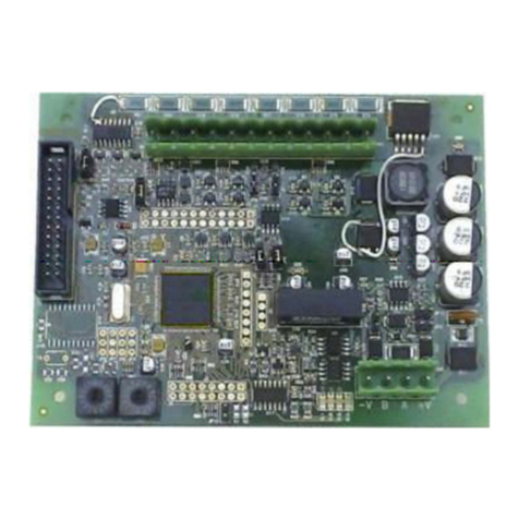
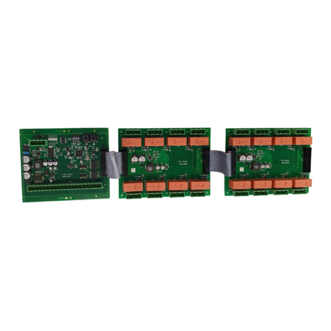
Modulo per l’interfacciamento delle centrali tramite
l’utilizzo della connessione RJ45, per il controllo tramite
rete LAN.
Module for interfacing the control unit through the RJ45
connection for control via LAN.
2 Montaggio del Modulo
2 Module mounting
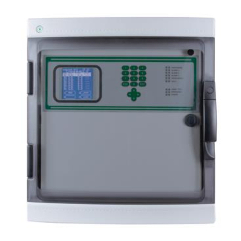
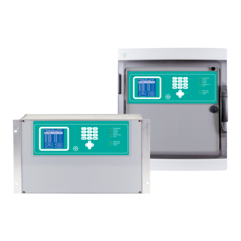
Nel caso si debba montare il modulo su una Centrale
MUSTISCAN ++ Monoscheda, in rack da 19” da 6 unità
o in box plastico.
1. Spegnere la Centrale e aprire lo sportello
anteriore
2. Verificare che il ponticello JP43 che sia chiuso.
3. Inserire l’interfaccia ETHERNET‐RS232 sul
connettore (P2) RS232 della CENTRALE
MULTISCAN++ situato sul pannello posteriore, e
identificabile con la dicitura “SERIAL PORT”.
4. Bloccare l’interfaccia ETERNET‐RS232 con le 3
viti 3MAx6 in dotazione.
5. Richiudere il pannello anteriore.
6. Riaccendere la Centrale e collegare il cavo
ETHERNET all’interfaccia ETHERNET‐RS232.
If you need to mount the module on a single-board
MULTISCAN ++ Control unit, in a 19" 6 units rack or
plastic box.
1. Turn off the Control unit and open the front door
2. Verify that the jp43 bridge is closed.
3. Insert the ETHERNET-RS232 interface on the
RS232 connector (P2) of the MULTISCAN ++
Control Unit on the rear panel, and identified as
"SERIAL PORT".
4. Lock the eternet-RS232 interface with the 3
screws 3MAx6 supplied.
5. Close the front panel.
6. Turn on the Control unit and connect the
ETHERNET cable to the interface ETHERNET-
RS232.

I/F TCPIP
MANUALE D'INSTALLAZIONE E USO
INSTALLATION AND USER MANUAL
MT3878 21/02/2017 Pag. 4/9
Nel caso si debba montare il modulo su una Centrale
MULTISCAN ++ Doppia Scheda, in rack da 19” da 3 unità
o in box metallico.
1. Spegnere la Centrale e sganciare il pannello
posteriore, svitando le 10 viti che lo bloccano sul
RACK di alluminio.
2. Verificare che il ponticello JP43 sia chiuso sul
lato interno del pannello posteriore.
3. Inserire l’interfaccia ETHERNET‐RS232 sul
connettore (P2) RS232 della CENTRALE
MULTISCAN++ situato sul pannello posteriore, e
identificabile con la dicitura “SERIAL PORT”.
4. Bloccare l’interfaccia ETERNET‐RS232 con le 3
viti 3MAx6 in dotazione dalla parte interna del
pannello posteriore.
5. Riagganciare il pannello posteriore al RACK di
alluminio, riavvitando le 10 viti.
6. Riaccendere la Centrale e collegare il cavo
ETHERNET all’interfaccia ETHERNET‐RS232.
If you need to mount the module on a Dual Card
MULTISCAN ++ Control unit, in a 19" 3 units rack or
metal box.
1. Turn off the Control unit and release the back
cover by unscrewing the 10 screws that block it
on the aluminium RACK.
2. Verify that the jp43 jumper is closed on the inside
of the rear panel.
3. Insert the ETHERNET-RS232 interface on the
RS232 connector (P2) of the MULTISCAN ++
control unit on the rear panel, and identified as
"SERIAL PORT".
4. Lock the eternet-RS232 interface with the 3
screws 3MAx6 supplied from the inside of the
rear panel.
5. Replace the rear panel to the aluminium RACK,
10 screws.
6. Turn on the control unit and connect the
ETHERNET cable to the interface ETHERNET-
RS232.

I/F TCPIP
MANUALE D'INSTALLAZIONE E USO
INSTALLATION AND USER MANUAL
MT3878 21/02/2017 Pag. 5/9
3 Preparazione dell’ambiente
3 Preparing the environment
I moduli XPORT dell’I/F TCPIP, sono stati
pre‐programmati per funzionare in DHCP, ovvero il loro
indirizzo IP lo otterranno automaticamente dal master
della rete. Questo affinché in prima battuta sulla rete non
siano generati potenziali conflitti di doppi indirizzamenti.
A questo punto occorre installare sul P.C. due programmi
che comunicheranno con le centrali, scaricabili dal sito
LANTRONIX.
“Device Installer”
https://www.lantronix.com/products/deviceinstaller/
“CPR” https://www.lantronix.com/products/com-port-
redirector/
The modules XPORT of the I/F TCPIP, have been pre-
programmed to operate in DHCP, so, their IP address will
automatically get from the network master. This for not
generating potential conflicts of double addressing on the
network.
You must now install on your P.C. two programs, from
LANTRONIX website, to communicate with the control
unit.
“Device Installer”
https://www.lantronix.com/products/deviceinstaller/
“CPR” https://www.lantronix.com/products/com-port-
redirector/
4 Impostazione del Modulo
4 Settings
La prima volta che si lancia il programma potrebbe
comparire un messaggio in cui non si riconosce nessuna
rete.
In questo caso occorre selezionare sotto il menu “Tools”
la voce “Options” e selezionare “Connessione alla rete
locale (LAN)”, cliccare “Apply” e dopo “OK” per ritornare
nella schermata principale.
1. Nella schermata principale cliccare su “Search”
per cercare il modulo/i.
2. Dopo qualche secondo nella finestra di sinistra
dovrebbe comparire il nome del modulo “xPort”
con il suo indirizzo IP (assegnato
automaticamente dalla rete in DHCP) il suo
Hardware‐Address Univoco (MAC‐Address), e lo
status che dovrebbe essere Online.
Il fine ultimo è quello di assegnare un Virtual Com Port sul
P.C. che comunicherà con la centrale che farà riferimento
all’indirizzo IP del modulo XPORT. Per far ciò occorre
cambiare l’indirizzo IP del modulo in un indirizzo IP
Statico, i. In questo modo spegnendo e riaccendendo il
sistema l’indirizzo IP del modulo sarà sempre lo stesso e
la Virtual Com Port assegnata sul P.C. (che fa riferimento
all’indirizzo IP del modulo) funzionerà senza problemi.
3. Selezionare nella voce di sinistra il modulo, e
nella barra dei comandi cliccare su “ASSIGN IP”.
4. Si apre una finestra in cui occorre selezionare la
voce “Assign a specific IP address”, premere il
pulsante “Next”.
5. Compare il settaggio attuale del modulo definito
su tre voci modificabili: “IP address”, “Subnet
mask” e Default gateway. Modificare le voci che
interessano in base all’impostazione della rete
ETHERNET e cliccare Next, e nella finestra
successiva pigiare il pulsante “Assign”. Dopo
qualche secondo di attesa in cui le nuove
impostazioni e il comando di riavvio sono inviati
al modulo,
The first time you launch the program the network could
not recognized the LAN.
In this case, you must select under the "Tools" menu the
item "Options" and select "Local Area Network (LAN)",
click "Apply" and then "OK" to return to the main screen.
1. On the main screen click "Search" to find the
module/s.
2. After a few seconds on the left window you
should see the name of the module "xPort” with
its IP address (automatically assigned by the
DHCP network), its Unique Hardware-Address
(MAC Address) and the status that should be
Online.
The ultimate goal is to assign a Virtual Com Port to the
P.C. that will communicate with the control panel. This
control panel will refer to the IP address of the module
XPORT. To do this we need to change the IP address of
the module into a static IP address, i. In this way, turning
off and on the system's the IP address of the module will
be always the same and the Virtual Com Port assigned to
the P.C. (Which refers to the module's IP) will work fine.
3. Select the module on the left item, and click
"ASSIGN IP” on the command bar".
4. It opens a window where you must select "
Assign a specific IP address” than press the
button "Next".
5. You will see the current setting of the module
defined in three editable voices: "IP address",
"Subnet Mask", and Default gateway. Change the
setting of the Ethernet network and click “Next”.
Than, press the "Assign" button. After a few
seconds, in which the new setting and the restart
command are sent to the module,

I/F TCPIP
MANUALE D'INSTALLAZIONE E USO
INSTALLATION AND USER MANUAL
MT3878 21/02/2017 Pag. 6/9
6. Cliccare di nuovo il comando “Search” sulla
barra dei comandi del “Device Installer” per
rivedere il modulo con i nuovi dati nella finestra
di sinistra.
A questo punto occorre sapere quale sarà la velocità di
comunicazione sulla linea RS232 con cui la Centrale
MULTISCAN++ dovrà rispondere a comandi ricevuti dal
P.C.; questo dipende anche dal programma usato sul
P.C. Le impostazioni di default della linea seriale RS232
sulla Centrale sono: 115.200 Bps, 8bits, 1stop bit, No
parity. Per verificare le impostazioni settate sulla Centrale
è sufficiente:
a) Manovrando sul tastierino e guardando il display
LCD della Centrale, andare nella voce “MENU”
b) Selezionare la voce “SYSTEM INFO”, verso il
fondo dell’elenco delle informazioni visualizzate
devono essere visibili: “SLAVE Adr. 1” e “BAUD:
115200”.
Nel manuale tecnico della Centrale è spiegato come
cambiare eventualmente il BAUD RATE. Le interfacce
ETHERNET‐RS232 sono programmate per comunicare
con la centrale alla velocità di 115.200 Bps, se si deve
cambiare la velocità occorre modificare anche questo
parametro nel modulo XPORT‐I/F TCPIP.
Per verificare/cambiare i parametri del modulo XPORT‐
I/F TCPIP, sempre nel “Device Installer”
a) Cliccare due volte sul nome del modulo trovato,
b) Selezionare il tab “Web Configuration”,
c) Cliccare sulla Freccia Verde (Navigate to
http://xx.xx.xx.xx).
Si aprirà una “dialog box” in cui si chiede di inserire
Nome utente e Password, cliccare su OK senza inserire
nulla.
A questo punto si è nel WEB‐Server del modulo XPORT‐
I/F TCPIP (Device Server Configuration Manager),
selezionare sotto “Channel1”, “Serial settings”. Sono a
questo punto visibili e modificabili i parametri di
comunicazione seriale fra l’interfaccia ETHERNET‐RS232
e la Centrale MULTISCAN++.
a) Modificare se necessario solo la voce
BAUD‐RATE e premere OK.
b) Nel menu a sinistra cliccare “Apply Settings” e
attendere il completamento dell’operazione.
Per controllare l’effettiva modifica del parametro occorre
ripetere il comando “Search”.
6. Click "Search" on the command bar of the
"Device Installer" to review the new settings in
the left window.
Now we need to know what will be the speed of
communication on the RS232 line on which the
MULTISCAN ++ have to respond to commands received
from the P.C.; this also depends on the program used on
the P.C. The RS232 serial line default settings on the
Control unit are: 115200 bps, 8bits, 1stop bits, no parity.
To check the settings on the Control unit you have to:
a) Manoeuvring the keypad and viewing the LCD
display of the control unit, go under "MENU"
b) Select the "SYSTEM INFO", towards the bottom
of the list of the information displayed, must be
visible: "SLAVE Adr. 1 "and" BAUD: 115200 ".
The technical manual of the Control unit explains how to
change the BAUD RATE. The ETHERNET-RS232
interfaces are programmed to communicate with the
control panel at a rate of 115.200 Bps. If you wish to
change the speed you must modify this parameter also in
the module XPORT- I/F TCPIP.
To check / change the XPORT- I/F TCPIP parameters, in
the "Device Installer"
a) Double click on the name of the module found,
b) Select the "Web Configuration" tab,
c) Click on the Green Arrow (Navigate to
http: //xx.xx.xx.xx).
This will open a "dialog box" that prompts you to insert
username and password, click OK without entering
anything.
At this point you are in the WEB-Server XPORT- I/F
TCPIP module (Device Server Configuration Manager),
select under "Channel 1”, “Serial settings". At this point
are visible and editable the serial communication
parameters of the ETHERNET-RS232 interface and the
MULTISCAN ++ control unit.
a) Change if necessary only the voice BAUD-RATE
and press OK.
b) On the left menu, click “Apply Settings”and wait
for the operation end.
For controlling the actual parameter change is necessary
to repeat the command "Search".

I/F TCPIP
MANUALE D'INSTALLAZIONE E USO
INSTALLATION AND USER MANUAL
MT3878 21/02/2017 Pag. 7/9
Per selezionare il protocollo di comunicazione Modbus
TCP è necessario andare nella sezione Channel1 –
Connection e dal menu a tendina “Protocol:” selezionare
la voce Modbus.
To select the Modbus TCP communication protocol is
necessary to go in the section Channel 1 - Connection
and in the "Protocol" menu select the item Modbus.

I/F TCPIP
MANUALE D'INSTALLAZIONE E USO
INSTALLATION AND USER MANUAL
MT3878 21/02/2017 Pag. 8/9
5 Creazione della porta di
comunicazione
5 Creation of the communication
port
Adesso occorre assegnare al modulo XPORT‐I/F TCPIP
una Virtual Com Port sul P.C. che interrogherà le centrali.
Lanciare il programma “CPR‐Manager” sul P.C.
1. Cliccare “Search For Devices”
Now you must assign to XPORT- I/F TCPIP module a
Virtual Com Port on the P.C.
Launch the "CPR Manager" program on the P.C.
1. Click "Search For Devices"
2. Nell’elenco “Device List” in fondo alla finestra,
dovrebbe comparire il modulo preceduto dal suo
indirizzo IP.
2. In the "Device List" at the bottom of the
window, you should see the form preceded by
its IP address.
3. Cliccare sul comando “Add/Remove”, si aprirà una
finestra con l’elenco di tutte le “Com Ports”
disponibili e non (quelle non disponibili sono in
colore grigio e non selezionabili).
3. Click on "Add / Remove", it will open a window
with a list of all the "Com Ports" available and
not available (those not available are in gray
colour and not selectable).
4. Selezionare una “Com” disponibile e cliccare OK.
4. Choose a "Com" available and click OK.
5. Fare doppio clic sulla nuova Com Port, quella che
ha l’aggiunta (New). Si apre la nuova finestra
“Settings”, in cui molte voci sono in rosso.
5. Double-click the new Com Port, the one that
has the addition (New). It opens the new
"Settings" window, where many items are in
red.

I/F TCPIP
MANUALE D'INSTALLAZIONE E USO
INSTALLATION AND USER MANUAL
MT3878 21/02/2017 Pag. 9/9
6. Andare nella finestra “Device List” al fondo e fare
doppio clic sull’indirizzo IP del modulo XPORT
trovato in precedenza.
6. Go to the "Device List" window on the bottom
and double-click the IP address of the XPORT
module found earlier.
7. Automaticamente nella finestra “Settings” nella
tabella Host sarà inserito l’indirizzo IP del modulo e
la sua TCP Port.
7. Automatically in the "Settings" window in the
Hosts table will be added the module IP
address and its TCP Port.
8. Premere il pulsante “Save” nei comandi e dare la
successiva conferma. La finestra “Settings” sarà
riscritta con tutte le informazioni in nero. Chiudere il
programma CPR.
9. Nel pannello di controllo di Windows sotto Sistema,
Gestione dispositivi e Porte (COM e LPT), si potrà
vedere la nuova linea seriale disponibile. N.B. la
verifica in questo esempio è stata fatta su di un
P.C. con Windows 7.
Adesso la Centrale MULTISCAN++ potrà essere interrogata
o configurata utilizzando la nuova porta seriale attraverso la
rete ETHERNET.
8. Press the "Save" button and give the
subsequent confirmation. The "Settings" will
be rewritten with all the information in black.
Close the CPR program.
9. In the Windows Control Panel under System,
Device Manager and Ports (COM & LPT), you
will see the new available serial line. N.B. this
example was done with a P.C. with Windows
7.
Now the MULTISCAN ++ control unit can be configured
using the new serial port through the Ethernet network.
Table of contents
Other Sensitron Control Unit manuals
