Deif WSI User manual

DEIF
A/S
Ultrasonic wind measuring system
WSI, WSDI, WSS or WSS-L
4189350034A
User’s Ma
nual
•Sea-waterproof construction
•Accurate read-out of wind direction and wind speed
•NMEA data output
•1-3 displays per sensor
•Based on ultrasonic principle - no moving parts
•WSS version has a built-in, automatically activated
heating element to prevent ice
DEIF A/S, Frisenborgvej 33 Tel.: +45 9614 9614, Fax: +45 9614 9615
DK-7800 Skive, Denmark E-mail: deif@deif.com, URL: www.deif.com

WSI, WSDI, WSS or WSS-L User’s Manual
DEIF A/S
Page 2 of 19
Table of contents
1.
GENERAL INFORMATION ................................................................................................... 3
A
PPLICATION
............................................................................................................................... 3
D
ESIGN
....................................................................................................................................... 3
2.
WARNINGS AND GENERAL INFORMATION...................................................................... 5
3.
MOUNTING AND CONNECTING THE WIND SENSOR ...................................................... 6
P
LACING OF WIND SENSOR
........................................................................................................... 6
C
ABLE CONNECTION
..................................................................................................................... 7
4.
CONFIGURATION OF THE DISPLAY .................................................................................. 9
C
OMMUNICATION TYPE
NMEA...................................................................................................... 9
R
EAD
-
OUT OF WIND DIRECTION
..................................................................................................... 9
A
UX
.
SUPPLY FOR THE DISPLAY
..................................................................................................... 9
5.
TROUBLESHOOTING......................................................................................................... 12
F
AULT
-
FINDING
.......................................................................................................................... 12
6.
TECHNICAL INFORMATION .............................................................................................. 14
N
UMBER OF CONNECTED RECEIVERS TO THE
NMEA
OUTPUT
....................................................... 15
T
YPE NUMBERS
.......................................................................................................................... 15
S
PARE PARTS
............................................................................................................................ 15
7.
DRAWINGS ......................................................................................................................... 16

WSI, WSDI, WSS or WSS-L User’s Manual
DEIF A/S
Page 3 of 19
1. General information
IMPORTANT: In this document, the term WSS will represent both WSS and WSS-L if no specific
mentioning of the WSS-L is made.
Application
The wind measuring system WSS is a fast responding and accurate system designed for
measurement of wind speed and wind direction on-board ships. The wind measuring system
WSS is classified for residential, commercial and light industry plus industrial environment.
This system offers the advantage of reading the measuring results from several locations on-
board, e.g. at control desks both on the bridge and on the bridge wings.
The displays are provided with data output for serial transfer of measuring values to the
navigation computer of the ship via NMEA protocol.
The system indicates relative wind speed and wind direction. If indication of absolute wind speed
and wind direction is required, these values must be calculated separately.
Design
The wind measuring system type WSS consists of three components: A wind sensor, an
interface box and 1-3 displays for indication of wind speed and wind direction.
Anemometer sensor type WSS or WSS-L
The sensor is based on 3 ultrasonic transducers arranged in a triangle for measuring of wind
speed and wind direction. By measuring the time it takes the ultrasound to travel from one
transducer to the other two, the wind speed and the direction can be measured.
The wind sensor is available in two versions:
- The WSS with a built-in heater, which will automatically engage when risk of icing occurs
during low temperatures.
- The WSS-L without the heater is intended for applications in geographic areas where the
risk of icing is very low or where occasional dropouts caused by icing are acceptable.
WSS interface box type WSI
The interface box is connected between the sensor and the display. The interface box has to be
supplied from an 18…32V DC supply able to deliver 0.9A at 24V DC (1.25A at 18V DC), and it
will then supply the ultrasonic transducers and the built-in heating element and at the same time
convert the data signal for wind direction and wind speed into a TTL signal intended for the
WSDI display(s). This is to make it possible to replace an existing wind sensor type 879.3c with
our new sensor type WSS and to be able to connect the sensor to the existing display type
WSDI. Besides, the already mounted cable for the sensor can still be used.
Display type WSDI
The display(s) is (are) equipped with a digital display for read-out of wind speed plus a circle of
red LEDs for indication of wind direction. In addition, the display(s) also has (have) an output for
the NMEA communication.
By means of 3 push-buttons on the front panel the light intensity can be set to an adequate level,
and it is possible to choose between indication of wind speed in either m/s or KTS.
The light intensity may be set at 8 different levels. The two push-buttons "" and "" are used
to increase/decrease the light intensity. With each push on the "" button the light intensity is

WSI, WSDI, WSS or WSS-L User’s Manual
DEIF A/S
Page 4 of 19
increased by one level, while each push on the "" button decreases the light intensity by one
level correspondingly.
The "MODE" key is used to switch measuring mode, which enables reading of the
measurements either in m/s or in KTS. The selected mode is indicated by means of a red LED
in m/s or KTS respectively, just below the speed indication.

WSI, WSDI, WSS or WSS-L User’s Manual
DEIF A/S
Page 5 of 19
2. Warnings and general information
Do not expose the plastic part of the wind sensor to any torque when
mounting the sensor; the tools used for fastening are only to be applied on
the actual tap.
For cleaning of the wind sensor, if necessary, only use water with a little dish
washer soap.
Avoid paint on the plastic parts of the wind sensor, especially on the 3
ultrasonic sensors, as paint will prevent correct function (measurement of
wind speed and wind direction).
Make sure that the WSS wind sensor is grounded according to the installation
instructions
.
If there is a high risk of birds landing on top of the WSS and thereby
interrupting wind measurements or even damaging the sensor heads (the
black rubber heads may attract some birds), it is highly recommended to use
the “WSS bird avoidance kit”!
WSI, WSDI, WSS or WSS-L User’s Manual
DEIF A/S
Page 6 of 19
3. Mounting and connecting the wind sensor
Placing of wind sensor
Ideally, the wind sensor should be placed far from large objects that might influence the measuring
results; however, in practice this is normally not possible on-board a ship. The best result is
achieved by placing the wind sensor at the top of a mast in the opposite end of the superstructure.
Placing the sensor just above the superstructure is disadvantageous, especially where the
superstructure consists of wide side faces, over which the wind is forced. This may result in
turbulence, velocities and wind directions that are out of proportion to the actual, undisturbed
wind speed and wind direction.
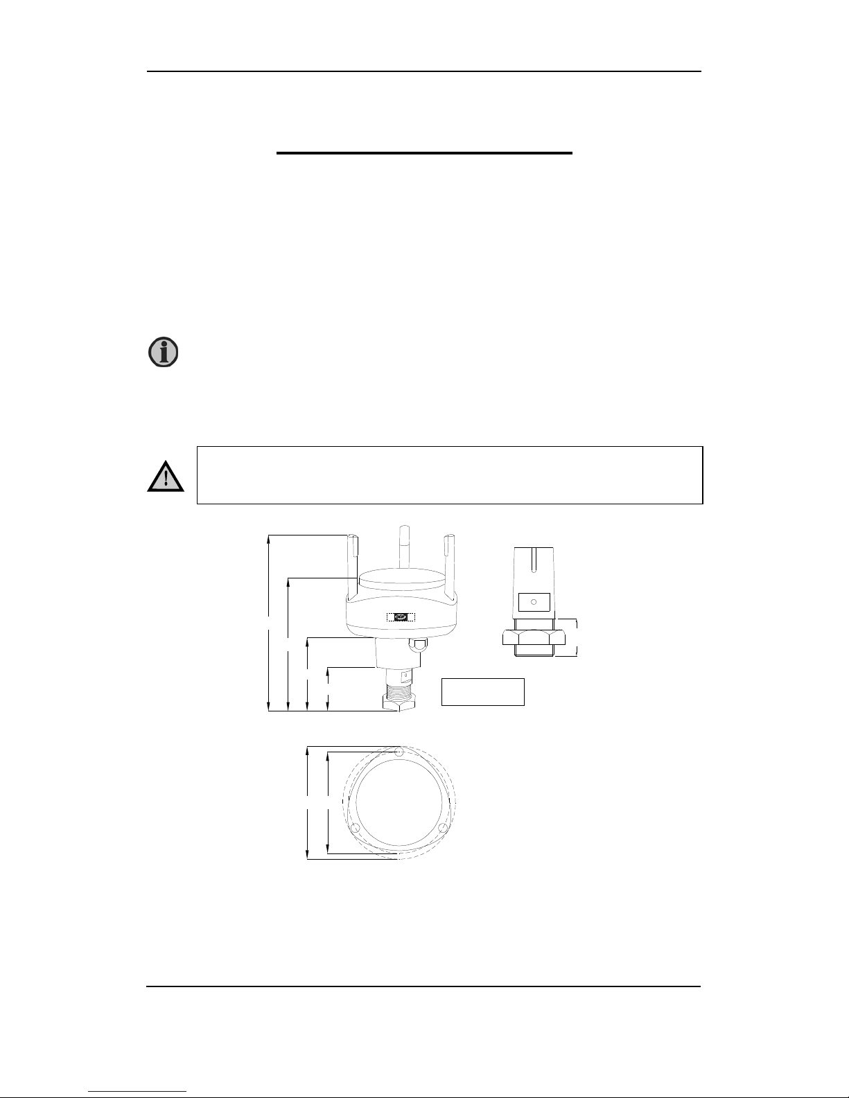
The wind sensor is intended for installation on a vertical socket or a tube using the tap mounted on
the wind sensor on delivery. See the drawing below for dimensions of the tap. The tap is not to be
removed from the wind sensor, as this will damage the waterproof sealing.
To ensure that the display represents the precise wind direction according to the ship, the wind
sensor must be adjusted correctly. I.e. when mounting the wind sensor, the arrow printed on the
bottom of the sensor must point towards the stem of the ship, and on land-based installations
the arrow must point towards north.
Do not expose the plastic part of the wind sensor to any torque when
mounting the sensor, the tools used for fastening are only to be applied on
the actual tap.
Keep away from the funnel.
82.4
149.8
198.0
49.5
127.0
114.0
25.0
¾” thread.
WSI, WSDI, WSS or WSS-L User’s Manual
DEIF A/S
Page 7 of 19
Cable connection
The wind sensor is supplied with 2 metres fixed cable. From factory the cable is connected to the
sensor via a waterproof gland, and this must not be replaced by another cable; the cable is
extended by using a standard connection box or the optional IP67 connector kit for WSS.
In order to protect the wind sensor and the personnel in the best possible way from lightning
strokes, use a lightning rod installed with the tip at least one metre above the wind sensor. The
lightning rod must be properly grounded in compliance with all applicable safety regulations. The
wind sensor cable screen and the installation cable screen must be connected.
For further protection of the cable between the wind sensor and the connection box, as well as the
installation cable between the connection box and the interface box, it is recommended to use a
metal conduit pipe. If the instrument is installed in a metal panel, this panel has to be carefully
earthed, as well as the instrument itself.
Installation cable, e.g. UL2464 18AWG4C + AE, 4 x 0.75mm
2
screened, max. 300m, and max.
70nF capacity between the signal conductors. Suitable extension cable is available from DEIF.
Connection of the WSS wind sensor
Cable colour Function Note
Black Supply voltage - 30V DC supply for the WSS wind sensor
Red +
Orange RS485 comm. A Wind speed and direction data output
Brown B
Shield Cable shield Shield is connected to the stainless steel tap
inside the WSS
Connection of the WSS interface box WSI
Pin no. Function Note
1 Supply voltage - 24V DC (1.25A) supply for the interface box
2 +
3 NC
4 RS485 comm. A Wind speed and direction data from the wind
sensor
See IMPORTANT note!
5 B
6 GND
7 Power supply
out + 30V DC supply for the wind sensor
8 NC
9 -
10 Wind speed TTL out Wind speed and direction data to the display
type WSDI
11 Direction TTL out
12 Common GND
13 NC Do not connect
14 NC
15 NC
IMPORTANT!
The WSS stainless steel mounting base shall be connected to the ship’s earth
cable (or steel hull).

WSI, WSDI, WSS or WSS-L User’s Manual
DEIF A/S
Page 8 of 19
IP67 Connector kit assembly (OPTIONAL)
WSS/WSS-L
fixed cable
Male
connector
Connector
pin no.
WSS extension
cable xx meters
Female
connector
Signal comments
Black (-) 1 Black (-) 30V DC Supply for WSS/WSS-L
Red (+) 2 Red (+)
Orange 3 Orange RS485 Comm. from WSS/WSS-L
Brown 4 Brown
Screen 5 Screen Cable screen
Note: Male and female connectors must be soldered to the respective cables!
WSI, WSDI, WSS or WSS-L User’s Manual
DEIF A/S
Page 9 of 19
4. Configuration of the display
Communication type NMEA
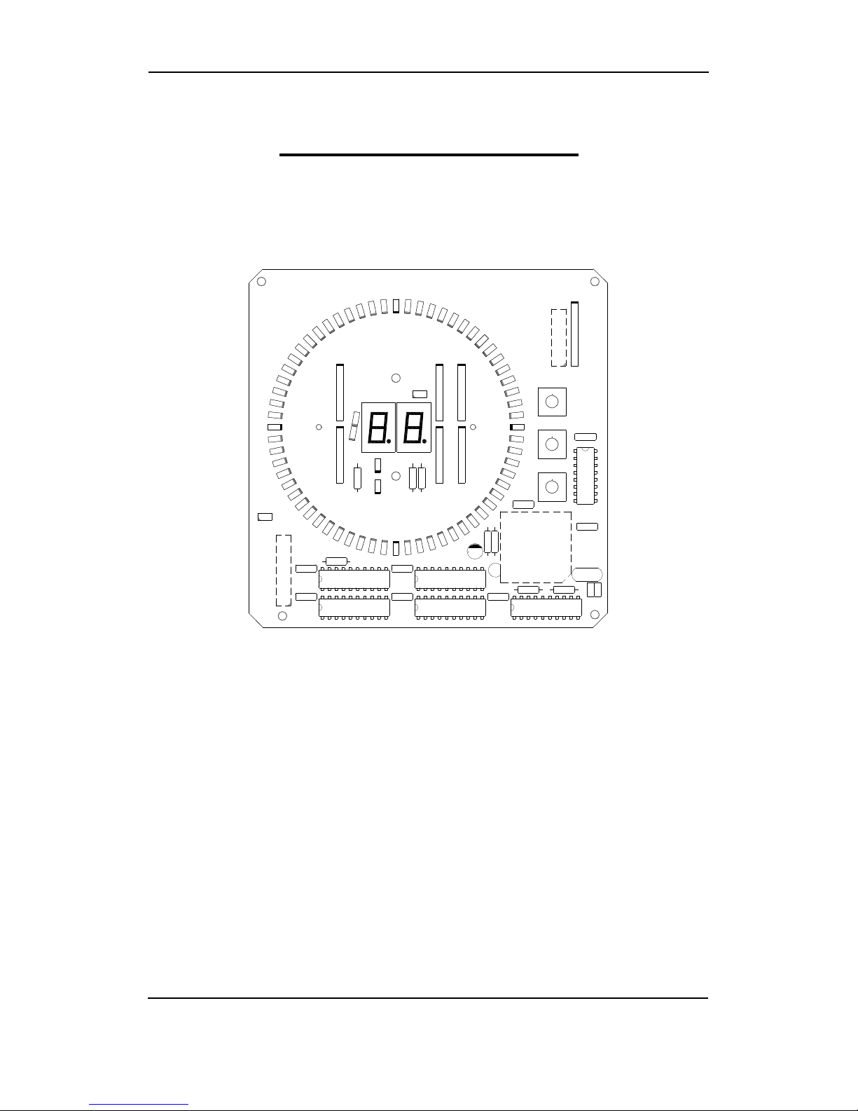
Change between NMEA 1.5 and NMEA 2.x-3.0 is possible by removing the back plate and
changing the position of the jumper located on the rear side of the display PCB, see the drawing
below.
First locate the 2 x 8 pole plug (marked JP1).
NMEA 2.x-3.0 is activated by short-circuiting the two pins at position 1 on JP1 (facing the CPU,
marked U8).
NMEA 1.5 is activated by removing the short circuit across the two pins at position 1 on JP1 (facing
the CPU, marked U8).
Read-out of wind direction
The indication of wind direction can be adjusted 180° compared to standard. Read-out of wind
direction on the display is adjusted by 180°, meaning 360°pointing astern of the ship. This function
is activated by short-circuiting the two pins at position 3 on JP1.
Please notice that the 180°adjusted wind indication has no influence on the NMEA output.
Aux. supply for the display
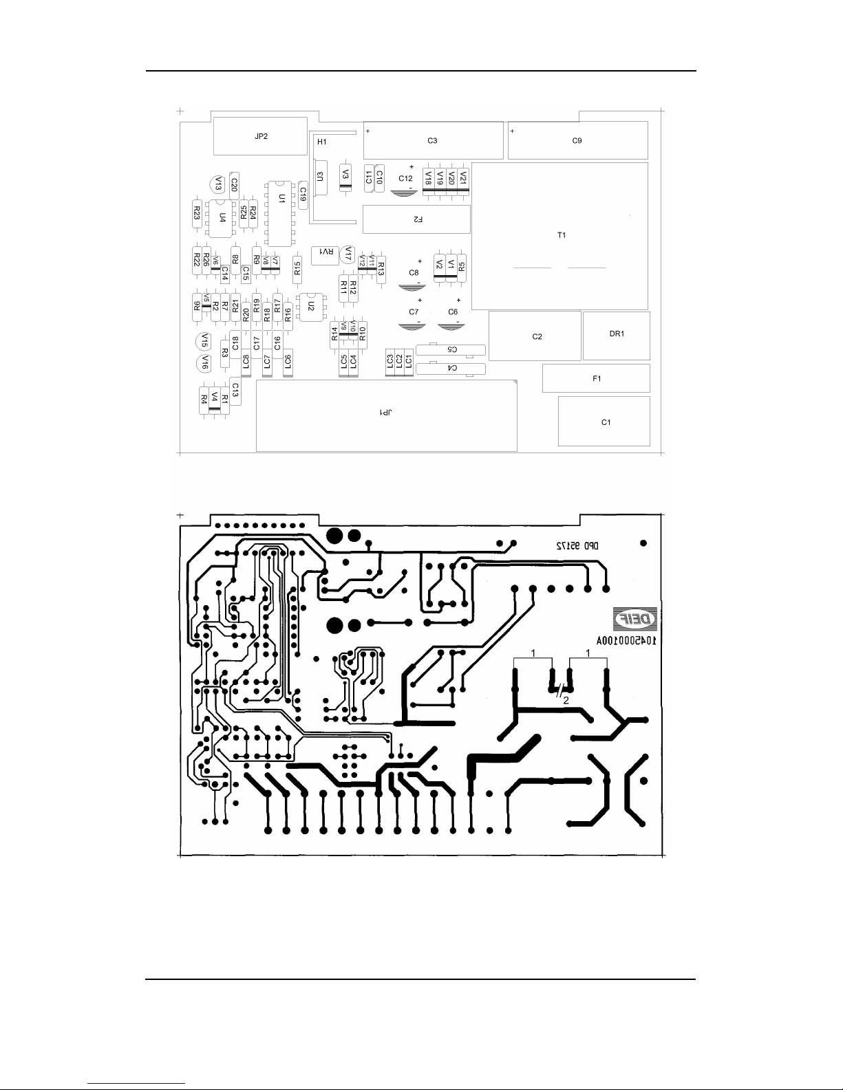
The display type WSDI can be supplied from 220V AC or 110V AC. If change of the supply is
needed, the rear plate is removed and the power/input PCB is carefully pulled out, see the drawing
on the next page.
C1
C2
C3
C4
C5
C6
C7 C8 C9
C10
C11
C12
C13
D1 D2 D3 D4 D5 D6 D7D8 D9
D10
D11
D12
D13
D14
D15
D16
D17
D18
D19
D20
D21
D22
D23
D24
D25
D26
D27
D28
D29
D30
D31
D32
D33
D34
D35
D36
D37
D38
D39
D40
D41
D42
D43
D44
D45
D46
D47
D48
D49
D50
D51
D52
D53
D54
D55
D56
D57
D58D59
D60
D61D62
D63D64
D65
D66
D67D68
JP1
JP2
R1
R2
R3
R4
R5
R6
R7
R8
R9
R10
R11
R12 R13
R14
R15
S1
S2
S3
U1
U2
U3 U4 U5
U6U7
U8
U9
U10
Y1
8
7
6
5
4
3
2
1
+
-
+-
1045000090A
+
+
+
+
+
+
+
+
+
+
+
+
+
+
+
+
+
+
+
+
+
+
+
+
+
+
+
+
+
+
+
+
+
+
+
+
+
+
+
+
+
+
+
+
+
+
+
+
+
+
+
+
+
+
+
+
+
+
+
+
+
+
+
+
+
+
+
+
-
+
WSI, WSDI, WSS or WSS-L User’s Manual
DEIF A/S
Page 10 of 19
Change from 110V AC to 220V AC by removing the jumpers across 1 and remounting the jumper
across 2.
Change from 220V AC to 110V AC by mounting the 2 jumpers across 1 and removing the jumper
across 2 (or by breaking the copper line by means of a knife).

WSI, WSDI, WSS or WSS-L User’s Manual
DEIF A/S
Page 11 of 19
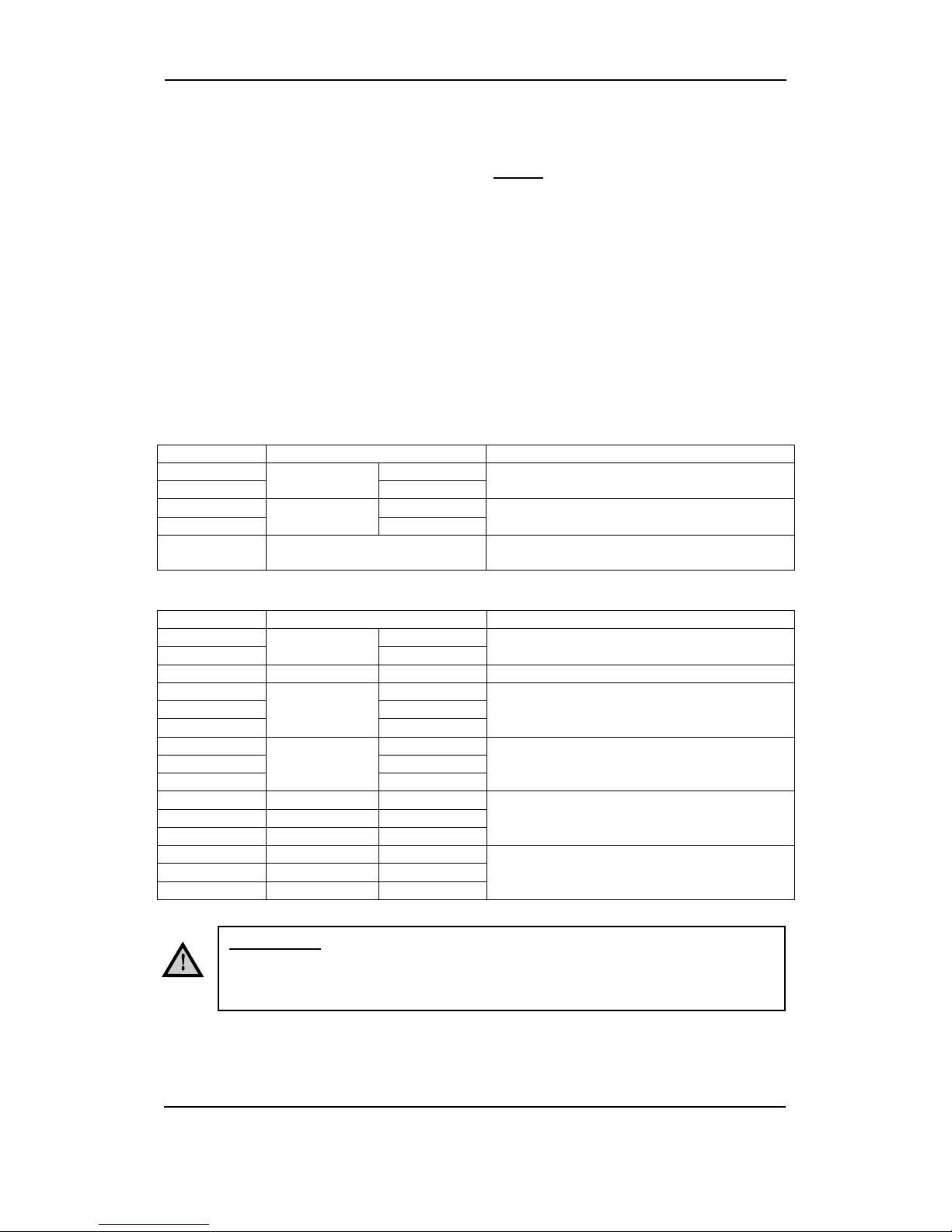
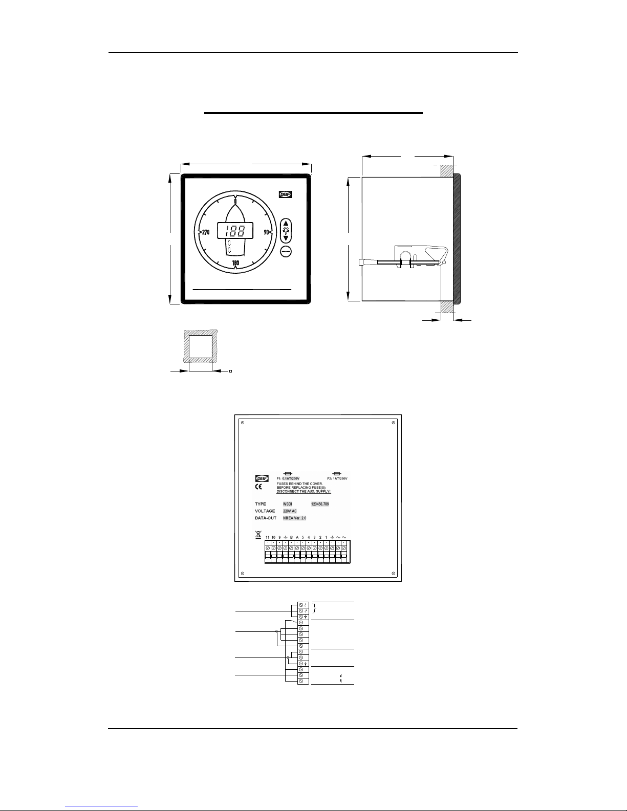
Connection of the display type WSDI
Pin no. Function Note
AC Supply 220V AC or
110V AC To change from 220V AC to 110V AC or vice
versa, see page 8
AC
GND EARTH The ship’s hull, it is not necessary to connect this
terminal
1 AUX +5V
DC External mode
control For external dimmer and read-out of m/s or KTS in
the display
2 0V Input from
WSS interface
box
Terminal 12 on the interface box, WSI
3 Wind speed Terminal 10 on the interface box, WSI
4 Direction Terminal 11 on the interface box, WSI
5 Screen The cable screen. Do not connect the other end
A Signal NMEA NMEA0183 version 1.5 or 2.x-3.0, see page 7.
B Return
Screen The cable screen. Do not connect the other end
9 Mode shift m/s or KTS Read-out in the display
10 Dimmer
Decrease illumination
11 Dimmer Increase illumination

WSI, WSDI, WSS or WSS-L User’s Manual
DEIF A/S
Page 12 of 19
5. Troubleshooting
Fault-finding
It is assumed in the following guidance that the fault-finding is carried out on a system that has
been working. However, some of the procedures may also be useful when installing and
commissioning the first time. First, the purpose is to locate the cause of e.g. a missing supply
voltage, a blown fuse, a defective wind sensor, a defective interface box, a defective display or fault
in the cable connection. Further fault-finding and possible repair must be carried out by DEIF A/S.
No light in the instrument
There is no light in the LED circle, nor in the display, the “m/s” or the “KTS” LED.
It is most likely caused by a fault in the internal 5V DC supply that supplies the electronic, meaning
that the fault is possibly due to the fact that one of the two internal fuses has blown. The fuses are
marked F1 and F2. F1 is the fuse for the aux. supply (220V AC or 110V AC) and the type is a 1A
slow blow fuse, and F2 is the fuse for the 5V DC internal supply and the type is a 0.1A slow blow
fuse. See the drawing on page 8.
Check that the correct AC supply voltage (220V AC or 110V AC) is present on the terminals
marked “≈”. The correct supply voltage is indicated by means of a cross (x) on the nameplate
located on the rear side of the display.
Then check the 5V DC between terminals “1” (+5V) and “2” (0V) on the display. If the AC supply
voltage is present on the terminals but 5V is missing, a fuse has probably blown. The rear panel
of the display housing is then removed, and the defective fuse is replaced.
Flashing display
If the aux. supply voltage is less than the nominal voltage -20%, the voltage for the built-in
processor is inadequate and the result is a flashing display.
If the speed is indicated as fixed “0” and the display is jumping from 0 degrees to approx. 240
degrees, the 24V DC supply is not able to deliver 1.25A.
Light in the display but inaccurate reading of wind speed and direction
Check the voltage level for wind speed input for the display between terminal “2” (0V) and terminal
“3” on the display to approx. +2.5V DC. During this test the sensor must be exposed to a stable
wind flow (no wind speed = 5V). Then check the voltage level for wind direction input between
terminal “2” and “4” to approx. 1-3V DC. (Be aware that the measurement will fluctuate). If the
voltage levels measured differ from the above, the fault can be related to either the WSS interface
box or the WSS wind sensor itself.
Checking the WSS interface box
First check the voltage connected to terminal “2” (+) and terminal “1” (-) on the interface box. The
voltage level has to be in the range 18-32V. Then check the voltage supply for the wind sensor on
terminal “7” (+) and “9” (-). The voltage level must be 30V DC ±0.5V.
Checking the WSS wind sensor
Check the voltage level on terminals “4” (A) and “5” (B) with respect to terminal “6” (-) on the
interface box. The voltage level measured on terminal “4” must be approx. 2-3V DC, and the
voltage level on terminal “5” must be approx. 2-3V DC. If the voltage differs from the above, the
fault can be related to the cable connection or the wind sensor. Then climb the mast and measure
the voltage level between the red wire (+) and the black wire (-). The voltage has to be 30V DC

WSI, WSDI, WSS or WSS-L User’s Manual
DEIF A/S
Page 13 of 19
+0.5/-7V. If the voltage level is OK, then disconnect the brown and orange wires in the connection
box. Check the voltage level on the brown and the orange wires with respect to the black wire on
the cable end connected to the interface box. The voltage level measured on the brown wire must
be 2.5V ±0.5V DC, and the voltage level measured on the orange wire must be 2.5V DC ±0.5V. If
the voltage levels are OK, the fault is related to the wind sensor and a replacement is necessary.
On the other hand, if the voltage level differs from the above, the fault is related to the cable.
Cable failure
If the read-out of the wind speed is zero and the direction is indicated at 0-90-180-270°every 0.5
second, the fault is probably a cable break or short circuit in the cable.
The display indicates wrong wind direction
Check the position of the wind sensor. An arrow is printed at the bottom of the wind sensor, check
that this arrow is pointing directly to the ship’s stem. If this is OK, the fault can be related to the
display; check the position of the jumper setting on pin header JP1, see the section “Read-out of
wind direction”.
No data available on the NMEA output
If the wind direction is interrupted, the NMEA output stops. Check the wiring on terminal 4 on the
display, and check the wiring on terminal 11 (D) on the interface box.

WSI, WSDI, WSS or WSS-L User’s Manual
DEIF A/S
Page 14 of 19
6. Technical information
Wind sensor type WSS
Power supply 12V DC ±20% (max. 1.1A)
24V DC ±20% (max. 0.6A)
Temperature working range -52…+60°C
Weight 0.8kg
Dimensions See drawing in chapter 3 of this manual
WSS interface box
Power supply 24V DC, working range 18-32V DC
Power consumption 0.9A at 24V DC (1.25A at 18V DC)
Fuse Recommended fuse 2A slow blow
Weight 0.45kg
Dimensions See drawing in chapter 7 of this manual
Display type WSDI
Power supply 110V AC or 220V AC
Power consumption 6W
Weight 0.8kg
Dimensions See drawing in chapter 7 of this manual
NMEA 0183 Version 1.5 or version 2.x-3.0
Transmission speed 4800 Baud
Number of bits 8
Number of parity bits 0
Number of stop bits 1
Transmission interval 1 sec.
Communication protocol NMEA 0183 version 1.5
$IIMWD,xxx,T,,,yy.y,N,,*zz<CR><LF>
Wind direction (0…360°) xxx
Wind speed (0.0…99.9 KTS) yy.y
Hexadecimal check sum zz
(XOR of all characters until the "*"-character (not included))
End of transmission (EOT) <CR><LF>
Communication protocol NMEA 0183 version 2.x-3.0
$WIMWV,xxx.x,R,yy.y,N,A*zz<CR><LF>
Wind direction (0...360.0°) xxx.x
Wind speed (0.0…99.9 KTS) yy.y
Hexadecimal check sum zz
(XOR of all characters until the "*"-character (not included))
End of transmission (EOT) <CR><LF>

WSI, WSDI, WSS or WSS-L User’s Manual
DEIF A/S
Page 15 of 19
The receiver is connected to instrument type WSDI with a 2-wire screened cable. Terminal "A" is
signal and terminal "B" is return (0V).
The NMEA 0183 standard requires the following signal levels:
"1" between -15 and +0.5V |Isink| ≥0mA
"0" between +15 and +4V |Isource| ≥15mA @ +4V
The instrument type WSDI releases the following levels:
"1" -9.5V +/-0.5V |Isink| ≥1mA @ -8V
"0" +9.5V +/-0.5V |Isource| ≥15mA @ +8V
Please notice that NMEA does not request that the output may settle power in "1" condition, but
it is permissible. This is used in WSDI in order to make it compatible with RS-232C/V24.The
NMEA 0183 signal is inverted like RS232.
The "A" and the "B" signals are galvanically separated as prescribed by NMEA.
An RS232C receiver may be connected. Applicable would be a PC with the following
configuration:
Transmission speed 4800 Baud
Number of data bits 8
Parity bits None
Number of stop bits None
Number of connected receivers to the NMEA output
According to NMEA the receiver must be able to operate with a minimum differential voltage
input of 2V and must not take more than 2mA from the transmitter. Based on this information the
number of receivers connected to WSDI can be calculated.
The NMEA output in the WSDI is based on a 15mA constant source generator with an internal
voltage of 9.5V.
Max. receivers: 15mA/2mA = 7.5. This means that 7 receivers can be connected, if the receiver
input is made according to the NMEA standard.
Type numbers
Wind sensor Type WSS
Interface box Type WSS interface box
Display Type WSDI
Spare parts
The following are recommended as spare parts (not included):
2 pcs. Fuse F1, 0.1AT, Ø5 x 20mm (item no. 1020500010)
2 pcs. Fuse F2, 1AT, Ø5 x 20mm (item no. 1020500006)
WSI, WSDI, WSS or WSS-L User’s Manual
DEIF A/S
Page 16 of 19
7. Drawings
Display
PANEL CUT-OUT
ALL DIMENSIONS IN MM.
TOL:±0.5
144.0
144.0
135.5
100.8
Max 40.0
136.0 + 1.0
Wind Speed and Direction Indicator - WSDI
m/s
kts
m/s
kts
1
2
3
4
5
A
B
9
10
11
TO WSS INTERFACE BOX
NMEA 0183 LISTENER
CABLE 2x0.75mm²
TWISTED PAIR, SCREENED
EXTERNAL CONTROL (IF USED)
+5
0V
SPEED
DIRECTION
SIGNAL
RETURN
SCREEN
MODE (M/S OR KNOTS)
BRIGHTNESS - ( )
BRIGHTNESS + ( )
POWER SUPPLY AC
EARTH
220V AC
0R 110V AC
CONNECTION TERMINALS: MAX: 2.5mm² MULTI-STRANDED
4.0mm² SINGLE-STRANDED
SCREEN
WSI, WSDI, WSS or WSS-L User’s Manual
DEIF A/S
Page 17 of 19
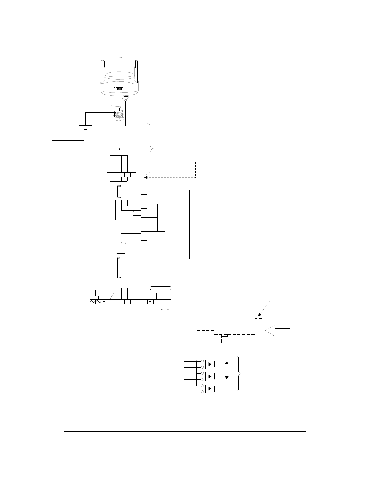
Connection diagram
9 7 5 4 6
Connection
box
2 meters of cable - part of WSS
4 x 0.75mm²
cable lenght
max. 300m 1
2
3
4
5
6
7
8
9
10
11
12
13
14
15
+
Power
18-32V
+ B ASD
Not used
InputSupply
DO NOT
connect Display
WSDI
WSS
WSS interface box
3
4
2
D = wind Direction
S = wind Speed
The WSS box has to be mounted indoor,
recommended is close to the indicator.
1 2 3 4 5 A B 9 10 11
220V AC
EARTH
+5V
0V
wind Speed
DIRECTION
SCREEN
SIGNAL
RETURN
SCREEN
MODE
Display
WSDI
9
10
11
1
LISTENER
ACCORDING TO
NMEA 0183
MODE
EXTERNAL
CONTROL
STANDARD
LISTENER
LISTENERS
MULTIPLE
E.g. VDR
Alternatively use the
IP67 Con
nect
or
kit option
IMPORTANT!
Connect to the
ship’
s earth cable
(or steel hull).

WSI, WSDI, WSS or WSS-L User’s Manual
DEIF A/S
Page 18 of 19
Connection diagram for 3 displays
+5V
0V
SPEED
DIRECTION
SCREEN
SCREEN
MODE
11
10
9
B
A
5
4
3
2
1
1
2
3
4
5
A
B
9
10
11
MODE
DIRECTION
SPEED
0V
+5V
+5V
0V
SPEED
DIRECTION
SIGNAL
RETURN
MODE
11
10
9
B
A
5
4
3
2
1
SUPPLY
COMMON OR
INDIVIDUAL
LISTENER
ACCORDING TO
NMEA 0183
EXTERNAL
CONTROL
SUPPLY
STANDARD
Display
CABLE
WSDI
SUPPLY
SCREEN
SCREEN
EARTH
SCREEN
EARTH
EARTH
SCREEN
TO WSS INTERFACE BOX
12
10
11
TO CABLE SCREEEN
RETURN
SIGNAL
RETURN
SIGNAL Display
WSDI
Display
WSDI

WSI, WSDI, WSS or WSS-L User’s Manual
DEIF A/S
Page 19 of 19
Interface box
DEIF A/S reserves the right to change any of the above.
85.0
75.0
110.0
61.0
4.5
99.7
15 14 13 12 11 10 9 8 7 6 5 4 3 2 1
This manual suits for next models
3
Table of contents
Other Deif Measuring Instrument manuals

Deif
Deif XDi Series User manual

Deif
Deif Insight User manual

Deif
Deif BRW-2 User manual

Deif
Deif TRI-2 User manual

Deif
Deif MIB 7000 User manual

Deif
Deif AGC 150 User manual

Deif
Deif BRW-2 User manual

Deif
Deif BRW-2 User manual

Deif
Deif MIC-2 MKII User manual

Deif
Deif MIC-2 MKII Operating and maintenance instructions


Popular Measuring Instrument manuals by other brands


Emerson
Emerson FloBoss 103 instruction manual

S+S Regeltechnik
S+S Regeltechnik RHEASREG KLSW Operating Instructions, Mounting & Installation

Envent
Envent 330S user manual

Stabila
Stabila LD 400 operating instructions

Hanna Instruments
Hanna Instruments Gro Line HI981030 instruction manual

Ankom
Ankom 2000 Operator's manual


